
User Manual
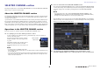
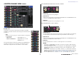
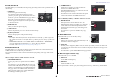
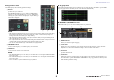
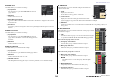
Table Of Contents
- How to Use This Reference Manual
- Contents
- Function Tree
- SELECTED CHANNEL section
- Centralogic section
- Input and output patching
- Input channels
- Signal flow for input channels
- Specifying the channel name, icon and channel color
- Making HA (Head Amp) settings
- Sending a signal from an input channel to the STEREO/MONO buses
- Sending a signal from an input channel to a MIX/ MATRIX bus
- Correcting delay between channels (Input Delay)
- Channel library operations
- Output channels
- EQ and Dynamics
- Grouping and linking
- Scene memory
- About scene memories
- Using scene memories
- Editing scene memories
- Using the Global Paste function
- Using the Focus function
- Using the Recall Safe function
- Using the Fade function
- Outputting a control signal to an external device in tandem with scene recall (GPI OUT)
- Playing back an audio file that links to a scene recall
- Using Preview mode
- Monitor and Cue functions
- Talkback and Oscillator
- Meters
- Graphic EQ, effects, and Premium Rack
- I/O device and external head amp
- MIDI
- User settings (Security)
- Recorder
- Help function
- Other functions
- About the SETUP screen
- Word clock and slot settings
- Using cascade connections
- Basic settings for MIX buses and MATRIX buses
- Switching the entire phantom power supply on/ off
- Specifying the brightness of the touch screen, LEDs, channel name displays, and lamps
- Setting the date and time of the internal clock
- Setting the network address
- Initializing the unit to factory default settings
- Adjusting the detection point of the touch screen (Calibration function)
- Adjusting the faders (Calibration function)
- Fine-tuning the input and output gain (Calibration function)
- Adjusting the channel color (Calibration function)
- Adjusting the brightness of the channel name display
- Adjusting the contrast of the channel name display
- Dante audio network settings
- Using GPI (General Purpose Interface)
- Appendices
- EQ Library List
- DYNAMICS Library List
- Dynamics Parameters
- Effect Type List
- Effects Parameters
- Premium Rack Processor Parameters
- Effects and tempo synchronization
- Parameters that can be assigned to control changes
- NRPN parameter assignments
- Mixing parameter operation applicability
- Functions that can be assigned to USER DEFINED keys
- Functions that can be assigned to USER DEFINED knobs
- Functions that can be assigned to the assignable encoders
- MIDI Data Format
- Warning/Error Messages
- Electrical characteristics
- Mixer Basic Parameters
- M IDI Implementation Chart
- Index

SELECTED CHANNEL section
Reference Manual
7
SELECTED CHANNEL VIEW screen
■ SEND field
In this field, you can view the send level from the channel to each MIX/
MATRIX bus, switch the on/off status of the send signals, and switch between
pre and post.
1 Tabs
Enable you to select a group of 16 output bus channels to be displayed
in the SEND field.
• MIX1–16 tab.............................. displays MIX buses 1–16.
• MIX17–24/MATRIX tab......... displays MIX buses 17–24 and
MATRIX buses 1–8.
The view and the function of the knobs and buttons in the SEND field vary
depending on whether a pair of bus channels (odd-numbered and even-
numbered) are comprised of two mono channels or a stereo channel.
If the destination bus channels are two mono channels:
1 SEND knob
Sets the send level to the corresponding bus.
2 PRE indicator
Indicates the send point of the corresponding bus. If the PRE button on the MIX SEND 8ch screen
is turned ON, this PRE indicator will be turned on.
3 ON button
Switches the send signal to the corresponding bus on or off.
If the destination bus is a stereo channel:
1 SEND/PAN knob
The right-hand knob adjusts the level of the signal sent to a pair of bus channels (even-numbered
and odd-numbered). The left-hand knob adjusts the pan and balance of the same signal.
2 PRE indicator
Indicates the send point of the corresponding bus. If the PRE button on the MIX SEND 8ch screen
is turned ON, this PRE indicator will be turned on.
3 ON button
Press the right-hand button to switch on or off the signal sent to two bus channels.
NOTE
• If the indices of a SEND/PAN knob are white, the send point is assigned as PRE; if the indices
are black, it is assigned as POST.
• If the send point is PRE, you can specify the PRE point as either VARI [PRE EQ] or VARI [PRE
FADER] in the BUS SETUP popup that appears when you press the SETUP button → BUS
SETUP button.
• If the type of the destination bus is set to FIXED, controllers
1–2 mentioned above will not be
displayed. The send level will be fixed at nominal level, and the send point will be fixed at POST
FADER. For details, see “Basic settings for MIX buses and MATRIX buses” on page 202.
• Press the SEND LEVEL knob or PAN knob on screen to open the SEND 8ch popup window.
1
1
2
3
1
2
3