
User Manual
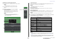
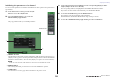

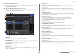

Table Of Contents
- How to Use This Reference Manual
- Contents
- Function Tree
- SELECTED CHANNEL section
- Centralogic section
- Input and output patching
- Input channels
- Signal flow for input channels
- Specifying the channel name, icon and channel color
- Making HA (Head Amp) settings
- Sending a signal from an input channel to the STEREO/MONO buses
- Sending a signal from an input channel to a MIX/ MATRIX bus
- Correcting delay between channels (Input Delay)
- Channel library operations
- Output channels
- EQ and Dynamics
- Grouping and linking
- Scene memory
- About scene memories
- Using scene memories
- Editing scene memories
- Using the Global Paste function
- Using the Focus function
- Using the Recall Safe function
- Using the Fade function
- Outputting a control signal to an external device in tandem with scene recall (GPI OUT)
- Playing back an audio file that links to a scene recall
- Using Preview mode
- Monitor and Cue functions
- Talkback and Oscillator
- Meters
- Graphic EQ, effects, and Premium Rack
- I/O device and external head amp
- MIDI
- User settings (Security)
- Recorder
- Help function
- Other functions
- About the SETUP screen
- Word clock and slot settings
- Using cascade connections
- Basic settings for MIX buses and MATRIX buses
- Switching the entire phantom power supply on/ off
- Specifying the brightness of the touch screen, LEDs, channel name displays, and lamps
- Setting the date and time of the internal clock
- Setting the network address
- Initializing the unit to factory default settings
- Adjusting the detection point of the touch screen (Calibration function)
- Adjusting the faders (Calibration function)
- Fine-tuning the input and output gain (Calibration function)
- Adjusting the channel color (Calibration function)
- Adjusting the brightness of the channel name display
- Adjusting the contrast of the channel name display
- Dante audio network settings
- Using GPI (General Purpose Interface)
- Appendices
- EQ Library List
- DYNAMICS Library List
- Dynamics Parameters
- Effect Type List
- Effects Parameters
- Premium Rack Processor Parameters
- Effects and tempo synchronization
- Parameters that can be assigned to control changes
- NRPN parameter assignments
- Mixing parameter operation applicability
- Functions that can be assigned to USER DEFINED keys
- Functions that can be assigned to USER DEFINED knobs
- Functions that can be assigned to the assignable encoders
- MIDI Data Format
- Warning/Error Messages
- Electrical characteristics
- Mixer Basic Parameters
- M IDI Implementation Chart
- Index

Scene memory
Reference Manual
77
Scene memory
This chapter explains how to perform scene memory operations.
About scene memories
On CL series consoles, you can assign a name to a set of mix parameter and input/output port patch
settings, and store the mix settings in memory (and later recall them from memory) as a “scene.”
Each scene is assigned a number in the range of 000–300. Scene 000 is a read-only scene used to
initialize the mix parameters. Scenes 001–300 are writable scenes.
Each scene contains the position of the top panel faders and [ON] key status, as well as the following
parameters.
• Input/output port patching
• Channel name and color
•Bus settings
• Head amp settings
• Digital gain settings
• EQ settings
• Dynamics 1 and 2 settings
• Input delay settings
• Rack (GEQ/effect/Premium Rack) settings
• Pan/balance settings
• Insert/Direct Out settings
• On/off status and send level of signals sent to MIX buses
• On/off status and send level of signals sent to MATRIX buses
• Settings for signals sent to the STEREO/MONO bus
• DCA group settings
• Mute group settings
• Channel link settings
• Panel assignment status (PANEL SNAPSHOT)
Using scene memories
Storing and recalling scenes
To store the current mix settings as a scene in memory and recall it later, you can use the keys in the
SCENE MEMORY/MONITOR section on the top panel, or you can use the SCENE LIST window.
■ Using the keys in the SCENE MEMORY/MONITOR section
1. Use the controllers on the top panel or the buttons on the touch screen to set the
mix parameters as desired.
2. Use the SCENE MEMORY [INC]/[DEC] keys to
select the store-destination scene number.
The number of the currently-selected scene appears in
the SCENE field in the Function Access Area. When
you select a new scene number, the number will blink.
This blinking indicates that the displayed scene
number is different from the currently-loaded scene
number.
This field always displays general information about the scene. You can press this field to access
the SCENE LIST window, in which you can view and edit additional settings for the scene.
1 Scene number
Indicates the number of the currently-selected scene.
2 R symbol (READ ONLY)/Protect symbol
Read-only scenes are indicated by an R symbol (READ ONLY) displayed here. Write-protected
scenes are indicated by a Protect symbol.
3 Scene title
Indicates the title of the currently-selected scene.
4 E symbol (EDIT symbol)
This symbol appears when you edit the mix parameters for the currently-loaded scene.
This symbol indicates that you must execute the Store operation if you want to keep the changes
you made.
4
3
2 21