
User Manual
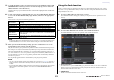
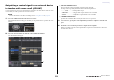
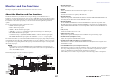
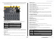
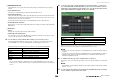
Table Of Contents
- How to Use This Reference Manual
- Contents
- Function Tree
- SELECTED CHANNEL section
- Centralogic section
- Input and output patching
- Input channels
- Signal flow for input channels
- Specifying the channel name, icon and channel color
- Making HA (Head Amp) settings
- Sending a signal from an input channel to the STEREO/MONO buses
- Sending a signal from an input channel to a MIX/ MATRIX bus
- Correcting delay between channels (Input Delay)
- Channel library operations
- Output channels
- EQ and Dynamics
- Grouping and linking
- Scene memory
- About scene memories
- Using scene memories
- Editing scene memories
- Using the Global Paste function
- Using the Focus function
- Using the Recall Safe function
- Using the Fade function
- Outputting a control signal to an external device in tandem with scene recall (GPI OUT)
- Playing back an audio file that links to a scene recall
- Using Preview mode
- Monitor and Cue functions
- Talkback and Oscillator
- Meters
- Graphic EQ, effects, and Premium Rack
- I/O device and external head amp
- MIDI
- User settings (Security)
- Recorder
- Help function
- Other functions
- About the SETUP screen
- Word clock and slot settings
- Using cascade connections
- Basic settings for MIX buses and MATRIX buses
- Switching the entire phantom power supply on/ off
- Specifying the brightness of the touch screen, LEDs, channel name displays, and lamps
- Setting the date and time of the internal clock
- Setting the network address
- Initializing the unit to factory default settings
- Adjusting the detection point of the touch screen (Calibration function)
- Adjusting the faders (Calibration function)
- Fine-tuning the input and output gain (Calibration function)
- Adjusting the channel color (Calibration function)
- Adjusting the brightness of the channel name display
- Adjusting the contrast of the channel name display
- Dante audio network settings
- Using GPI (General Purpose Interface)
- Appendices
- EQ Library List
- DYNAMICS Library List
- Dynamics Parameters
- Effect Type List
- Effects Parameters
- Premium Rack Processor Parameters
- Effects and tempo synchronization
- Parameters that can be assigned to control changes
- NRPN parameter assignments
- Mixing parameter operation applicability
- Functions that can be assigned to USER DEFINED keys
- Functions that can be assigned to USER DEFINED knobs
- Functions that can be assigned to the assignable encoders
- MIDI Data Format
- Warning/Error Messages
- Electrical characteristics
- Mixer Basic Parameters
- M IDI Implementation Chart
- Index

Monitor and Cue functions
Reference Manual
97
Monitor and Cue functions
This chapter explains the Monitor and Cue functions of CL series consoles.
About the Monitor and Cue functions
The Monitor function lets you audition various outputs through your nearfield monitors or
headphones. On the front panel of the CL series console is a PHONES Out jack for monitoring, which
enables you to monitor the monitoring source signal at any time. By assigning the MONITOR OUT L/
R/C channels to the desired output jacks, you can also monitor the same signal through external
speakers.
You can select the following signals as the monitor source.
• STEREO channel output signal
• MONO channel output signal
• STEREO + MONO channel output signal
• OMNI IN 1–2, 3–4, 5–6, 7–8 channel input signal (for monitoring a two channnel pair)
• RECORDER PLAYBACK output signal
• A combination of up to eight MIX, MATRIX, STEREO, or MONO channel output signals,
RECORDER PLAYBACK output signals, and OMNI IN 1–2, 3–4, 5–6, 7–8 input signals
The Cue function enables you to check an individual channel or DCA group by temporarily monitoring
it via MONITOR OUT, CUE OUT, or PHONES. When you press the [CUE] key on the top panel, the
cue signal of the corresponding channel or DCA group is sent as the monitor output or cue output from
the selected output port.
NOTE
Be aware that if you turn CUE INTERRUPTION off in the MONITOR popup window, the cue
signal will not be sent to the connected monitor speakers. However, the cue signal will always be
sent to the PHONES Out jack.
The following diagram shows the cue/monitor signal flow.
• MONITOR SELECT
Selects the monitor source.
• METER
Detects and indicates the level of the monitor signal or cue signal.
• DIMMER
Attenuates the monitor/cue signal by a fixed amount.
• MONITOR LEVEL
Adjusts the output level of the MONITOR OUT L/R/C channels. If PHONES LEVEL LINK is ON,
this setting will also affect the level at the PHONES Out jack.
• MONITOR FADER
Use the STEREO MASTER fader or MONO MASTER fader to adjust the output level of the
MONITOR OUT L/R/C channels. MONITOR FADER is positioned in series with MONITOR
LEVEL. If PHONES LEVEL LINK is ON, this setting will also affect the level at the PHONES Out
jack.
• ON (on/off)
Switches the Monitor function on or off.
• DELAY (Monitor delay)
Delays monitor signals. The Delay function is disabled if cue signals are being output.
• PHONES LEVEL (Headphone level)
Adjusts the output level at the PHONES Out jack.
• PHONES LEVEL LINK (Headphone Level Link function)
If this function is turned on, the MONITOR LEVEL knob will adjust the level of signals sent to
the PHONES Out jack.
• CUE INTERRUPTION (Cue Interruption function)
If this function is turned on, pressing the [CUE] key on the top panel will cause the cue signal of
the corresponding channel or DCA group to be sent as the monitor output from the selected
output port. With the factory default settings, this function is turned on.
Turn it off if you do not want to output cue signals to the monitoring speakers or headphones.
MONITOR L
MONITOR R
MONITOR MONO(C)
MONITOR OUT MONO(C)
MONITOR OUT R
MONITOR OUT L
To OUTPUT PAT CH
To OUTPUT PAT CH
To OUTPUT P AT CH
MONO
METER
MONITOR R
METER
MONITOR MONO(C)
TAL KBAC K ON
METER
MONITOR L
CUE TRIM
(INPUT/OUTPUT/DCA)
CUE L
CUE R
MONO
METER
CUE L
METER
CUE R
ON
MONITOR
LEVEL
DIMMER
MONITOR DIMM ON
CUE LOGIC
+MONO(C)
MONITOR SELECT
MATRIX OUT1-8
MIX OUT1-24
OMNI IN 1/2
DEFINE
MIX
(MAX:8ch)
OMNI IN 3/4
OMNI IN 5/6
OMNI IN 7/8
STEREO OUT L,R
STEREO OUT MONO(C)
STEREO OUT L,C,R
PHONES L
PHONES R
To PHONES OUT
To PHON E S O U T
DELAY
(MAX:1000ms)
DELAY
(MAX:1000ms)
PHONES
LEVEL LINK
An output port delay becomes invalid by
assigning a monitor out to the output port.
CUE OUT L
CUE OUT R
To OUTPUT P AT CH
To OUTPUT PATCH
CUE OUT ON
PLAYBACK OUT
OMNI IN 1/2
OMNI IN 3/4
OMNI IN 5/6
OMNI IN 7/8
PLAYBACK OUT
STEREO OUT L,R
STEREO OUT MONO(C)
CUE L BUS
CUE R BUS
DELAY
(MAX:1000ms)
DELAY
(MAX:1000ms)
DELAY
(MAX:1000ms)
MONITOR
FADER
CUE INTERRUPTION
CUE ON
DELAY
(MAX:1000ms)
DELAY
(MAX:1000ms)
ON
MONITOR DELAY AUTO BYPASS
CUE OUT
LEVEL