Electronic Acoustic Drum Module Owner’s Manual Quick Guide page 6 Features of the EAD10 page 10 EN
For EAD10 SPECIAL MESSAGE SECTION This product utilizes batteries or an external power supply (adapter). DO NOT connect this product to any power supply or adapter other than one described in the manual, on the name plate, or specifically recommended by Yamaha. WARNING: Do not place this product in a position where anyone could walk on, trip over, or roll anything over power or connecting cords of any kind.
For AC adaptor and EAD10 FCC INFORMATION (U.S.A.) 1. IMPORTANT NOTICE: DO NOT MODIFY THIS UNIT! This product, when installed as indicated in the instructions contained in this manual, meets FCC requirements. Modifications not expressly approved by Yamaha may void your authority, granted by the FCC, to use the product. 2. IMPORTANT: When connecting this product to accessories and/ or another product use only high quality shielded cables. Cable/s supplied with this product MUST be used.
For AC adaptor This device complies with Part 15 of the FCC Rules. Operation is subject to the following two conditions: (1) this device may not cause harmful interference, and (2) this device must accept any interference received, including interference that may cause undesired operation.
OBSERVERA! Apparaten kopplas inte ur växelströmskällan (nätet) så länge som den ar ansluten till vägguttaget, även om själva apparaten har stängts av. ADVARSEL: Netspændingen til dette apparat er IKKE afbrudt, sålænge netledningen sidder i en stikkontakt, som er tændt — også selvom der er slukket på apparatets afbryder. VAROITUS: Laitteen toisiopiiriin kytketty käyttökytkin ei irroita koko laitetta verkosta.
PRECAUTIONS PLEASE READ CAREFULLY BEFORE PROCEEDING Please keep this manual in a safe and handy place for future reference. For AC adaptor WARNING CAUTION • This AC adaptor is designed for use with only Yamaha electronic instruments. Do not use for any other purpose. • Indoor use only. Do not use in any wet environments. • When setting up, make sure that the AC outlet is easily accessible.
CAUTION Always follow the basic precautions listed below to avoid the possibility of physical injury to you or others, or damage to the instrument or other property. These precautions include, but are not limited to, the following: Power supply/AC adaptor Connections • Do not connect the instrument to an electrical outlet using a multiple-connector. Doing so can result in lower sound quality, or possibly cause overheating in the outlet.
NOTICE Information To avoid the possibility of malfunction/ damage to the product, damage to data, or damage to other property, follow the notices below. About copyrights Handling • Do not use the instrument in the vicinity of a TV, radio, stereo equipment, mobile phone, or other electric devices. Otherwise, the instrument, TV, or radio may generate noise.
The model number, serial number, power requirements, etc., may be found on or near the name plate, which is at the bottom of the unit. You should note this serial number in the space provided below and retain this manual as a permanent record of your purchase to aid identification in the event of theft. Model No. Serial No.
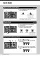
Quick Guide Adjusting Volume and Sound Balance 1. 1 (page 13) Turn the [MASTER VOLUME] knob or [AUDIO/ CLICK VOLUME] knob. Overall volume Volume control for the AUX IN (auxiliary input) and Metronome (click)—sounds other than what you play Hit all drums and cymbals in the drum set to make sure that the EAD10 is picking up the sound. Changing Sounds (page 33) 1 1. Turn the [SCENE] knob to select different sounds (Scenes). 2. Adjust the levels with the [REVERB], [EFFECT], and [TRIGGER] knobs.
Quick Guide Playing Along with a Favorite Song 2 1 (page 24) 1. Connect a portable music player to the [AUX IN] jack. 2. Start music playback on your portable player. 3. Play the drums while listening with headphones. 3 Recording Your Performance 2, 4 3 1 (page 41) 1. 2. Press the [RECORDER] button. 3. 4. Play the drums. Press the button below “” to start recording. Press the button below “ ing.
Contents PRECAUTIONS Quick Guide Included Accessories Features of the EAD10 2 6 9 10 How the EAD10 makes sound........................................... 11 About the Manuals 12 Printed Manual .................................................................. 12 Digital Manual (PDF) ......................................................... 12 Panel Controls and Functions 13 Main Unit ........................................................................... 13 Sensor Unit......................
Welcome Thank you for purchasing this Yamaha product. To get the most out of your EAD10, be sure to read this Owner’s Manual carefully. And after reading through this manual, be sure to store it in a safe place so that you can refer back to it again as needed.
Features of the EAD10 Main Unit Sensor Unit The EAD10 lets you easily change the sound of your acoustic drums into the sound of your liking. Connect a smart phone to the EAD10 and enjoy playing the drums along with your favorite music. Also, it can be used in a wide range of applications from practice, recording to live situations.
How the EAD10 makes sound Sensor Unit Audio signal from the drum set Trigger signal from the bass drum (Mic sound &) Effects Trigger Sound (internal Voices) Trigger sensor Mic sensor Main Unit Reverb The Sensor Unit sends two types of signals to the Main Unit; an audio signal captured with the mic sensor, and a trigger signal captured with the trigger sensor.
About the Manuals The following manuals are provided for using the EAD10. These manuals are intended for users of the EAD10. Printed Manual Owner’s Manual (this book) Setup Guide Explains how to attach and setup the EAD10 for producing sound. Basic Guide Describes the fundamentals needed to operate the EAD10. Application Guide Describes parameter settings and other more advanced uses. Reference Describes troubleshooting techniques and contains other reference materials.
Panel Controls and Functions Main Unit Top Panel [SCENE] knob (page 33) Switches between the different sound sets. Or, returns to the Scene screen from other screens. [ ] (Standby/On) switch (page 25) Switches the power between standby (off) and on. NOTE The knob can be used in the same manner as the [–] and [+] buttons. For more information, refer to the Reference Manual (Advanced) (PDF) (MENU/Utility/ General). [MASTER VOLUME] knob Adjusts the overall volume.
Panel Controls and Functions Rear Panel Sensor Unit [FOOT SW] Jack (page 48) Connects a foot pedal or foot switch (sold separately). FC5 FC7 HH65 etc. TO SENSOR UNIT [A] jack (page 17) Connect to the [A] jack on the Sensor Unit using the connector cable (included). TO SENSOR UNIT [B] jack Connect to the [B] jack on the Sensor Unit. For more information on the [qKICK/w] to [y] jacks, see “About the Trigger Input Jacks” (page 16). Standard phone plug (6.
Panel Controls and Functions Front Panel Standard stereo phone plug (6.3 mm) [PHONES] jack Connects headphones. This output jack is a standard stereo phone plug (6.3 mm). Use a 3.5 mm stereo mini to (6.3 mm) stereo adaptor to connect headphones or earphones with a stereo mini plug (3.5 mm) to the [PHONES] jack. CAUTION Do not use headphones for a long period of time at high volume. Doing so can cause loss of hearing. Sensor Unit NOTICE Do not hit the Sensor Unit with the drumsticks.
Panel Controls and Functions About the Trigger Input Jacks Trigger signals are received via the trigger input jacks. These are used for connecting separately sold accessories to the EAD10. You can connect up to six pads or drum triggers. [qKICK/w] through [y] jacks are located on the rear panel of the Main Unit. Trigger Input jacks [qKICK/w] [eSNARE/r] [t] and [y] The TO SENSOR UNIT [A] jack can be as the [qKICK/w] jack (page 48). This jack consists of a pair of mono trigger inputs.
Setup Guide This provides information on setup and initial settings in preparation for playing. Workflow Attaching the Sensor Unit Installing the Main Unit Connecting the Cables Taking Measures Against Noise Connecting the AC adaptor Setting Up the Sensor Unit This completes set up. Setting Up Positioning the drum set The bass drum should be the central point in the drum set, with the snare, toms, cymbals, positioned in a well balanced manner around it.
Setup Guide Setting Up Attaching the Sensor Unit Attach the Sensor Unit to the top of the batter side bass drum hoop. Standard Straight Hoop Wood hoops 1. Slide the Sensor Unit onto the top of the batter side bass drum hoop as far as possible. 2. Lift the Sensor Unit and after making sure both surfaces shown in the figure below are in contact with the hoop, turn the clamp screw. Tighten the clamp screw firmly, making sure that the Sensor Unit is secure and not loose.
Setup Guide Setting Up Installing the Main Unit Either place the Main Unit on a table, or attach the Main Unit to a hi-hat stand. Placing on a Flat Surface Place the Main Unit on a table or flat surface. Mounting on a Hi-Hat Stand 1. Combine the included module holder with a separately sold cymbal stand attachment (CSAT924A) and mount on the hi-hat stand. Tighten the module holder wing nuts to securely fasten the Main Unit and module holder.
Setup Guide Setting Up About the Module Holder The module holder has three sets of holes. Use the center set of holes to mount in a standard position. Use the rear set of holes if you want the unit positioned forward, and use the front set of holes to position the unit to the rear. NOTE The module holder is 22.2 mm (7/8") diameter. Main Unit Front panel side Rear position Standard position Forward position Main Unit Rear panel side Angle adjustment key bolt Module holder Module holder 2.
Setup Guide Setting Up Taking Measures Against Noise To eliminate the cause of the noise, adjust positions beforehand so that your toms do not touch the Sensor Unit or that the Connector Cables do not move around the Sensor Unit during your performance. Check the Sensor Unit Location Example of poor placement Make sure the Sensor Unit does not touch the toms or other instruments. Securing the Cables Position the L-shaped plugs connected the Sensor Unit on their sides.
Setup Guide Setting Up Connecting the AC adaptor WARNING Only use the specified AC adaptor (page 63). Using a different AC adaptor can cause malfunction, overheating, fire, and other problems. This may void the warranty so please take careful note. CAUTION Locate the Main Unit close to an AC outlet. If you notice any abnormalities during operation, turn the power off immediately and unplug the AC adaptor. 1. Make sure that the power is turned off (all panel lights and the screen backlight are off).
Setup Guide Setting Up 4. Hook the AC adaptor’s cord around the cord hook to secure it in place. CAUTION Excessive bending can damage the AC adaptor cord and create a fire hazard. Ensure, therefore, that the power cord is not bent at an extreme angle when wrapped around the hook. Cord hook AC adaptor cord 5. Plug the AC adaptor’s AC plug into a domestic power outlet.
Setup Guide Connect with Other Devices and Expand the Fun Connect with Other Devices and Expand the Fun This section describes how to connect to a portable music player and PA system. Connecting a Portable Music Player You can play along with audio playback from a smartphone or portable music player. NOTICE Before making any connections, make sure volume levels on all devices are set at their minimum. Connect the smartphone or portable music player to the [AUX IN] jack. Stereo mini plug (3.
Setup Guide Turning On or Off Connecting a Computer If you have a computer and DAW software, connect the Main Unit to the computer and you can record your performance and listen to the playback from the computer. For more information, refer to the Reference Manual (Advanced) (PDF). Precautions when using the [USB TO HOST] terminal When connecting the computer to the [USB TO HOST] terminal, make sure to observe the following points.
Setup Guide Turning On or Off 3. If you are connected to a PA system: Turn the external speakers on. Power on Turning Off NOTICE • The Main Unit automatically stores settings when the power is turned off, so do not unplug the AC adaptor until the LCD screen is turned off completely. • Unsaved Scene data will lost, so always save (Store) data before turning the power off. 1. If you are connected to a PA system: Turn the external speakers off. Power off 2.
Setup Guide Setting Up the Sensor Unit Setting Up the Sensor Unit About the Sensor Unit Settings Adjust the gain and sensitivity settings for the Mic sensor and Trigger sensor built into the Sensor Unit. When you need to adjust the gain, you can also use the Auto Setting feature. Setting Screen display Optimal condition MIC (Mic gain) The level should occasionally reach to the right and the [ ] (Sensor Unit) button lights by striking all the instruments in the drum set.
Setup Guide Setting Up the Sensor Unit Manually Adjusting the Sensor Unit Settings 1. Press the [ ] (Sensor Unit) button. The SENSOR UNIT screen appears. Press the [EXIT] button to return to the Scene screen. Mic gain Trigger gain 2. Use the buttons below “ ” or “ ” ([F1] or [F2]) to move the cursor. 3. Use the [–] or [+] buttons to adjust the value. Lower Higher Setting Finer Adjustments 1. With the SENSOR UNIT screen displayed, press the button below “ SENSOR UNIT screen ” ([F2]).
Setup Guide Changing the Overall Settings 2. Use the buttons below “ ” or “ ” ([F1] or [F2]) to move the cursor. 3. Use the [–] or [+] buttons to adjust the value. Lower Higher Changing the Overall Settings Auto Power-Off The Auto Power-Off function automatically turns off the Main Unit after a certain period of inactivity. The factory default is set at 30 minutes. NOTICE • Unsaved data is lost when the Main Unit is turned off with the Auto Power-Off function.
Setup Guide Using a USB Flash Drive Restoring Main Unit Settings to the Factory Defaults (Factory Reset) Use the Factory Reset function to restore the Main Unit’s settings to their factory defaults, even if you have accidentally overwritten them. NOTICE A factory reset overwrites any settings you have made with the corresponding factory defaults. Save any important userdefined data to a USB flash drive before carrying out a factory reset.
Setup Guide Using a USB Flash Drive Compatible USB Devices USB flash drives only Please check the URL shown below for a list of compatible USB flash drives. http://download.yamaha.com/ NOTE • Other USB devices such as USB hub, mouse, computer keyboard, cannot be used. • A USB cable cannot be used to connect a USB device to the [USB TO DEVICE] terminal. NOTICE The rating of the [USB TO DEVICE] terminal is a maximum of 5 V / 500 mA.
Basic Guide Performing with Various of Scenes What is a Scene? A Scene consists of a group of assigned settings for Reverb, Effects, and Trigger Sounds. The Main Unit includes preset Scenes you can select to change the overall sound. Scene Reverb Studio Stage Concert Hall Simulates the acoustical characteristics of a venue or studio. For example, you can recreate the ambiance of a live venue in the comfort of your own home.
Basic Guide Performing with Various of Scenes Basic Scene Operation NOTE Switches the Scene type. Returns you to the Scene Screen from other screens. When in the screens listed below, the knob can be used like the [–] and [+] buttons without returning to the Scene Screen.
Basic Guide Performing with Various of Scenes Selecting a Scene 1. Rotate the [SCENE] knob. Scene number Scene name Scene number and Scene name are displayed on the screen. P***: Preset Scene (Presets that are already stored in the EAD10) U***: User Scene (Scene you have created) NOTE When you select another Scene before storing the Scene being edited, you can use the recall function to recall the edited contents.
Basic Guide Creating Your Own Scene Creating Your Own Scene You can customize preset Scenes to create your own Scene. NOTE To check the Trigger Sound, turn the [TRIGGER] knob clockwise to increase the volume. Changing the Reverb Type 1. Press the button below “REV” ([F1]). The REVERB TYPE screen opens. Changing the Effect Type 1. Press the button below “EFF” ([F2]). The EFFECT TYPE screen opens. Changing the Trigger Sound Changing the Trigger Sound on the Bass Drum (Set as a Factory Default) 1.
Basic Guide Creating Your Own Scene Advanced Trigger Sound Settings When you attach a Drum Trigger on the snare drum, or add a DTX series pad, you need to assign a Trigger Sound to each device to play Trigger Sounds. This section describes how to change instrument categories to assign different Trigger Sounds, how to audition Trigger Sounds, and how to turn off the Trigger Sound by switching the “BYPASS” setting. 1. Press the button Switching the Pad below “TRG” ([F3]).
Basic Guide Creating Your Own Scene Using Imported Sounds (.wav) You can import audio files (.wav) into the EAD10 to use as Trigger Sounds. For more information on importing audio files and settings, refer to the Reference Manual (Advanced) (PDF). (MENU/Job/ Wave) For more information on using a USB flash drive, see “Using a USB Flash Drive” (page 30). Saving a Scene Under a New Name 1. Press the [STORE] button. The STORE screen opens.
Basic Guide Creating Your Own Scene 4. After entering all characters, press the button below “OK” ([F2]) and return to the STORE screen. 5. Use the [–] or [+] buttons to select a User Scene Number to store your Scene to. NOTE You can also use the [SCENE] knob to make changes. 6. After confirming the new Scene Number and Scene Name, press the button below “STORE” ([F3]). NOTE You cannot save an edited Scene to a Preset Scene.
Basic Guide Using the Click (Metronome) Using the Click (Metronome) Set the Click (Metronome) tempo, volume, type of sound, etc. 1. Press the [ ] (Click) button. Changing the Tempo Slower The CLICK screen opens. Press the [EXIT] button to return to the previous screen or the Scene screen. Faster Setting the Tempo by Tapping the Button (Tap Tempo) Starting and Stopping the Click 2. Press the button below “ ” ([F1]) to start the Click.
Basic Guide Using the Click (Metronome) (continued from the previous page) VOLUME/BEAT screen Set the volume Accents Quarter notes Eighth notes Sixteenth notes Set the time signature Eighth note Beats triplets (1/4−16/4, 1/8−16/8, 1/16−16/16) 3/8, 6/8, 9/8, 12/8, 15/8 beats only have settings for Acc, dotted quarter, eighth, and sixteenth notes. Setting Individual Click Beat Volumes Changing the Click Sounds 3. 3. Use the buttons below “<” or ”>” ([F1] or [F2]) to move the cursor. 4.
Basic Guide Recording Your Performance Recording Your Performance Use the EAD10 to record your performance. When a USB flash drive is connected to the unit, audio is recorded to the USB flash drive. Recording to the Main Unit (when no USB flash drive is connected to the terminal) 1. Press the [RECORDER] button. The [RECORDER] button lights while recording or during playback. The RECORDER screen opens. Press the [EXIT] button to return to the Scene screen.
Basic Guide Recording Your Performance Recording to a USB Flash Drive 1. Connect a USB flash drive to the [USB TO DEVICE] terminal on the rear panel. When a USB flash drive is connected • You can record up to 30 minutes at a time. • A new file is created every time you record. • Simultaneously press Playback and Record to overdub your performance onto the currently playing song. 2. Press the [RECORDER] button. Press the [EXIT] button to return to the Scene screen. The RECORDER (USB) screen opens.
Basic Guide Recording Your Performance Switching to AUX IN Recording The Input Source must be changed to record from the [AUX IN] jack. 1. Press the [RECORDER] button. 2. Press the button below “SOURCE” ([F3]). When recording to the Main Unit When recording to a USB flash drive A confirmation message appears. 3. Press the button below “YES” ([F1]). The setting is changed to the AUX IN recording. NOTE Your performance does not sound and is not recorded while in AUX IN recording.
Basic Guide Recording Your Performance Overdub Recording Your Performance onto an Accompaniment Song You can overdub your performance onto a accompaniment song that you’ve imported onto a USB flash drive and save your performance combined with the accompaniment song as a single audio file. NOTE If you play along to a track coming into the Aux Input, only your performance will be recorded. Preparing an Accompaniment Song (Audio File) • Importing from a Computer Save the audio file (.
Basic Guide Recording Your Performance 3. Press the button below “SOURCE” ([F3]). The “Switch to AUX IN recording?” confirmation screen appears. 4. Press the button below “YES” ([F1]), to switch to AUX IN Recording. 5. Press the button below “” ([F1]) on the EAD10 to start recording, and simultaneously press Playback on the portable music player to start playback of the accompaniment song. 6. After the song playback finishes, press the button below “ ” ([F1]) to stop recording.
Basic Guide Recording Your Performance Recording Yourself Playing Along with the Accompaniment Song 1. Use the [–] or [+] buttons to select the accompaniment you have prepared. 2. Press the button below “” ([F1]) and the button below “>” ([F2]) to start recording and playback. 3. Play the drums. 4. After you finish playing, press the button below “ ” ([F1]) to stop recording. NOTE Pressing the button below “” ([F2]) stops accompaniment playback, but recording continues.
Basic Guide Recording Your Performance Recording with Smart Device Apps NOTE To eliminate the risk of interference due to noise by your iPhone or iPad when used in combination with the EAD10, turn on the Airplane Mode and then turn on Wi-Fi. NOTICE Be sure to place your iPhone or iPad on a stable surface to prevent it from falling over and being damaged. Using apps compatible with the EAD10 provides greater convenience and a more enjoyable user experience.
Application Guide Enhance Your Drum Set with Separately Sold Add-Ons You can connect add-ons (sold separately) to the Main Unit’s Trigger Input jacks or Footswitch jack and play Trigger Sounds or switch functions. Here are some of the things you can do with separately sold add-ons.
Application Guide Enhance Your Drum Set with Separately Sold Add-Ons Connecting to the [FOOT SW] Jack Separately sold add-ons Pedal Main applications Switch functions Play Trigger Sounds Choose the pedal that best fits your needs.
Application Guide Enhance Your Drum Set with Separately Sold Add-Ons Using Drum Triggers to Play Trigger Sounds with Your Acoustic Drums (with Drum Triggers) Attach a Drum Trigger (sold separately) to the snare drum or tom, and connect the Drum Trigger to the Main Unit, you can play Trigger Sounds according to the timing and intensity of each stroke. For example, layer internal drum sounds to enhance the sound, or layer other instrument sounds like percussion or sound effects.
Application Guide Enhance Your Drum Set with Separately Sold Add-Ons 3. Connect the DT50S to the [eSNARE/r] jack on the Main Unit rear panel. Main Unit DT50S 4. Press the [MENU] button to make necessary settings for using DT50S. When the DT50S is connected to the [eSNARE/r] jack, settings can be used as they are, without having to make any changes. When any other drum trigger is connected, perform the following settings.
Application Guide Enhance Your Drum Set with Separately Sold Add-Ons Using Electronic Drum Pads to Play Sounds or Control Functions (with Add-on Pads) You can play drum, percussion or other sounds, or control functions using pads (sold separately) connected to the Main Unit. Pad Connection Example Pad Main Unit Procedure: Example) Connecting a TP70S 1. Turn off the Main Unit. Make sure the Main Unit is turned off before connecting. All off 2. Attach the pad.
Application Guide Enhance Your Drum Set with Separately Sold Add-Ons 3. Connect the TP70S to the [t] or [y] jack on the Main Unit rear panel. Main Unit 4. Turn on the Main Unit. 5. Press the [MENU] button to make necessary settings for using TP70S. When the TP70S is connected to the [t] jack or [y] jack, settings can be used as they are, without having to make any changes. When any other pad is connected, perform the following settings.
Application Guide Enhance Your Drum Set with Separately Sold Add-Ons Using a Pedal to Play Sounds or Control Functions (with a Foot Pedal or a Foot Controller) You can connect a foot pedal to the [FOOT SW] jack for a variety of uses. Procedure: Example) Connecting an HH65 1. Turn off the Main Unit. Make sure the Main Unit is turned off before connecting. All off 2. Connect the pedal’s plug to the [FOOT SW] HH65 jack on the Main Unit rear panel.
Reference Menu List MENU Scene Edit Inst Category . . . . . . . . . . . . . . . . . . . . . Instrument Category InstNumber . . . . . . . . . . . . . . . . . . . Instrument Number InstTune . . . . . . . . . . . . . . . . . . . . . . Instrument Tuning InstDecay . . . . . . . . . . . . . . . . . . . . . Instrument Decay InstPan . . . . . . . . . . . . . . . . . . . . . . . Instrument Pan Voice Category . . . . . . . . . . . . . . . . . . . . . Voice Category VoiceNumber . . . . . . . . . . . . . . . . . .
Reference Menu List MENU Trigger Input Mode Trg1/Trg2 . . . . . . . . . . . . . . . Trigger 1/Trigger 2 Input Mode Trg3/Trg4 . . . . . . . . . . . . . . . Trigger 3/Trigger 4 Input Mode Curve Velocity Curve . . . . . . . . . . . Velocity Curve Pad Type PadType . . . . . . . . . . . . . . . Select Pad Type Gain . . . . . . . . . . . . . . . . Gain Sensitivity . . . . . . . . . . . Sensitivity RejectTime . . . . . . . . . . Reject Time MinLevel . . . . . . . . . . . . Minimum Level MaxLevel . . . . . . . .
Reference Menu List MENU Job Scene Recall . . . . . . . . . . . . . . . Recall Sort . . . . . . . . . . . . . . . . Sort Exchange . . . . . . . . . . . . Exchange Clear . . . . . . . . . . . . . . . Clear Wave Import . . . . . . . . . . . . . . . Import Selected Audio File Import All . . . . . . . . . . . . Import All Audio Files Delete . . . . . . . . . . . . . . Delete Selected Audio File Delete All . . . . . . . . . . . . Delete All Audio Files Optimize . . . . . . . . . . . . .
Reference Troubleshooting Troubleshooting Symptom No sound Possible cause Solution Reference page EAD10 is not turned on Make sure that the power is turned on. page 25 The volume is not turned up Check the [MASTER VOLUME] knob setting. page 13 The cable is not properly connected or The cable is damaged Make sure that the Sensor Unit and Main Unit are properly connected with a stereo phone cable. page 17 Make sure the cable you are using is in good condition.
Reference Troubleshooting Symptom Hard to notice changes to settings Possible cause Solution Reference page Reverb/Effect level or Trigger Sound volume is too low Turn the [REVERB] knob, [EFFECT] knob, or [TRIGGER] knob to the right to adjust depth or volume. page 33 The Mic Gain is set too low Try using the automatic setting to set up the Sensor Unit. page 27 The volume for the headphones you are using is low Use highly-efficient headphones, closed-ear headphones, or earphones.
Reference Troubleshooting Symptom Sound is distorted Cannot record the Main Unit Cannot record to a USB flash drive Possible cause Solution Reference page Mic gain level is set too high Press the [ ] button and adjust the mic sensor settings. page 27 The Master Volume is set too high Turn the [MASTER VOLUME] knob to the left. page 13 An Effect is applied Adjust the distortion or other Effect setting.
Reference Message List Message List Message Description Are you sure? Confirms whether or not you want to execute the specified operation. Auto power off disabled. Appears when the [STORE] button is held down while turning on the power informing the user that the Auto Power Off function is disabled. Backup error. Appears when writing data to the Flash ROM has failed. If data was not be properly saved when turning off the unit, this message appears the next time the power is turned on.
Reference Message List Message Please stop recorder. Appears when performing an operation that exits the Recorder during recorder playback or recording. Stop the Recorder and try again. Recording time limit exceeded. Recording time is about 1 minute 30 seconds with internal memory, and about 30 minutes with a USB flash drive. Read only file. Appears when a read-only file is selected during a file operation. Sample is too long. Sample is too long and cannot be loaded. Sample is too short.
Reference Specifications Specifications Main Unit Tone Generator Block Recorder Audio Files Click-track Functions Control Interface Scenes Reverb Effects Trigger Sounds Tone generator Maximum polyphony Voices Internal memory USB flash drive Record/playback Recording time Format Import limit Playback sample rate Wave memory Maximum loadable sample size Sample format Tempo Time signatures Subdivisions Display Other Controllers Knobs Buttons Connectivity DC IN Headphones AUX IN OUTPUT USB Sensor i
Reference Index Index Symbols F R [ ] (Click) button .......................... 13 [ ] (Sensor Unit) button ......... 13, 27 [ ] (Standby/On) switch ......... 13, 25 [–] button, [+] button....................... 13 [F1], [F2], [F3] ............................... 13 Factory Reset................................ 30 Foot Controller .............................. 54 Foot Pedal..................................... 54 [FOOT SW] Jack ........................... 14 Front Panel.................................
Drums Limited Warranty LIMITED WARRANTY ON YAMAHA DRUMS, HARDWARE AND ACCESSORY PRODUCTS Thank you for selecting a YAMAHA product. YAMAHA products are designed and manufactured to provide a high level of defect-free performance. Yamaha Corporation of America (“YAMAHA”) is proud of the experience and craftsmanship that goes into each and every YAMAHA product.
66 EAD10 Owner’s Manual
For details of products, please contact your nearest Yamaha representative or the authorized distributor listed below. Pour plus de détails sur les produits, veuillez-vous adresser à Yamaha ou au distributeur le plus proche de vous figurant dans la liste suivante. NORTH AMERICA CANADA Yamaha Canada Music Ltd. 135 Milner Avenue, Toronto, Ontario M1S 3R1, Canada Tel: +1-416-298-1311 U.S.A. Yamaha Corporation of America 6600 Orangethorpe Avenue, Buena Park, CA 90620, U.S.A.
Manual Development Group © 2017 Yamaha Corporation Published 06/2017 POHD*.