XV16AL/XV16ALC XV16ATL/XV16ATLC SERVICE MANUAL LIT-11616-12-56 4WM-28197-E0
EAS00001 XV16AL/XV16ALC XV16ATL/XV16ATLC SERVICE MANUAL 1998 by Yamaha Motor Corporation, U.S.A. First Edition, October 1998 All rights reserved. Any reproduction or unauthorized use without the written permission of Yamaha Motor Corporation, U.S.A. is expressly prohibited. Printed in U.S.A.
EAS00003 NOTICE This manual was produced by the Yamaha Motor Company, Ltd. primarily for use by Yamaha dealers and their qualified mechanics. It is not possible to include all the knowledge of a mechanic in one manual. Therefore, anyone who uses this book to perform maintenance and repairs on Yamaha vehicles should have a basic understanding of mechanics and the techniques to repair these types of vehicles.
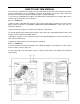
EAS00007 HOW TO USE THIS MANUAL This manual is intended as a handy, easy-to-read reference book for the mechanic. Comprehensive explanations of all installation, removal, disassembly, assembly, repair and check procedures are laid out with the individual steps in sequential order. 1 The manual is divided into chapters. An abbreviation and symbol in the upper right corner of each page indicate the current chapter. Refer to “SYMBOLS”. 2 Each chapter is divided into sections.
******** 1 2 GEN INFO SYMBOLS The following symbols are not relevant to every vehicle. Symbols 1 to 8 indicate the subject of each chapter. SPEC 3 4 CHK ADJ 1 General information 2 Specifications 3 Periodic checks and adjustments 4 Chassis 5 Engine 6 Carburetor 7 Electrical system 8 Troubleshooting CHAS 5 6 ENG CARB 7 8 ELEC – TRBL SHTG + 9 Symbols 9 to F indicate the following.
******** TABLE OF CONTENTS GENERAL INFORMATION SPECIFICATIONS PERIODIC CHECKS AND ADJUSTMENTS CHASSIS ENGINE CARBURETION GEN INFO 1 SPEC 2 CHK ADJ 3 CHAS 4 ENG 5 CARB 6 – ELECTRICAL SYSTEM TROUBLESHOOTING + ELEC 7 TRBL SHTG 8
GEN INFO CONTENTS GENERAL INFORMATION MOTORCYCLE IDENTIFICATION ................................................................ 1-1 VEHICLE IDENTIFICATION NUMBER .................................................. 1-1 MODEL CODE ....................................................................................... 1-1 FEATURES .................................................................................................... 1-2 IMPORTANT INFORMATION .......................................................
MOTORCYCLE IDENTIFICATION GEN INFO EAS00014 GENERAL INFORMATION MOTORCYCLE IDENTIFICATION EAS00017 VEHICLE IDENTIFICATION NUMBER The vehicle identification number 1 is stamped into the right side of the steering head pipe. 1 EAS00018 MODEL CODE The model code label 1 is affixed to the frame. This information will be needed to order spare parts.
FEATURES GEN INFO EAS00019 FEATURES Twin spark plugs For this model, two spark plugs are incorporated in each cylinder. By using two spark plugs, the combustion time in the combustion chamber is shortened in an attempt to improve torque. Speed sensor The speed sensor is installed to the crankcase and it detects the number of passing gears while the vehicle is running in 5th gear and sends the information out as an electrical signal to the ignitor unit.
FEATURES GEN INFO Auto decompression mechanism The auto decompression mechanism occurs when the engine is started. When the engine is started, the decompression cam and pin raise the exhaust valve lifters, push the push rods, move the rocker arms, and lower the exhaust valves which compress the cylinder. When the cylinder is compressed, pressure is released immediately, resulting in smoother engine starting capabilities and smoother crankshaft revolutions.
FEATURES GEN INFO Operation 1. When the starter switch is pushed, electricity is run to the decompression solenoid 1 causing it to push out the decompression solenoid rod 2. 2. When the decompression solenoid rod is pushed out, the decompression connector 3 moves the decompression levers 4 in the direction indicated by the arrows, and then the levers push the decompression rods 5 toward the camshaft side. 3.
FEATURES GEN INFO Hydraulic valve lifters Since the hydraulic valve-lifting mechanism maintains a valve clearance of zero, periodic valve clearance adjustments are unnecessary. The advantages of this system as compared to conventional techniques include the following: mechanical noise is reduced, the camshaft action on the valves remains unaffected by engine speed or temperature, and the valve timing is kept stable.
IMPORTANT INFORMATION GEN INFO EAS00020 IMPORTANT INFORMATION PREPARATION FOR REMOVAL AND DISASSEMBLY 1. Before removal and disassembly, remove all dirt, mud, dust, and foreign material. 2. Use only the proper tools and cleaning equipment. Refer to “SPECIAL TOOLS”. 3. When disassembling, always keep mated parts together. This includes gears, cylinders, pistons, and other parts that have been “mated” through normal wear. Mated parts must always be reused or replaced as an assembly. 4.
IMPORTANT INFORMATION GEN INFO EAS00023 LOCK WASHERS/PLATES AND COTTER PINS After removal, replace all lock washers/ plates 1 and cotter pins. After the bolt or nut has been tightened to specification, bend the lock washer tabs and the cotter pin ends along a flat of the bolt or nut. 1 EAS00024 BEARINGS AND OIL SEALS 1. Install bearings and oil seals so that the manufacturer’s marks or numbers are visible.
CHECKING THE CONNECTIONS GEN INFO EAS00026 CHECKING THE CONNECTIONS Check the leads, couplers, and connectors for stains, rust, moisture, etc. 1. • • • Disconnect: lead coupler connector 2. • • • Check: lead coupler connector Moisture → Dry with an air blower. Rust/stains → Connect and disconnect several times. 3. Check: • all connections Loose connection → Connect properly. NOTE: If the pin 1 on the terminal is flattened, bend it up. 4.
SPECIAL TOOLS GEN INFO EAS00027 SPECIAL TOOLS 1 The following special tools are necessary for complete and accurate tune-up and assembly. Use only the appropriate special tools as this will help prevent damage caused by the use of inappropriate tools or improvised techniques. Special tools, part numbers, or both may differ depending on the country. When placing an order, refer to the list provided below to avoid any mistakes. Tool No.
SPECIAL TOOLS Tool No. Tool name/Function GEN INFO Illustration Valve guide remover (6 mm) YM-4064-A This tool is used to remove or install the valve guides. Valve guide installer YM-4065-A This tool is used to install the valve guides. Valve guide reamer YM-4066 This tool is used to rebore the new valve guides. Universal clutch holder YM-91042 YS-01880 This tool is used to hold the clutch boss when removing or installing the clutch boss nut.
SPECIAL TOOLS Tool No. 1 Compression gauge YU-33223 Compression gauge adapter YU-33223-3 Tool name/Function Compression gauge These tools are used to measure engine compression. Steering nut wrench YU-33975 This tool is used to loosen or tighten the steering stem ring nuts. Oil filter wrench YU-38411 This tool is needed to loosen or tighten the oil filter cartridge. Inductive tachometer YU-8036-A This tool is used to check engine speed.
SPEC CONTENTS SPECIFICATIONS GENERAL SPECIFICATIONS ....................................................................... 2-1 ENGINE SPECIFICATIONS ........................................................................... 2-2 CHASSIS SPECIFICATIONS ....................................................................... 2-11 ELECTRICAL SPECIFICATIONS ................................................................. 2-15 TIGHTENING TORQUES ..................................................................
GENERAL SPECIFICATIONS SPEC SPECIFICATIONS GENERAL SPECIFICATIONS Item Dimensions Overall length Overall width Overall height 2 Seat height Wheelbase Minimum ground clearance Minimum turning radius Weight Wet (with oil and a full fuel tank) Dry (without oil and fuel) Maximum load (total of cargo, rider, passenger, and accessories) Standard Limit 2,500 mm (98.4 in) 980 mm (38.6 in) 1,140 mm (44.9 in): XV16A 1,500 mm (59.1 in): XV16AT 710 mm (28.0 in) 1,685 mm (66.3 in) 145 mm (5.
ENGINE SPECIFICATIONS SPEC ENGINE SPECIFICATIONS Item Standard Engine Engine type Displacement Cylinder arrangement Bore × stroke Compression ratio Engine idling speed Vacuum pressure at engine idling speed Standard compression pressure (at sea level) Fuel Recommended fuel Fuel tank capacity Total (including reserve) Reserve only Engine oil Lubrication system Recommended oil 30 40 50 60˚F 0 5 10 15˚C Quantity Total amount Without oil filter cartridge replacement With oil filter cartridge replace
ENGINE SPECIFICATIONS Item 2 SPEC Standard Engine oil pump Oil pump type Inner rotor to outer rotor tip clearance Inner rotor outer rotor 2 to oil pump housing clearance (feed pump) Inner rotor outer rotor 1 to oil pump housing clearance (scavenging pump) Transfer oil pump Oil pump type Inner rotor to outer rotor tip clearance Inner rotor outer rotor to oil pump housing clearance Starting system type Spark plugs Model Manufacturer Quantity Spark plug gap Cylinder heads Max. warpage Trochoidal 0.00 ~ 0.
SPEC ENGINE SPECIFICATIONS Item Standard Measurement A Limit 36.594 ~ 36.649 mm (1.4407 ~ 1.4429 in) 31.950 ~ 32.050 mm (1.2579 ~ 1.2618 in) Measurement B 36.494 mm (1.4368 in) 31.850 mm (1.2539 in) Camshaft exhaust cam dimensions A 2 B Measurement A 36.554 ~ 36.654 mm (1.4391~ 1.4431 in) 31.950 ~ 32.050 mm (1.2579 ~ 1.2618 in) Measurement B 36.454 mm (1.4352 in) 31.850 mm (1.2539 in) Rocker arms, Rocker arm shafts Rocker arm inside diameter 15.000 ~ 15.018 mm (0.5906 ~ 0.
ENGINE SPECIFICATIONS Item Valve margin thickness D Intake Exhaust Valve stem diameter Intake Exhaust 2 Valve guide inside diameter Intake Exhaust SPEC Standard 0.7 ~ 1.3 mm (0.028 ~ 0.051 in) 0.7 ~ 1.3 mm (0.028 ~ 0.051 in) 5.975 ~ 5.990 mm (0.2352 ~ 0.2358 in) 5.960 ~ 5.975 mm (0.2346 ~ 0.2352 in) 6.000 ~ 6.012 mm (0.2362 ~ 0.2367 in) 6.000 ~ 6.012 mm (0.2362 ~ 0.2367 in) Valve stem-to-valve guide clearance Intake 0.010 ~ 0.037 mm (0.0004 ~ 0.
ENGINE SPECIFICATIONS Item Standard SPEC Limit Spring tilt Intake ---- Exhaust ---- Winding direction (top view) Intake Exhaust Outer springs Free length Intake Exhaust Installed length (valve closed) Intake Exhaust Compressed spring force (installed) Intake Exhaust 2.5˚ /2.4 mm (2.5˚/0.094 in) 2.5˚ /2.4 mm (2.5˚/0.094 in) Counterclockwise Counterclockwise 43.25 mm (1.70 in) 43.25 mm (1.70 in) ------- 41.26 mm (1.62 in) 41.26 mm (1.62 in) 31.0 mm (1.22 in) 31.0 mm (1.
ENGINE SPECIFICATIONS Item Standard Winding direction (top view) Intake Exhaust Limit Clockwise Clockwise ------- 22.9680 ~ 22.9744 mm (0.9043 ~ 0.9045 in) 22.990 ~ 23.010 mm (0.9051 ~ 0.9059 in) 0.0156 ~ 0.0420 mm (0.0006 ~ 0.0017 in) ---- 293.45 ~ 293.95 mm (11.553 ~ 11.573 in) 0.3 mm (0.012 in) ---- ---- Max. taper 95.000 ~ 95.010 mm (3.7402 ~ 3.7406 in) ---- Max.
ENGINE SPECIFICATIONS Item SPEC Standard Limit Piston rings Top ring B T Ring type Dimensions (B × T) End gap (installed) Barrel 1.2 × 3.8 mm (0.047 × 0.150 in) 0.30 ~ 0.45 mm (0.012 ~ 0.018 in) Ring side clearance 0.03 ~ 0.08 mm (0.0012 ~ 0.0031 in) ------0.65 mm (0.026 in) 0.12 mm (0.0047 in) 2nd ring B T Ring type Dimensions (B × T) End gap (installed) Taper 1.2 × 3.8 mm (0.047 × 0.150 in) 0.30 ~ 0.45 mm (0.012 ~ 0.018 in) Ring side clearance 0.03 ~ 0.07 mm (0.0012 ~ 0.0028 in) ------0.
ENGINE SPECIFICATIONS Item Big end radial clearance E 2 Crankshaft journal-to-crankshaftjournal bearing clearance Clutch Clutch type Clutch release method Clutch release method operation Operation Clutch cable free play (at the end of the clutch lever) Friction plates Thickness Plate quantity Clutch plates Thickness Plate quantity Max. warpage Clutch springs Free length Spring quantity Min.
ENGINE SPECIFICATIONS Item Shifting mechanism Shift mechanism type Max.
CHASSIS SPECIFICATIONS SPEC CHASSIS SPECIFICATIONS Item 2 Frame Frame type Caster angle Trail Front wheel Wheel type Rim Size Material Wheel travel Wheel runout Max. radial wheel runout Max. lateral wheel runout Rear wheel Wheel type Rim Size Material Wheel travel Wheel runout Max. radial wheel runout Max. lateral wheel runout Front tire Tire type Size Model (manufacturer) Standard Limit Double cradle 32˚ 142 mm (5.59 in) ---------- Spoke wheel ---- 16 × MT3.00 Steel 140 mm (5.
CHASSIS SPECIFICATIONS Item Rear tire Tire type Size Model (manufacturer) SPEC Standard With tube 150/80 B16 71H D404 (DUNLOP)/ G702 (BRIDGESTONE) Tire pressure (cold) 0 ~ 90 kg (0 ~ 198 lb) 250 kPa (2.5 kg/cm2, 36 psi) 90 kg (198 lb) ~ Maximum load* 280 kPa (2.8 kg/cm2, 40 psi) High-speed riding 280 kPa (2.8 kg/cm2, 40 psi) * Load is the total weight of the cargo, rider, passenger and accessories. Min.
CHASSIS SPECIFICATIONS 2 SPEC Item Standard Limit Master cylinder inside diameter Caliper cylinder inside diameter Steering Steering bearing type Front suspension Suspension type Front fork type Front fork travel Spring Free length 12.7 mm (0.5 in) 33.9 mm (1.33 in) and 30.2 mm (1.19 in) ------- Taper roller bearings ---- Telescopic fork Coil spring/oil damper 140 mm (5.
CHASSIS SPECIFICATIONS Item Drive belt Model (manufacturer) Drive belt slack (on a sidestand) Drive belt slack (on a suitable stand) Standard UBD-0568 7.5 ~ 13 mm (0.30 ~ 0.51 in) 14 ~ 21 mm (0.55 ~ 0.
ELECTRICAL SPECIFICATIONS SPEC ELECTRICAL SPECIFICATIONS Item 2 System voltage Ignition system Ignition system type Ignition timing Advanced timing Advancer type Pickup coil resistance/color Transistorized coil ignition unit model (manufacturer) Ignition coils Model (manufacturer) Minimum ignition spark gap Primary coil resistance Secondary coil resistance Spark plug caps Material Resistance Throttle position sensor standard resistance Charging system System type Model (manufacturer) Nominal output Stat
ELECTRICAL SPECIFICATIONS Item Neutral indicator light Turn signal indicator light High beam indicator light Fuel level indicator light Engine trouble indicator light Electric starting system System type Starter motor Model (manufacturer) Power output Brushes Overall length Spring force Commutator resistance Commutator diameter Mica undercut Starter relay Model (manufacturer) Amperage Coil resistance Horn Horn type Model (manufacturer) × quantity Max.
ELECTRICAL SPECIFICATIONS Item Fuses (amperage × quantity) Main fuse Headlight fuse Signaling system fuse Ignition fuse Carburetor heater fuse Backup fuse (odometer) Reserve fuse Standard 30 A × 1 15 A × 1 10 A × 1 15 A × 1 10 A × 1 5A×1 30 A, 15 A, 10 A, 5 A × 1 2 2 - 17 SPEC Limit -------------------
TIGHTENING TORQUES SPEC TIGHTENING TORQUES GENERAL TIGHTENING TORQUES This chart specifies tightening torques for standard fasteners with a standard ISO thread pitch. Tightening torque specifications for special components or assemblies are provided for each chapter of this manual. To avoid warpage, tighten multi-fastener assemblies in a crisscross pattern and progressive stages until the specified tightening torque is reached.
TIGHTENING TORQUES SPEC ENGINE TIGHTENING TORQUES Tightening torque Item Fastener Thread size Q’ty Remarks Nm m·kgf ft·lb Spark plug – M12 4 18 1.8 13 Cylinder head Nut M12 8 50 5.0 36 Cylinder head Nut M10 4 39 3.9 28 Stud bolt M8 4 15 1.5 11 Camshaft driven gear Nut M14 1 52 5.2 37 Camshaft drive gear Bolt M10 1 30 3.0 22 Connecting rod Bolt M8 4 38.5 3.85 28 Rocker arm adjusting screw Nut M7 4 20 2.
TIGHTENING TORQUES SPEC Tightening torque Item Fastener Thread size Q’ty Remarks Nm m·kgf ft·lb Generator rotor Bolt M12 1 160 16.0 115 Generator shaft Bolt M8 1 28 2.8 20 LT Pickup coil rotor Bolt M12 1 115 11.5 85 LT Baffle plate Bolt M6 4 10 1.0 7.2 LT Clutch boss Nut M20 1 70 7.0 50 Clutch spring plate Bolt M6 6 8 0.8 5.8 Pull lever Bolt M6 1 10 1.0 7.2 – M8 1 18 1.8 13 Middle drive gear Nut M22 1 85 8.
TIGHTENING TORQUES SPEC CHASSIS TIGHTENING TORQUES 2 Item Thread size Upper bracket and inner tube Upper bracket and steering shaft Handlebar holder (lower) and handlebar holder (upper) Ring nut (steering shaft) Brake hose joint and lower bracket Front brake master cylinder cap Handlebar holder (lower) Front brake master cylinder Union bolt (brake hose) Engine mounting: Mounting bolt (cylinder head and engine stay) Mounting bolt (crankcase and engine stay) Mounting bolt (crankcase and frame) Engine st
TIGHTENING TORQUES Item Rear master cylinder and rear brake bracket Rear brake reservoir tank Union bolt (rear brake hose) Footrest bracket and rear brake bracket Footrest bracket and shift rod bracket Front wheel axle Front wheel axle pinch bolt Rear wheel axle nut Front brake caliper Rear brake caliper Brake disc and wheel Caliper bleed screw Driven pulley and rear wheel clutch hub Rear brake caliper bracket and swingarm Thread size SPEC Tightening torque Nm m·kgf ft·lb M8 23 2.
LUBRICATION POINTS AND LUBRICANT TYPES SPEC LUBRICATION POINTS AND LUBRICANT TYPES ENGINE LUBRICATION POINTS AND LUBRICANT TYPES Lubrication point Lubricant Oil seal lips LS O-rings LS Bearings E Connecting rod bolts and nuts 2 M Connecting rod small end and big end E Crankshaft pins E Crankshaft journals E Piston surfaces E Piston pins E Camshaft cam lobes and camshaft journals M Valve push rods E Valve push rod end balls E Valve stems (intake and exhaust) M Valve stem ends (
LUBRICATION POINTS AND LUBRICANT TYPES SPEC CHASSIS LUBRICATION POINTS AND LUBRICANT TYPES Lubrication point Lubricant Steering bearings and bearing races (upper and lower) LS Steering bearing cover LS Steering head pipe lower oil seal LS Front wheel oil seal (right and left) LS Rear wheel oil seal LS Rear wheel drive hub mating surface LS Rear brake pedal shaft LS Shift pedal LS Front footrest pivot LS Sidestand sliding surface LS Tube guide (throttle grip) inner surface LS Brake
ENGINE OIL LUBRICATION CHART ENGINE OIL LUBRICATION CHART 2 2 - 25 SPEC
ENGINE OIL FLOW DIAGRAMS SPEC ENGINE OIL FLOW DIAGRAMS 1 Oil tank 2 Oil strainer 3 Dipstick 4 Oil delivery pipe 5 Push rod 6 Oil filter cartridge 7 Engine oil drain bolt (oil tank) 2 2 - 26
ENGINE OIL FLOW DIAGRAMS 1 Valve lifter 2 Push rod 3 Rocker arm shaft 4 Crankshaft 2 2 - 27 SPEC
ENGINE OIL FLOW DIAGRAMS SPEC 1 Engine oil pump 2 Oil strainer 3 Engine oil drain bolt (engine) 2 2 - 28
ENGINE OIL FLOW DIAGRAMS 1 Main axle 2 Drive axle 3 Engine oil pump 4 Oil strainer Å To oil tank ı From oil tank Ç To oil filter cartridge 2 2 - 29 SPEC
TRANSFER GEAR OIL FLOW DIAGRAMS SPEC TRANSFER GEAR OIL FLOW DIAGRAMS 1 Middle driven shaft 2 Transfer gear oil pump 2 2 - 30
TRANSFER GEAR OIL FLOW DIAGRAMS 1 Transfer gear oil pump 2 Middle driven shaft 2 2 - 31 SPEC
CABLE ROUTING SPEC EB206000 CABLE ROUTING 1 Throttle cables 2 Brake hose 3 Clutch cable 4 Left handlebar switch lead 5 Vacuum hose (air induction system) 6 Rear brake light switch lead 7 Rectifier/regulator Å Route the rear brake light switch lead in front of the rectifier/regulator bracket on the frame.
CABLE ROUTING 1 Spark plug cap #3 2 Ignition coil (rear cylinder) 3 Spark plug cap #1 4 Fuse box 5 Starter relay 6 Thermo switch 7 Fuel tank breather hose 8 Horns 9 Fuel pump 0 Starter motor lead A Fuel pump lead SPEC B Carburetor heater lead C Throttle position sensor lead D Horn lead E Sidestand switch lead F Sidestand switch Å Fasten the wire harness, fuel sender lead (wire harness side) and seat lock cable with a plastic locking tie.
CABLE ROUTING 1 Battery 2 Turn signal relay 3 Relay unit 4 Oil tank breather hose 5 Ignition coil (front cylinder) 6 Main switch coupler 7 Meter assembly couplers 8 Right handlebar switch lead 9 Fuel tank breather hose 0 Spark plug cap #4 SPEC A Spark plug cap #2 B Sidestand switch coupler C Pickup coil lead D Horn leads E Starter motor lead F Sidestand switch lead G Decompression solenoid lead H Stator coil lead I Rollover valve 2 2 - 34
CABLE ROUTING Å Fasten the fuel tank breather and oil tank breather hose with a plastic clamp and then insert the clamp into the frame. ı To the stator coil. Ç To the decompression solenoid. Î To the fuel tank. ‰ To the wire harness. SPEC Ï Fasten the starter motor lead, stator coil lead, decompression solenoid lead, pickup coil lead speed sensor lead and neutral switch lead with a plastic clamp and then insert the clamp into the frame. Ì To the starter relay. Ó To the decompression solenoid.
CABLE ROUTING 1 Fuel tank breather hose 2 Oil tank breather hose 3 Relay unit 4 Turn signal relay 5 Tail/brake light and rear turn signal light subwire harness coupler 6 Thermo switch 7 Fuse box 8 Fuel sender lead 9 Vacuum hose (air induction system) 0 Solenoid valve lead (California only) A Spark plug lead #4 SPEC B Spark plug lead #2 C Spark plug lead #1 D Spark plug lead #3 Å Fasten the wire harness with a plastic clamp and then insert the clamp into the relay bracket.
CABLE ROUTING SPEC Evaporative emission control system (California only) 1 Main switch 2 Fuel tank breather hose 3 Charcoal canister to carburetor hose 4 Charcoal canister 5 Charcoal canister to rollover valve hose 6 Rollover valve 7 Solenoid valve coupler 8 Solenoid valve 9 Solenoid valve to air filter case hose 0 Solenoid valve to carburetor hose 2 2 - 37
CHK ADJ CONTENTS PERIODIC CHECKS AND ADJUSTMENTS INTRODUCTION ........................................................................................... 3-1 PERIODIC MAINTENANCE/LUBRICATION INTERVALS ........................... 3-1 GENERAL MAINTENANCE AND LUBRICATION CHART .......................... 3-1 SEATS AND SIDE COVERS ......................................................................... 3-3 XV16AT ACCESSORY PARTS .....................................................................
CHK ADJ CHECKING THE FRONT BRAKE PADS ............................................. 3-35 CHECKING THE REAR BRAKE PADS ................................................ 3-35 ADJUSTING THE REAR BRAKE LIGHT SWITCH ............................. 3-35 CHECKING THE BRAKE HOSE .......................................................... 3-36 BLEEDING THE HYDRAULIC BRAKE SYSTEM ................................ 3-37 ADJUSTING THE SHIFT PEDAL ........................................................
CHK ADJ INTRODUCTION/PERIODIC MAINTENANCE/LUBRICATION INTERVALS/ GENERAL MAINTENANCE AND LUBRICATION CHART EAS00036 PERIODIC CHECKS AND ADJUSTMENTS INTRODUCTION This chapter includes all information necessary to perform recommended checks and adjustments. If followed, these preventive maintenance procedures will ensure more reliable vehicle operation, a longer service life and reduce the need for costly overhaul work.
CHK ADJ GENERAL MAINTENANCE AND LUBRICATION CHART INITIAL No. ITEM ROUTINE Clutch 6 * (See page 328.) • Check operation and free play. • Correct if necessary. Transfer case oil 7 * (See page 326.) Control cable (See page 349.) 8 * Rear arm pivot bear9 * ing (See page 484.
SEATS AND SIDE COVERS CHK ADJ SEATS AND SIDE COVERS 3 Order 1 2 3 4 Job/Part Removing the seats and side covers Rider seat Passenger seat Left side cover Right side cover Q’ty Remarks Remove the parts in the order listed. 1 1 1 1 For installation, reverse the removal procedure.
XV16AT ACCESSORY PARTS CHK ADJ XV16AT ACCESSORY PARTS 3 Order 1 2 3 Job/Part Accessory parts removal (front) Front windshield Chrome flasher bracket cover Windshield stay Q’ty Remarks Remove the parts in the order listed. 1 1 2 For installation, reverse the removal procedure.
XV16AT ACCESSORY PARTS CHK ADJ 3 Order 1 2 3 4 5 6 7 8 Job/Part Accessory parts removal (rear) Emblem Backrest holder Backrest Backrest stay Saddlebag Passenger footrest Saddlebag stay Grip Q’ty Remarks Remove the parts in the order listed. 1 1 1 1 2 2 2 2 For installation, reverse the removal procedure.
FUEL TANK CHK ADJ EAS00040 FUEL TANK 1 2 6 1 3 3 5 4 Order 1 2 3 4 Job/Part Removing the fuel tank Rider seat Meter assembly Meter assembly coupler Fuel tank breather hose Fuel hose 5 6 Fuel sender coupler Fuel tank Q’ty 2 1 Remarks Remove the parts in the order listed. Refer to “SEATS AND SIDE COVERS”. Disconnect. Disconnect. NOTE: Before disconnecting the fuel hose, set the fuel cock to “OFF”. 1 1 Disconnect. For installation, reverse the removal procedure.
AIR FILTER CASE CHK ADJ AIR FILTER CASE 3 Order 1 2 3 Job/Part Removing the air filter case Vacuum chamber breather hose (air filter case to solenoid valve hose) Cylinder head breather hose Air filter case Q’ty 1 1 1 Remarks Remove the parts in the order listed. Disconnect. Disconnect. For installation, reverse the removal procedure.
ADJUSTING THE VALVE CLEARANCE CHK ADJ EAS00047 Å ENGINE ADJUSTING THE VALVE CLEARANCE The following procedure applies to all of the valves. NOTE: • The valve clearance is automatically adjusted by the hydraulic valve lifter. However, there are times that the valve clearance is needed to be adjusted manually. If this is the case, adjust the clearance of the two maladjusted or worn valves, of a rocker arm, with the adjusting screw.
ADJUSTING THE VALVE CLEARANCE CHK ADJ 4. Remove: • shift rod 1 5. Remove: • rider footrest (left) bolts 1 3 6. Remove: • engine left side cover 1 7. Remove: • timing mark accessing screw 1 • crankshaft end cover 2 8.
ADJUSTING THE VALVE CLEARANCE CHK ADJ 9. Measure: • valve clearance Out of specification → Adjust. Valve clearance (cold) Intake valve 0 ~ 0.04 mm (0 ~ 0.0016 in) Exhaust valve 0 ~ 0.04 mm (0 ~ 0.0016 in) CAUTION: ACHTUNG: Be sure to check the intake and exhaust valves. ▼▼▼▼▼▼▼▼▼▼▼▼▼▼▼▼▼▼▼▼▼▼▼▼▼▼▼▼ Piston #1 TDC (rear cylinder) a. Turn the crankshaft counterclockwise. b.
ADJUSTING THE VALVE CLEARANCE CHK ADJ 10.Adjust: • valve clearance ▼▼▼▼▼▼▼▼▼▼▼▼▼▼▼▼▼▼▼▼▼▼▼▼▼▼▼▼ a. Loosen the locknut 1. b. Insert a thickness gauge 2 between the end of the adjusting screw and the valve tip. c. Turn the adjusting screw 3 in direction a or b until the specified valve clearance is obtained. 3 Adjusting screw side Slip side Direction a Valve clearance is increased. Valve clearance is decreased. Direction b Valve clearance is decreased. Valve clearance is increased. d.
ADJUSTING THE ENGINE IDLING SPEED CHK ADJ EAS00054 ADJUSTING THE ENGINE IDLING SPEED NOTE: Prior to adjusting the engine idling speed, the carburetor synchronization should be adjusted properly, the air filter element should be clean, and the engine should have adequate compression. 1. Start the engine and let it warm up for several minutes. 2. Remove: • rider seat Refer to “SEATS AND SIDE COVERS”. 3. Remove: • fuel tank bolt 1 4. Lift up the fuel tank end. 5.
ADJUSTING THE ENGINE IDLING SPEED/ ADJUSTING THE THROTTLE CABLE FREE PLAY CHK ADJ 8. Adjust: • throttle cable free play Refer to “ADJUSTING THE THROTTLE CABLE FREE PLAY”. Throttle cable free play (at the flange of the throttle grip) 4 ~ 8 mm (0.16 ~ 0.31 in) EAS00058 ADJUSTING THE THROTTLE CABLE FREE PLAY NOTE: Prior to adjusting the throttle cable free play, the engine idling speed should be adjusted. 3 1. Measure: • throttle cable free play a Out of specification → Adjust.
ADJUSTING THE THROTTLE CABLE FREE PLAY/ CHECKING THE SPARK PLUGS CHK ADJ e. Turn the adjusting nut 5 in direction a or b until the specified throttle cable free play is obtained. Direction a Throttle cable free play is increased. Direction b Throttle cable free play is decreased. f. Tighten the locknuts. NOTE: If the specified throttle cable free play cannot be obtained on the carburetor side of the cable, use the adjusting nut on the handlebar side. g. Install the fuel tank and rider seat.
CHECKING THE SPARK PLUGS 2. • 3. • CHK ADJ Disconnect: spark plug cap Remove: spark plug CAUTION: ACHTUNG: Before removing the spark plugs, blow away any dirt accumulated in the spark plug wells with compressed air to prevent it from falling into the cylinders. 4. Check: • spark plug type Incorrect → Change. Spark plugs Model (manufacturer) DPR7EA-9 (NGK) X22EPR-U9 (DENSO) 3 5. Check: • electrodes 1 Damage/wear → Replace the spark plug. • insulator 2 Abnormal color → Replace the spark plug.
CHECKING THE IGNITION TIMING CHK ADJ EAS00061 CHECKING THE IGNITION TIMING NOTE: Prior to checking the ignition timing, check the wiring connections of the entire ignition system. Make sure all connections are tight and free of corrosion. 1. Remove: • rider seat Refer to “SEATS AND SIDE COVERS”. 2. Remove: • fuel tank bolt 1 3. Lift up the fuel tank end. 3 4. Remove: • shift rod 1 5. Remove: • rider footrest (left) bolts 1 6.
CHECKING THE IGNITION TIMING CHK ADJ 7. Remove: • timing mark accessing screw 1 8. Install: • timing light 1 • inductive tachometer 2 (onto the spark plug lead of cylinder #1) Timing light YU-33277-A Inductive tachometer YU-8036-A 3 9. Check: • ignition timing ▼▼▼▼▼▼▼▼▼▼▼▼▼▼▼▼▼▼▼▼▼▼▼▼▼▼▼▼ a. Start the engine, warm it up for several minutes, and then let it run at the specified engine idling speed. Engine idling speed 850 ~ 950 r/min b.
CHECKING THE IGNITION TIMING/ MEASURING THE COMPRESSION PRESSURE CHK ADJ 11.Adjust: • installed shift rod length Refer to “ADJUSTING PEDAL”. THE SHIFT EAS00065 MEASURING THE COMPRESSION PRESSURE The following procedure applies to all of the cylinders. NOTE: Insufficient compression pressure result in a loss of performance. will 1. Measure: • valve clearance Out of specification → Adjust. Refer to “ADJUSTING THE VALVE CLEARANCE”. 2.
MEASURING THE COMPRESSION PRESSURE CHK ADJ 8. Install: • compression gauge 1 • compression gauge adapter 2 Compression gauge YU-33223 Compression gauge adapter YU-33223-3 9. Measure: • compression pressure Out of specification → Refer to steps (c) and (d). Compression pressure (at sea level) Minimum 1,000 kPa (10 kg/cm2, 142 psi) Standard 1,200 kPa (12 kg/cm2, 171 psi) Maximum 1,400 kPa (14 kg/cm2, 199 psi) 3 ▼▼▼▼▼▼▼▼▼▼▼▼▼▼▼▼▼▼▼▼▼▼▼▼▼▼▼▼ a. Set the main switch to “ON”. b.
MEASURING THE COMPRESSION PRESSURE/ CHECKING THE ENGINE OIL LEVEL CHK ADJ Refer to the following table. Compression pressure (with oil applied into the cylinder) Reading Diagnosis Higher than without oil Piston wear or damage → Repair. Piston rings, valves, cylinder Same as without oil head gasket, or piston possibly defective → Repair. ▲▲▲▲▲▲▲▲▲▲▲▲▲▲▲▲▲▲▲▲▲▲▲▲▲▲▲▲ 10.Install: • spark plug T. R. 18 Nm (1.8 m · kg, 13 ft · lb) 11.Connect: • spark plug cap 12.
CHECKING THE ENGINE OIL LEVEL CHK ADJ 3. Remove: • rider seat Refer to “SEATS AND SIDE COVERS”. 4. Remove: • dipstick 1 5. Check: • engine oil level The engine oil level should be between the minimum level mark a and maximum level mark b. Below the minimum level mark → Add the recommended engine oil to the proper level. NOTE: • Before checking the engine oil level, wait a few minutes until the oil has settled. • Do not screw the dipstick in when insecting the oil level.
CHANGING THE ENGINE OIL CHK ADJ EAS00073 CHANGING THE ENGINE OIL 1. Start the engine, warm it up for several minutes, and then turn it off. 2. Place a container under the engine oil drain bolt. 3. Remove: • dipstick 1 • engine oil drain bolt (oil tank) 2 • engine oil drain bolt (engine) 3 4. Drain: • engine oil (completely from the oil tank and crankcase) 3 5. If the oil filter cartridge is also to be replaced, perform the following procedure. ▼▼▼▼▼▼▼▼▼▼▼▼▼▼▼▼▼▼▼▼▼▼▼▼▼▼▼▼ a.
CHANGING THE ENGINE OIL CHK ADJ c. Tighten the new oil filter cartridge to specification with an oil filter wrench. T. Oil filter cartridge 17 Nm (1.7 m • kg, 12 ft • lb) R. ▲▲▲▲▲▲▲▲▲▲▲▲▲▲▲▲▲▲▲▲▲▲▲▲▲▲▲▲ 6. Check: • engine oil drain bolt gasket Damage → Replace. 7. Install: • engine oil drain bolt T. R. 43 Nm (4.3 m · kg, 31 ft · lb) 8. Fill: • oil tank (with the specified amount of the recommended engine oil) 3 Quantity Total amount 5.0 L (4.4 lmp qt, 5.3 US qt) Periodic oil replacement 3.7 L (3.
CHANGING THE ENGINE OIL CHK ADJ NOTE: After the engine has been disassembled, pour the specified amount of engine oil into the crankcase and the oil tank. When pouring engine oil into the crankcase, pour it into the hole of the removed bolt 1. 10.Install: • dipstick 11.Start the engine, warm it up for several minutes, and then turn it off. 12.Check: • engine (for engine oil leaks) 13.Check: • engine oil level Refer to “CHECKING THE ENGINE OIL LEVEL”. 14.
MEASURING THE ENGINE OIL PRESSURE CHK ADJ EAS00077 MEASURING THE ENGINE OIL PRESSURE 1. Check: • engine oil level Refer to “CHECKING THE ENGINE OIL LEVEL”. 2. Start the engine, warm it up for several minutes, and then turn it off. CAUTION: ACHTUNG: When the engine is cold, the engine oil will have a higher viscosity, causing the engine oil pressure to increase. Therefore, be sure to measure the engine oil pressure after warming up the engine. 3 3.
MEASURING THE ENGINE OIL PRESSURE/ CHECKING THE TRANSFER GEAR OIL LEVEL CHK ADJ Out of specification → Adjust. Engine oil pressure Possible causes Below specification • Faulty oil pump • Clogged oil filter • Leaking oil passage • Leaking oil passage Broken or damaged • Faulty oil filter oil seal Above specification • Oil viscosity too high 6. Install: • oil gallery bolt T. R. 20 Nm (2.0 m · kg, 14 ft · lb) CHECKING THE TRANSFER GEAR OIL LEVEL 1. Stand the motorcycle on a level surface.
CHECKING THE TRANSFER GEAR OIL LEVEL/ CHANGING THE TRANSFER GEAR OIL CHK ADJ CAUTION: ACHTUNG: Do not allow foreign materials to enter the transfer case. 4. Install: • checking bolt T. R. 8 Nm (0.8 m · kg, 5.8 ft · lb) CHANGING THE TRANSFER GEAR OIL 1. Place a container under the transfer gear oil drain bolt. 2. Remove: • straight plug 1 • transfer gear oil drain bolt 2 3. Drain: • transfer gear oil (completely from the transfer gear case) 4.
ADJUSTING THE CLUTCH CABLE FREE PLAY CHK ADJ EAS00078 ADJUSTING THE CLUTCH CABLE FREE PLAY 1. Measure: • clutch cable free play a Out of specification → Adjust. Clutch cable free play (at the end of the clutch lever) 10 ~ 15 mm (0.39 ~ 0.59 in) 2. Adjust: • clutch cable free play ▼▼▼▼▼▼▼▼▼▼▼▼▼▼▼▼▼▼▼▼▼▼▼▼▼▼▼▼ Handlebar side a. Pull the boot 1 off. b. Loosen the locknut 2. c. Turn the adjusting bolt 3 in direction a or b until the specified clutch cable free play is obtained.
CLEANING THE AIR FILTER ELEMENT CHK ADJ EAS00086 CLEANING THE AIR FILTER ELEMENT 1. Remove: • air filter case Refer to “AIR FILTER CASE”. 2. Remove: • air filter case cover 1 • air filter element 2 3 3. Clean: • air filter element Apply compressed air to the outer surface of the air filter element. 4. Check: • air filter element Damage → Replace. • O-ring Damage → Replace. 5.
CHECKING THE CARBURETOR JOINT/ CHECKING THE FUEL HOSES AND FUEL FILTER CHK ADJ EAS00094 CHECKING THE CARBURETOR JOINT 1. Remove: • carburetor assembly Refer to “CARBURETOR” in chapter 6. 2. Check: • carburetor joint 1 Cracks/damage → Replace. Refer to “CARBURETOR” in chapter 6. 3. Install: • carburetor assembly Refer to “CARBURETOR” in chapter 6. 3 EAS00097 CHECKING THE FUEL HOSES AND FUEL FILTER The following procedure applies to all of the fuel hoses. 1. Remove: • fuel pump cover 1 2.
CHECKING THE CYLINDER HEAD BREATHER HOSE AND TRANSFER GEAR CASE BREATHER HOSE/CHECKING THE EXHAUST SYSTEM CHK ADJ EAS00098 CHECKING THE CYLINDER HEAD BREATHER HOSE AND TRANSFER GEAR CASE BREATHER HOSE 1. Remove: • rider seat • fuel tank Refer to “SEATS AND SIDE COVERS” and “FUEL TANK”. 2. Check: • oil pump breather hose 1 • cylinder head breather hose 2 Cracks/damage → Replace. Loose connection → Connect properly. CAUTION: ACHTUNG: 3 Make sure the crankcase breather hose is routed correctly. 3.
ADJUSTING THE FRONT BRAKE CHK ADJ EAS00108 CHASSIS ADJUSTING THE FRONT BRAKE 1. Measure: • brake lever free play a Out of specification → Adjust. Brake lever free play (at the end of the brake lever) 2 ~ 5 mm (0.08 ~ 0.20 in) 2. Adjust: • brake lever free play ▼▼▼▼▼▼▼▼▼▼▼▼▼▼▼▼▼▼▼▼▼▼▼▼▼▼▼▼ a. Loosen the locknut 1. b. Turn the adjusting screw 2 in direction a or b until the specified brake lever free play is obtained. Direction a Brake lever free play is increased.
ADJUSTING THE REAR BRAKE CHK ADJ EAS00110 ADJUSTING THE REAR BRAKE 1. Measure: • brake pedal position (distance a from the top of the rider footrest to the top of the brake pedal) Out of specification → Adjust. Brake pedal position (below the top of the rider footrest) 100 mm (3.9 in) 2. Adjust: • brake pedal position ▼▼▼▼▼▼▼▼▼▼▼▼▼▼▼▼▼▼▼▼▼▼▼▼▼▼▼▼ a. Loosen the locknut 1. 3 b. Turn the adjusting bolt 2 in direction a or b until the specified brake pedal position is obtained.
CHECKING THE BRAKE FLUID LEVEL CHK ADJ EAS00115 CHECKING THE BRAKE FLUID LEVEL 1. Stand the motorcycle on a level surface. NOTE: • Place the motorcycle on a suitable stand. • Make sure the motorcycle is upright. 2. Check: • brake fluid level Below the minimum level mark a → Add the recommended brake fluid to the proper level. Å Recommended brake fluid DOT 4 Å Front brake ı Rear brake ı WARNING WARNING • Use only the designated brake fluid.
CHECKING THE FRONT BRAKE PADS/CHECKING THE REAR BRAKE PADS/ADJUSTING THE REAR BRAKE LIGHT SWITCH CHK ADJ EAS00120 CHECKING THE FRONT BRAKE PADS The following procedure applies to all of the brake pads. 1. Operate the brake. 2. Check: • brake pad Wear indicator groove 1 almost disappeared → Replace the brake pads as a set. Refer to “REPLACING THE FRONT BRAKE PADS” in chapter 4. Brake pad wear limit a 0.5 mm (0.
ADJUSTING THE REAR BRAKE LIGHT SWITCH/ CHECKING THE BRAKE HOSE CHK ADJ 1. Check: • rear brake light operation timing Incorrect → Adjust. 2. Adjust: • rear brake light operation timing ▼▼▼▼▼▼▼▼▼▼▼▼▼▼▼▼▼▼▼▼▼▼▼▼▼▼▼▼ a. Hold the main body 1 of the rear brake light switch so that it does not rotate and turn the adjusting nut 2 in direction a or b until the rear brake light comes on at the proper time. Direction a Brake light comes on sooner. Direction b Brake light comes on later.
BLEEDING THE HYDRAULIC BRAKE SYSTEM CHK ADJ EAS00134 BLEEDING THE HYDRAULIC BRAKE SYSTEM WARNING WARNING Bleed the hydraulic brake system whenever: • the brake system was disassembled, • a brake hose was loosened, disconnected, or replaced, • the brake fluid level is very low, • brake operation is faulty. 1. Remove: • muffler • muffler bracket 1 3 2.
BLEEDING THE HYDRAULIC BRAKE SYSTEM CHK ADJ c. Connect a clear plastic hose 1 tightly to the bleed screw 2. Å Front ı Rear d. Place the other end of the hose into a container. e. Slowly apply the brake several times. f. Fully squeeze the brake lever or fully depress the brake pedal and hold it in position. g. Loosen the bleed screw. NOTE: Loosening the bleed screw will release the pressure and cause the brake lever to contact the throttle grip or the brake pedal to fully extend. h.
ADJUSTING THE SHIFT PEDAL/ ADJUSTING THE DRIVE BELT SLACK CHK ADJ EAS00137 ADJUSTING THE SHIFT PEDAL NOTE: The shift pedal position is determined by the installed shift rod length a. 1. Measure: • installed shift rod length a Incorrect → Adjust. Installed shift rod length 374.4 ~ 378.4 mm (14.74 ~ 14.90 in) 2. Adjust: • installed shift rod length a ▼▼▼▼▼▼▼▼▼▼▼▼▼▼▼▼▼▼▼▼▼▼▼▼▼▼▼▼ a. Loosen both locknuts 1. 3 b. Turn the shift rod 2 in direction b or c to obtain the correct shift pedal position.
ADJUSTING THE DRIVE BELT SLACK CHK ADJ 1. Stand the motorcycle on a level surface. WARNING WARNING Securely support the motorcycle so that there is no danger of it falling over. NOTE: Place the motorcycle on the sidestand and or on a suitable stand so that the rear wheel is elevated. 2. Rotate the rear wheel several times and check the drive belt to locate its tightest point. 3 3. Measure: • drive belt slack a Out of specification → Adjust. Drive belt slack On the sidestand 7.5 ~ 13 mm at 4.5 kg (0.
ADJUSTING THE DRIVE BELT SLACK/ CHECKING AND ADJUSTING THE STEERING HEAD CHK ADJ a. Loosen the brake caliper bracket bolt 1. b. Loosen the wheel axle nut 2. c. Loosen both locknuts 3. Å Right ı Left d. Turn both adjusting bolts 4 in direction a or b until the specified drive chain slack is obtained. Direction a Drive belt slack is reduced. Direction b Drive belt slack is increased. Å NOTE: To maintain the proper wheel alignment, adjust both sides evenly. 3 e.
CHECKING AND ADJUSTING THE STEERING HEAD CHK ADJ 2. Check: • steering head Grasp the bottom of the front fork legs and gently rock the front fork. Binding/looseness → Adjust the steering head. 3. Remove: • meter assembly Refer to “FUEL TANK”. 4. • 5. • • • Loosen: upper bracket pinch bolts 1 Remove: steering stem nut 2 washer upper bracket 3 3 6. Adjust: • steering head ▼▼▼▼▼▼▼▼▼▼▼▼▼▼▼▼▼▼▼▼▼▼▼▼▼▼▼▼ a. Remove the lock washer 1, the upper ring nut 2, and the rubber washer 3. b.
CHECKING AND ADJUSTING THE STEERING HEAD/ CHECKING THE FRONT FORK CHK ADJ d. Check the steering head for looseness or binding by turning the front fork all the way in both directions. If any binding is felt, remove the lower bracket and check the upper and lower bearings. Refer to “STEERING HEAD” in chapter 4. e. Install the rubber washer 3. f. Install the upper ring nut 2. g. Finger tighten the upper ring nut 2, then align the slots of both ring nuts.
CHECKING THE FRONT FORK/ ADJUSTING THE REAR SHOCK ABSORBER ASSEMBLY CHK ADJ 2. Check: • inner tube Damage/scratches → Replace. • oil seal Oil leakage → Replace. 3. Hold the motorcycle upright and apply the front brake. 4. Check: • front fork operation Push down hard on the handlebar several times and check if the front fork rebounds smoothly. Rough movement → Repair. Refer to “FRONT FORK” in chapter 4.
ADJUSTING THE REAR SHOCK ABSORBER ASSEMBLY/ CHECKING THE TIRES CHK ADJ Adjusting length a Minimum 42.5 mm (1.67 in) Standard 42.5 mm (1.67 in) Maximum 51.5 mm (2.03 in) CAUTION: ACHTUNG: Never turn the adjusting ring beyond the maximum or minimum setting. ▲▲▲▲▲▲▲▲▲▲▲▲▲▲▲▲▲▲▲▲▲▲▲▲▲▲▲▲ 3 EAS00166 CHECKING THE TIRES The following procedure applies to both of the tires. 1. Measure: • tire pressure Out of specification → Regulate.
CHECKING THE TIRES CHK ADJ Basic weight 332 kg (732 lb): XV16A (with oil and a 347 kg (765 lb): XV16AT full fuel tank) Maximum load* 196 kg (432 lb): XV16A 181 kg (399 lb): XV16AT Cold tire pressure Up to 90 kg load* Front tire Rear tire 250 kPa 250 kPa 2 (2.5 kgf/cm , (2.5 kgf/cm2, 36 psi) 36 psi) 250 kPa 280 kPa 90 kg ~ maxi(2.5 kgf/cm2, (2.8 kgf/cm2, mum load* 36 psi) 40 psi) High-speed riding 250 kPa 280 kPa (2.5 kgf/cm2, (2.
CHECKING THE TIRES CHK ADJ • To avoid pinching the tube, make sure the wheel rim band and tube are centered in the wheel groove. • Patching a punctured tube is not recommended. If it is absolutely necessary to do so, use great care and replace the tube as soon as possible with a good quality replacement. Å Tire Å ı ı Wheel Tube wheel Tube tire only Tubeless wheel Tube or tubeless tire • After extensive tests, the tires listed below have been approved by Yamaha Motor Co., Ltd. for this model.
CHECKING THE TIRES/ CHECKING AND TIGHTENING THE SPOKES CHK ADJ WARNING WARNING • After mounting a new tire, ride conservatively for a while to become accustomed to the “feel” of the new tire and to allow the tire to seat itself properly in the rim. Failure to do so could lead to an accident with possible injury to the rider or damage to the motorcycle. • After a tire has been repaired or replaced, be sure to tighten the tire air valve stem locknut 4 to specification.
CHECKING AND TIGHTENING THE SPOKES/ CHECKING AND LUBRICATING THE CABLES CHK ADJ 2. Tighten: • spokes (with a spoke wrench 1) T. R. 3 Nm (0.3 m · kg, 2.2 ft · lb) NOTE: Be sure to tighten the spokes before and after break-in. EAS00170 CHECKING AND LUBRICATING THE CABLES The following procedure applies to all of the cable sheaths and cables. WARNING WARNING 3 Damaged cable sheaths may cause the cable to corrode and interfere with its movement.
LUBRICATING THE LEVERS AND PEDALS/LUBRICATING THE SIDESTAND/LUBRICATING THE REAR SUSPENSION CHK ADJ EAS00171 LUBRICATING THE LEVERS AND PEDALS Lubricate the pivoting point and metal-tometal moving parts of the levers and pedals. Recommended lubricant Lithium soap base grease EAS00172 LUBRICATING THE SIDESTAND Lubricate the pivoting point and metal-tometal moving parts of the sidestand.
CHECKING AND CHARGING THE BATTERY CHK ADJ EAS00178 ELECTRICAL SYSTEM CHECKING AND CHARGING THE BATTERY WARNING WARNING Batteries generate explosive hydrogen gas and contain electrolyte which is made of poisonous and highly caustic sulfuric acid. Therefore, always follow these preventive measures: • Wear protective eye gear when handling or working near batteries. • Charge batteries in a well-ventilated area. • Keep batteries away from fire, sparks, or open flames (e.g.
CHECKING AND CHARGING THE BATTERY CHK ADJ NOTE: Since MF batteries are sealed, it is not possible to check the charge state of the battery by measuring the specific gravity of the electrolyte. Therefore, the charge of the battery has to be checked by measuring the voltage at the battery terminals. 1. Remove: • rider seat Refer to “SEATS AND SIDE COVERS”. 2.
CHECKING AND CHARGING THE BATTERY CHK ADJ 5. Charge: • battery (refer to the appropriate method illustration) charging WARNING WARNING Do not quick charge a battery. CAUTION: ACHTUNG: • Never remove the MF battery sealing caps. • Do not use a high-rate battery charger since it forces a high-amperage current into the battery quickly and can cause battery overheating and battery plate damage.
CHECKING AND CHARGING THE BATTERY CHK ADJ Charging method using a variable voltage charger 3 3 - 54
CHECKING AND CHARGING THE BATTERY Charging method using a constant voltage charger 3 3 - 55 CHK ADJ
CHECKING AND CHARGING THE BATTERY/ CHECKING THE FUSES 6. • • 7. • CHK ADJ Install: battery battery band Connect: battery leads (to the battery terminals) CAUTION: ACHTUNG: First, connect the positive battery lead 1, then the negative battery lead 2. 8. Check: • battery terminals Dirt → Clean with a wire brush. Loose connection → Connect properly. 9. Lubricate: • battery terminals Recommended lubricant Dielectric grease 10.Install: • rider seat Refer to “SEATS AND SIDE COVERS”.
CHECKING THE FUSES CHK ADJ NOTE: Set the pocket tester selector to “Ω × 1”. Pocket tester YU-03112 b. If the pocket tester indicates “∞”, replace the fuse. ▲▲▲▲▲▲▲▲▲▲▲▲▲▲▲▲▲▲▲▲▲▲▲▲▲▲▲▲ 3. Replace: • blown fuse ▼▼▼▼▼▼▼▼▼▼▼▼▼▼▼▼▼▼▼▼▼▼▼▼▼▼▼▼ a. Set the main switch to “OFF”. b. Install a new fuse of the correct amperage. 3 c. Set the main switch to “ON” and verify if the electrical circuit is operational. d. If the fuse immediately blows again, check the electrical circuit.
CHECKING THE FUSES/ REPLACING THE HEADLIGHT BULB CHK ADJ 4. Install: • left side cover Refer to “SEATS AND SIDE COVERS”. EAS00182 REPLACING THE HEADLIGHT BULB 1. Remove: • screws 1 • headlight lens unit 2 3 2. • 3. • Disconnect: headlight coupler 1 Remove: headlight bulb holder cover 2 4. • 5. • Detach: headlight bulb holder 1 Remove: headlight bulb 2 WARNING WARNING Since the headlight bulb gets extremely hot, keep flammable products and your hands away from the bulb until it has cooled down.
REPLACING THE HEADLIGHT BULB/ ADJUSTING THE HEADLIGHT BEAM CHK ADJ 6. Install: New • headlight bulb Secure the new headlight bulb with the headlight bulb holder. CAUTION: ACHTUNG: Avoid touching the glass part of the headlight bulb to keep it free from oil, otherwise the transparency of the glass, the life of the bulb, and the luminous flux will be adversely affected. If the headlight bulb gets soiled, thoroughly clean it with a cloth moistened with alcohol or lacquer thinner. 7.
ADJUSTING THE HEADLIGHT BEAM CHK ADJ 2. Adjust: • headlight beam (horizontally) ▼▼▼▼▼▼▼▼▼▼▼▼▼▼▼▼▼▼▼▼▼▼▼▼▼▼▼▼ a. Turn the adjusting knob 2 in direction a or b. Direction a Headlight beam moves to the right. Direction b Headlight beam moves to the left.
INSTRUMENT FUNCTIONS CHK ADJ INSTRUMENT FUNCTIONS INDICATOR LIGHTS 1 Fuel indicator light “ ” 2 High beam indicator light “ ” 3 Turn indicator light “ ” 4 Neutral indicator light “ ” 5 Engine trouble indicator light “ ” Neutral indicator light “ ” This indicator comes on when the transmission is in neutral. High beam indicator light “ ” This indicator comes on when the headlight high beam is used. Turn indicator light “ ” This indicator flashes when the turn switch is moved to the left or right.
INSTRUMENT FUNCTIONS CHK ADJ To reset the trip meter to “0”, push the set button until it displays “TRIP A” or “TRIP B”, then push mode button and hold it down for at least one second. NOTE: This motorcycle does not have a tachometer. However, it is equipped with an engine revolution limiter, which prevents the engine revolution from exceeding approximately 4,400 r/min. 3 Setting the clock This clock always shows the time regardless of the main switch position. 1. Turn the main switch to “ON”. 2.
CHAS CONTENTS CHASSIS 4 FRONT WHEEL AND BRAKE DISCS ........................................................... 4-1 REMOVING THE FRONT WHEEL ........................................................ 4-3 DISASSEMBLING THE FRONT WHEEL .............................................. 4-3 CHECKING THE FRONT WHEEL .......................................................... 4-4 CHECKING THE BRAKE DISCS ............................................................ 4-6 ASSEMBLING THE FRONT WHEEL ......................
CHAS FRONT AND REAR BRAKES ...................................................................... 4-22 REPLACING THE FRONT BRAKE PADS ............................................ 4-24 REPLACING THE REAR BRAKE PADS .............................................. 4-27 DISASSEMBLING THE FRONT BRAKE MASTER CYLINDER .......... 4-35 DISASSEMBLING THE REAR BRAKE MASTER CYLINDER ............ 4-35 CHECKING THE FRONT AND REAR BRAKE MASTER CYLINDERS ......................................................................
CHAS DRIVE BELT AND DRIVE PULLEY ............................................................. 4-90 REMOVING THE DRIVE BELT AND DRIVE PULLEY ......................... 4-91 CHECKING THE DRIVE BELT ............................................................. 4-91 INSTALLING THE DRIVE BELT AND DRIVE PULLEY .......................
FRONT WHEEL AND BRAKE DISCS CHAS EAS00514 CHASSIS FRONT WHEEL AND BRAKE DISCS 4 Order Job/Part Q’ty Remarks Removing the front wheel and brake Remove the parts in the order listed. discs NOTE: Place the motorcycle on a suitable stand so that the front wheel is elevated.
FRONT WHEEL AND BRAKE DISCS CHAS 4 Order 1 2 3 Job/Part Disassembling the front wheel Oil seal (left and right) Wheel bearing (left and right) Spacer Q’ty Remarks Remove the parts in the order listed. 2 2 1 For assembly, reverse the disassembly procedure.
FRONT WHEEL AND BRAKE DISCS CHAS EAS00521 REMOVING THE FRONT WHEEL 1. Stand the motorcycle on a level surface. WARNING WARNING Securely support the motorcycle so that there is no danger of it falling over. NOTE: Place the motorcycle on a suitable stand so that the front wheel is elevated. 2. Remove: • left brake caliper • right brake caliper NOTE: Do not squeeze the brake lever when removing the brake calipers. 3.
FRONT WHEEL AND BRAKE DISCS CHAS EAS00526 CHECKING THE FRONT WHEEL 1. Check: • wheel axle Roll the wheel axle on a flat surface. Bends → Replace. WARNING WARNING Do not attempt to straighten a bent wheel axle. 2. Check: • tire • front wheel Damage/wear → Replace. Refer to “CHECKING THE TIRES” and “CHECKING THE WHEELS” in chapter 3. 3. Check: • spokes Bends/damage → Replace. Loose → Tighten. Refer to “CHECKING AND TIGHTENING THE SPOKES” in chapter 3. 4.
FRONT WHEEL AND BRAKE DISCS CHAS 6. Check: • wheel bearings Front wheel turns roughly or is loose → Replace the wheel bearings. • oil seals Damage/wear → Replace. 7. Replace: • wheel bearings • oil seals New New ▼▼▼▼▼▼▼▼▼▼▼▼▼▼▼▼▼▼▼▼▼▼▼▼▼▼▼▼ a. Clean the outside of the front wheel hub. b. Remove the oil seals 1 with a flat-head screwdriver. NOTE: To prevent damaging the wheel, place a rag 2 between the screwdriver and the wheel surface. 4 c. Remove the wheel bearings 3 with a general bearing puller.
FRONT WHEEL AND BRAKE DISCS CHAS EAS00531 CHECKING THE BRAKE DISCS The following procedure applies to all of the brake discs. 1. Check: • brake disc Damage/galling → Replace. 2. Measure: • brake disc deflection Out of specification → Correct the brake disc deflection or replace the brake disc. Maximum brake disc deflection Front: 0.15 mm (0.006 in) Rear: 0.15 mm (0.006 in) ▼▼▼▼▼▼▼▼▼▼▼▼▼▼▼▼▼▼▼▼▼▼▼▼▼▼▼▼ a. Place the motorcycle on a suitable stand so that the wheel is elevated. b.
FRONT WHEEL AND BRAKE DISCS CHAS NOTE: Tighten the brake disc bolts in stages and in a crisscross pattern. T. R. Brake disc bolt 23 Nm (2.3 m • kg, 17 ft • lb) LOCTITE d. Measure the brake disc deflection. e. If out of specification, repeat the adjustment steps until the brake disc deflection is within specification. f. If the brake disc deflection cannot be brought within specification, replace the brake disc. ▲▲▲▲▲▲▲▲▲▲▲▲▲▲▲▲▲▲▲▲▲▲▲▲▲▲▲▲ EAS00539 ASSEMBLING THE FRONT WHEEL 1.
FRONT WHEEL AND BRAKE DISCS CHAS 2. Install: • brake discs • brake disc covers T. R. 23 Nm (2.3 m · kg, 17 ft · lb) NOTE: • Apply locking agent (LOCTITE 648) to the threads of the brake disc bolts. • Tighten the brake disc bolts in stages and in a crisscross pattern. 3. • • • 4. • Install: collars front wheel front wheel axle Tighten: front wheel axle 1 T. R. 78 Nm (7.8 m · kg, 56 ft · lb) • wheel axle pinch bolt 2 T. R. 20 Nm (2.
FRONT WHEEL AND BRAKE DISCS CHAS EAS00549 ADJUSTING THE FRONT WHEEL STATIC BALANCE NOTE: • After replacing the tire, wheel, or both, the front wheel static balance should be adjusted. • Adjust the front wheel static balance with the brake discs installed. 1. • 2. • Remove: balancing weight(s) Find: front wheel’s heavy spot ▼▼▼▼▼▼▼▼▼▼▼▼▼▼▼▼▼▼▼▼▼▼▼▼▼▼▼▼ a. Place the front wheel on a suitable balancing stand. b. Spin the front wheel. c.
FRONT WHEEL AND BRAKE DISCS CHAS c. If the heavy spot does not stay in that position, install a heavier weight. d. Repeat steps (b) and (c) until the front wheel is balanced. ▲▲▲▲▲▲▲▲▲▲▲▲▲▲▲▲▲▲▲▲▲▲▲▲▲▲▲▲ 4. Check: • front wheel static balance ▼▼▼▼▼▼▼▼▼▼▼▼▼▼▼▼▼▼▼▼▼▼▼▼▼▼▼▼ a. Turn the front wheel and make sure it stays at each position shown. b. If the front wheel does not remain stationary at all of the positions, rebalance it.
REAR WHEEL, BRAKE DISC AND REAR WHEEL PULLEY CHAS EAS00550 REAR WHEEL, BRAKE DISC AND REAR WHEEL PULLEY 4 Order 1 2 3 Job/Part Removing the rear fender and muffler Rider seat Q’ty Muffler Tail/brake light and turn signal light sub-wire harness Rear fender assembly 1 1 Remarks Remove the parts in the order listed. Refer to “SEATS AND SIDE COVERS” in chapter 3. Disconnect. 1 For installation, reverse the removal procedure.
REAR WHEEL, BRAKE DISC AND REAR WHEEL PULLEY CHAS EAS00550 4 Order Job/Part Removing the rear wheel Q’ty Remarks Remove the parts in the order listed. NOTE: Place the motorcycle on a suitable stand so that the rear wheel is elevated. 1 2 3 4 5 6 7 8 9 Upper drive belt cover Brake caliper Brake caliper bracket bolt Locknut (left and right) Adjusting bolt (left and right) Wheel axle nut Right adjusting plate Left adjusting plate Rear wheel axle 1 1 1 2 2 1 1 1 1 4 - 12 Loosen. Loosen.
REAR WHEEL, BRAKE DISC AND REAR WHEEL PULLEY CHAS 4 Order Job/Part 10 Rear wheel 11 Collar (left and right) 12 Brake caliper bracket Q’ty 1 2 1 Remarks For installation, reverse the removal procedure.
REAR WHEEL, BRAKE DISC AND REAR WHEEL PULLEY CHAS EAS00556 4 Order 1 2 3 4 5 6 7 8 9 10 11 Job/Part Removing the brake disc and rear wheel pulley Brake disc Rear wheel pulley Oil seal Collar Circlip Bearing Collar Bearing Rear wheel drive hub Rear wheel drive hub damper Rear wheel Q’ty Remarks Remove the parts in the order listed. 1 1 1 1 1 1 1 1 1 6 1 For installation, reverse the removal procedure.
REAR WHEEL, BRAKE DISC AND REAR WHEEL PULLEY CHAS EAS00560 4 Order 1 2 3 4 Job/Part Disassembling the rear wheel Oil seal Bearing Spacer Bearing Q’ty Remarks Remove the parts in the order listed. 1 1 1 4 For assembly, reverse the disassembly procedure.
REAR WHEEL, BRAKE DISC AND REAR WHEEL PULLEY CHAS EAS00561 REMOVING THE REAR WHEEL 1. Stand the motorcycle on a level surface. WARNING WARNING Securely support the motorcycle so that there is no danger of it falling over. NOTE: Place the motorcycle on a suitable stand so that the rear wheel is elevated. 2. Remove: • brake caliper NOTE: Do not depress the brake pedal when removing the brake caliper. 3.
REAR WHEEL, BRAKE DISC AND REAR WHEEL PULLEY CHAS 3. Check: • spokes Refer to “FRONT WHEEL AND BRAKE DISCS”. 4. Measure: • radial wheel runout • lateral wheel runout Refer to “FRONT WHEEL AND BRAKE DISCS”. EAS00567 CHECKING THE REAR WHEEL DRIVE HUB 1. Check: • rear wheel drive hub 1 Cracks/damage → Replace. • rear wheel drive hub dampers 2 Damage/wear → Replace. 4 EAS00568 CHECKING AND REPLACING THE REAR WHEEL PULLEY 1.
REAR WHEEL, BRAKE DISC AND REAR WHEEL PULLEY CHAS T. Rear wheel pulley self-locking nut 95 Nm (9.5 m • kg, 68 ft • lb) R. NOTE: Tighten the self-locking nuts in stages and in a crisscross pattern. ▲▲▲▲▲▲▲▲▲▲▲▲▲▲▲▲▲▲▲▲▲▲▲▲▲▲▲▲ ASSEMBLING THE REAR WHEEL 1. Install: • bearings • spacer • bearing • oil seal New Refer to “FRONT WHEEL AND BRAKE DISCS”. EAS00572 INSTALLING THE REAR WHEEL 1. Lubricate: • oil seal lips Recommended lubricant Lithium soap base grease 2.
REAR WHEEL, BRAKE DISC AND REAR WHEEL PULLEY CHAS 4. Install: • rear wheel pulley 1 T. R. 95 Nm (9.5 m · kg, 68 ft · lb) NOTE: Tighten the self-locking nuts in stages and in a crisscross pattern. 5. Install: • brake disc NOTE: • Apply locking agent (LOCTITE 648) to the threads of the brake disc bolts. • Tighten the brake disc bolts in stages and in a crisscross pattern. 6. • • • 4 Install: brake caliper bracket 1 washer brake caliper bracket bolt 2 NOTE: Temporarily bracket bolt. 7.
REAR WHEEL, BRAKE DISC AND REAR WHEEL PULLEY CHAS 9. Tighten: • wheel axle nut T. 150 Nm (15.0 m · kg, 110 ft · lb) R. • brake caliper bracket bolt T. R. 48 Nm (4.8 m · kg, 35 ft · lb) 10.Install: • brake caliper 1 T. R. 40 Nm (4.0 m · kg, 29 ft · lb) 11.Install: • upper drive belt cover 1 T. R. 10 Nm (1.0 m · kg, 7.2 ft · lb) 12.Install: • muffler 13.Tighten: • muffler mounting bolt 1 T. R. 30 Nm (3.0 m · kg, 22 ft · lb) • Clamp bolt 2 T. R. 25 Nm (2.5 m · kg, 18 ft · lb) T. 14.
REAR WHEEL, BRAKE DISC AND REAR WHEEL PULLEY CHAS 17.Install: • rider seat Refer to “SEATS AND SIDE COVERS” in chapter 3. EAS00575 ADJUSTING THE REAR WHEEL STATIC BALANCE NOTE: • After replacing the tire, wheel, or both, the rear wheel static balance should be adjusted. • Adjust the rear wheel static balance with the brake disc and rear wheel drive hub installed. 1. Adjust: • rear wheel static balance Refer to “FRONT WHEEL AND BRAKE DISCS”.
FRONT AND REAR BRAKES CHAS EAS00577 FRONT AND REAR BRAKES FRONT BRAKE PADS 4 Order 1 2 3 4 5 6 7 Job/Part Removing the front brake pads Q’ty Brake hose holder bolt Retaining bolt Brake caliper Brake pad Brake pad shim Brake pad spring Brake pad spring Remarks Remove the parts in the order listed. The following procedure applies to both of the front brake calipers. 1 2 1 2 1 2 1 For installation, reverse the removal procedure.
FRONT AND REAR BRAKES CHAS EAS00578 REAR BRAKE PADS 4 Order 1 2 3 4 5 6 Job/Part Removing the rear brake pads Muffler Q’ty Brake caliper bolt Brake pad cover Brake pad clip Brake pad pin Brake pad spring Brake pad Remarks Remove the parts in the order listed. Refer to “REAR WHEEL, BRAKE DISC AND REAR WHEEL PULLEY”. 2 1 2 2 1 2 For installation, reverse the removal procedure.
FRONT AND REAR BRAKES CHAS EAS00579 CAUTION: ACHTUNG: Disc brake components rarely require disassembly. Therefore, always follow these preventive measures: • Never disassemble brake components unless absolutely necessary. • If any connection on the hydraulic brake system is disconnected, the entire brake system must be disassembled, drained, cleaned, properly filled, and bled after reassembly. • Never use solvents on internal brake components.
FRONT AND REAR BRAKES CHAS 2. Remove: • brake pads 1 (along with the brake pad shim) • brake pad springs 3. Measure: • brake pad thickness a Out of specification → Replace the brake pads as a set. Minimum brake pad thickness 0.5 mm (0.02 in) 4. Install: • brake pads • brake pad springs 4 NOTE: Always install new brake pads, brake pad shim and a new brake pad springs as a set. ▼▼▼▼▼▼▼▼▼▼▼▼▼▼▼▼▼▼▼▼▼▼▼▼▼▼▼▼ a. Connect a clear plastic hose 1 tightly to the bleed screw 2.
FRONT AND REAR BRAKES CHAS 5. Lubricate: • brake caliper retaining bolt Recommended lubricant Lithium soap base grease CAUTION: ACHTUNG: • Do not allow grease to contact the brake pads. • Remove any excess grease. 6. Install: • brake caliper • brake caliper retaining bolts T. R. 27 Nm (2.7 m · kg, 19 ft · lb) • brake hose holder bolt 7. Check: • brake fluid level Below the minimum level mark a → Add the recommended brake fluid to the proper level.
FRONT AND REAR BRAKES CHAS EAS00583 REPLACING THE REAR BRAKE PADS NOTE: When replacing the brake pads, it is not necessary to disconnect the brake hose or disassemble the brake caliper. 1. Remove: • brake caliper 1 • brake pad cover 2 2. • • • 4 Remove: brake pad clips 1 brake pad pins 2 brake pad spring 3 3. Remove: • brake pads 1 4. Measure: • brake pad thickness a Out of specification → Replace the brake pads as a set. Minimum brake pad thickness 0.5 mm (0.02 in) 5.
FRONT AND REAR BRAKES CHAS b. Loosen the bleed screw and push the brake caliper pistons into the brake caliper with your finger. c. Tighten the bleed screw. T. Bleed screw 6 Nm (0.6 m • kg, 4.3 ft • lb) R. d. Install new brake pads and a new brake pad spring. NOTE: The arrow a on the brake pad spring must point in the direction of disc rotation. ▲▲▲▲▲▲▲▲▲▲▲▲▲▲▲▲▲▲▲▲▲▲▲▲▲▲▲▲ 6. • • • • Install: brake pad pins brake pad clips brake pad cover brake caliper 4 T. R. 40 Nm (4.0 m · kg, 29 ft · lb) 7.
FRONT AND REAR BRAKES CHAS EAS00584 FRONT BRAKE MASTER CYLINDER 4 Order 1 2 3 4 5 6 7 8 9 10 Job/Part Removing the front brake master cylinder Brake fluid Rear view mirror Brake master cylinder reservoir cap Brake master cylinder reservoir diaphragm holder Brake master cylinder reservoir diaphragm Brake lever Brake lever spring Front brake light switch connector Union bolt Brake hose Copper washer Q’ty 4 - 29 Remarks Remove the parts in the order listed. Drain. 1 1 1 1 2 1 2 1 1 2 Disconnect.
FRONT AND REAR BRAKES CHAS 4 Order Job/Part 11 Brake master cylinder holder 12 Brake master cylinder 13 Front brake light switch Q’ty 1 1 1 Remarks For installation, reverse the removal procedure.
FRONT AND REAR BRAKES CHAS EAS00585 4 Order 1 2 3 4 Job/Part Disassembling the front brake master cylinder Dust boot Circlip Brake master cylinder kit Brake master cylinder Q’ty Remarks Remove the parts in the order listed. 1 1 1 1 For assembly, reverse the disassembly procedure.
FRONT AND REAR BRAKES CHAS EAS00586 REAR BRAKE MASTER CYLINDER 4 Order 1 2 3 4 5 6 7 8 9 10 Job/Part Q’ty Remarks Removing the rear brake master cylRemove the parts in the order listed. inder Brake fluid Drain. Brake fluid reservoir cover 1 Brake fluid reservoir cap 1 Brake fluid reservoir diaphragm 1 holder Brake fluid reservoir diaphragm 1 Brake fluid reservoir 1 Brake fluid reservoir hose 1 Union bolt 1 Copper washer 2 Brake hose 1 Disconnect. Rear brake light switch 1 Disconnect.
FRONT AND REAR BRAKES CHAS 4 Order 11 12 13 14 Job/Part Left footrest assembly Cotter pin Pin Brake master cylinder Q’ty 1 1 1 1 Remarks For installation, reverse the removal procedure.
FRONT AND REAR BRAKES CHAS EAS00587 4 Order 1 2 3 4 Job/Part Disassembling the rear brake master cylinder Dust boot Circlip Brake master cylinder kit Brake master cylinder Q’ty Remarks Remove the parts in the order listed. 1 1 1 1 For assembly, reverse the disassembly procedure.
FRONT AND REAR BRAKES CHAS EAS00588 DISASSEMBLING THE FRONT BRAKE MASTER CYLINDER NOTE: Before disassembling the front brake master cylinder, drain the brake fluid from the entire brake system. 1. • • • Remove: union bolt 1 copper washers 2 brake hose 3 NOTE: To collect any remaining brake fluid, place a container under the master cylinder and the end of the brake hose. EAS00589 DISASSEMBLING THE REAR BRAKE MASTER CYLINDER 1.
FRONT AND REAR BRAKES CHAS EAS00592 Å CHECKING THE FRONT AND REAR BRAKE MASTER CYLINDERS The following procedure applies to both brake master cylinders. 1. Check: • brake master cylinder 1 Damage/scratches/wear → Replace. • brake fluid delivery passages (brake master cylinder body) Obstruction → Blow out with compressed air. ı Å Front ı Rear Å 2. Check: • brake master cylinder kit 1 Damage/scratches/wear → Replace. ı Å Front ı Rear 3. Check: • rear brake fluid reservoir 1 Cracks/damage → Replace.
FRONT AND REAR BRAKES CHAS 5. Check: • brake hoses • brake fluid reservoir hose Cracks/damage/wear → Replace. EAS00598 ASSEMBLING AND INSTALLING THE FRONT BRAKE MASTER CYLINDER WARNING WARNING • Before installation, all internal brake components should be cleaned and lubricated with clean or new brake fluid. • Never use solvents on internal brake components. Recommended brake fluid DOT 4 4 1. • • • Install: brake master cylinder kit 1 circlip 2 New dust boot 3 2.
FRONT AND REAR BRAKES Install: copper washers New brake hose 30 Nm (3.0 m · kg, 22 ft · lb) union bolt T. R. 4. • • • CHAS WARNING WARNING Proper brake hose routing is essential to insure safe motorcycle operation. Refer to “CABLE ROUTING”. NOTE: • While holding the brake hose, tighten the union bolt as shown. • Turn the handlebar to the left and to the right to make sure the brake hose does not touch other parts (e.g., wire harness, cables, leads). Correct if necessary. 5.
FRONT AND REAR BRAKES CHAS WARNING WARNING • Use only the designated brake fluid. Other brake fluids may cause the rubber seals to deteriorate, causing leakage and poor brake performance. • Refill with the same type of brake fluid that is already in the system. Mixing brake fluids may result in a harmful chemical reaction, leading to poor brake performance. • When refilling, be careful that water does not enter the brake master cylinder reservoir.
FRONT AND REAR BRAKES CHAS EAS00608 ASSEMBLING AND INSTALLING THE REAR BRAKE MASTER CYLINDER 1. Install: • brake master cylinder kit 1 • circlip 2 New • dust boot 3 2. Install: • brake master cylinder 1 T. R. 23 Nm (2.3 m · kg, 17 ft · lb) 3. Install: • left footrest assembly 1 T. R. 48 Nm (4.8 m · kg, 35 ft · lb) 4. Install: • rear brake light switch 1 Install: copper washers New brake hose 30 Nm (3.0 m · kg, 22 ft · lb) union bolt T. R. 5.
FRONT AND REAR BRAKES CHAS CAUTION: ACHTUNG: When installing the brake hose onto the brake master cylinder, make sure the brake pipe touches the projection a as shown. 6. Install: • brake fluid reservoir hose 1 • brake fluid reservoir 2 7. Fill: • brake fluid reservoir (to the maximum level mark) 4 Recommended brake fluid DOT 4 WARNING WARNING • Use only the designated brake fluid. Other brake fluids may cause the rubber seals to deteriorate, causing leakage and poor brake performance.
FRONT AND REAR BRAKES CHAS 8. Bleed: • brake system Refer to “BLEEDING THE HYDRAULIC BRAKE SYSTEM” in chapter 3. 9. Install: • brake fluid reservoir diaphragm • brake fluid reservoir diaphragm holder • brake fluid reservoir cap • brake fluid reservoir cover 10.Check: • brake fluid level Below the minimum level mark a → Add the recommended brake fluid to the proper level. Refer to “CHECKING THE BRAKE FLUID LEVEL” in chapter 3. 11.Adjust: • brake pedal position a Refer to “ADJUSTING BRAKE” in chapter 3.
FRONT AND REAR BRAKES CHAS EAS00613 FRONT BRAKE CALIPERS 4 Order 1 2 3 4 5 6 7 8 Job/Part Removing the front brake calipers Q’ty Brake fluid Reflector Brake hose holder bolt Union bolt Copper washer Brake hose Retaining bolt Brake caliper bolt Brake caliper 1 1 1 2 1 2 2 1 Remarks Remove the parts in the order listed. The following procedure applies to both of the front brake calipers. Drain. Loosen. For installation, reverse the removal procedure.
FRONT AND REAR BRAKES CHAS EAS00615 4 Order Job/Part Disassembling the front brake calipers Q’ty Remarks Remove the parts in the order listed. The following procedure applies to both of the front brake calipers. 1 2 3 4 5 6 7 8 9 Retaining bolt Brake caliper Brake caliper bracket Brake pad Brake pad spring Brake pad spring Brake caliper piston Brake caliper piston seal Bleed screw 2 1 2 2 2 1 2 4 1 For assembly, reverse the disassembly procedure.
FRONT AND REAR BRAKES CHAS EAS00616 REAR BRAKE CALIPER 4 Order 1 2 3 4 5 Job/Part Removing the rear brake caliper Muffler Q’ty Brake fluid Union bolt Copper washer Brake hose Brake caliper bolt Brake caliper Remarks Remove the parts in the order listed. Refer to “REAR WHEEL, BRAKE DISC AND REAR WHEEL PULLEY”. Drain. 1 2 1 2 1 For installation, reverse the removal procedure.
FRONT AND REAR BRAKES CHAS EAS00617 4 Order 1 2 3 4 5 6 7 8 Job/Part Q’ty Remarks Disassembling the rear brake caliper Remove the parts in the order listed. Brake pad cover 1 Brake pad clip 2 Brake pad pin 2 Brake pad spring 1 Brake pad 2 Brake caliper piston 4 Brake caliper piston seal 8 Bleed screw 1 For assembly, reverse the disassembly procedure.
FRONT AND REAR BRAKES CHAS EAS00624 DISASSEMBLING THE FRONT BRAKE CALIPERS The following procedure applies to both of the brake calipers. NOTE: Before disassembling either brake caliper, drain the brake fluid from the entire brake system. 1. • • • Remove: union bolt 1 copper washers 2 brake hose 3 NOTE: Put the end of the brake hose into a container and pump out the brake fluid carefully. 2. Remove: • brake caliper pistons • brake caliper piston seals 4 ▼▼▼▼▼▼▼▼▼▼▼▼▼▼▼▼▼▼▼▼▼▼▼▼▼▼▼▼ a.
FRONT AND REAR BRAKES 1. • • • CHAS Remove: union bolt 1 copper washers 2 brake hose 3 NOTE: Put the end of the brake hose into a container and pump out the brake fluid carefully. 2. Remove: • brake caliper pistons 1 • brake caliper piston seals 2 ▼▼▼▼▼▼▼▼▼▼▼▼▼▼▼▼▼▼▼▼▼▼▼▼▼▼▼▼ a. Secure the right side brake caliper piston with a peace of wood 3. b. Blow compressed air into the brake hose joint opening a to force out the left side pistons from the brake caliper.
FRONT AND REAR BRAKES CHAS 1. Check: • brake caliper pistons 1 Rust/scratches/wear → Replace the brake caliper. • brake caliper cylinders 2 Scratches/wear → Replace the brake caliper. • brake calipers Cracks/damage → Replace. • brake fluid delivery passages (brake caliper body) Obstruction → Blow out with compressed air. Å ı WARNING WARNING Whenever a brake caliper is disassembled, replace the brake caliper piston seals. Å Front ı Rear 4 2. Check: • brake caliper brackets 1 Cracks/damage → Replace.
FRONT AND REAR BRAKES CHAS • Never use solvents on internal brake components as they will cause the piston seals to swell and distort. • Whenever a brake caliper is disassembled, replace the brake caliper piston seals. Recommended brake fluid DOT 4 1. • • • Install: bleed screw brake caliper piston seals 1 brake caliper pistons 2 2. • • • Install: brake pad spring 1 brake pad springs 2 brake pads 3 New NOTE: Install the brake pad with the attached brake pad shim on the brake caliper piston side. 3.
FRONT AND REAR BRAKES Install: copper washers New brake hose 30 Nm (3.0 m · kg, 22 ft · lb) union bolt T. R. 6. • • • CHAS WARNING WARNING Proper brake hose routing is essential to insure safe motorcycle operation. Refer to “CABLE ROUTING”. CAUTION: ACHTUNG: When installing the brake hose onto the brake caliper, make sure the brake pipe touches the projection a on the brake caliper. 7.
FRONT AND REAR BRAKES CHAS 8. Bleed: • brake system Refer to “BLEEDING THE HYDRAULIC BRAKE SYSTEM” in chapter 3. 9. Check: • brake fluid level Below the minimum level mark a → Add the recommended brake fluid to the proper level. Refer to “CHECKING THE BRAKE FLUID LEVEL” in chapter 3. 10.Check: • brake lever operation Soft or spongy feeling → Bleed the brake system. Refer to “BLEEDING THE HYDRAULIC BRAKE SYSTEM” in chapter 3.
FRONT AND REAR BRAKES CHAS 1. • • • Install: bleed screw brake caliper piston seals 1 brake caliper pistons 2 2. • • • • Install: brake pads brake pad spring 1 brake pad pins 2 brake pad clips 3 New NOTE: The arrow a on the brake pad spring must point in the direction of disc rotation. 3. • 4. • • 4 Install: brake pad cover Install: brake caliper 1 brake caliper bolts 2 T. R. Install: copper washers New brake hose 30 Nm (3.0 m · kg, 22 ft · lb) union bolt T. R. 5. • • • 40 Nm (4.
FRONT AND REAR BRAKES CHAS 6. Fill: • brake fluid reservoir (with the specified amount of the recommended brake fluid) Recommended brake fluid DOT 4 WARNING WARNING • Use only the designated brake fluid. Other brake fluids may cause the rubber seals to deteriorate, causing leakage and poor brake performance. • Refill with the same type of brake fluid that is already in the system. Mixing brake fluids may result in a harmful chemical reaction, leading to poor brake performance.
FRONT FORK CHAS EAS00647 FRONT FORK 4 Order Job/Part Removing the front fork legs Q’ty Front wheel 1 2 3 4 5 6 7 8 9 Meter assembly Front fender Brake hose holder Upper bracket pinch bolt Cap bolt Steering stem nut Upper bracket Upper fork cover Upper fork cover spacer Upper fork cover washer 1 1 4 1 1 1 1 1 1 4 - 55 Remarks Remove the parts in the order listed. The following procedure applies to both of the front fork legs. Refer to “FRONT WHEEL AND BRAKE DISCS”.
FRONT FORK CHAS 4 Order 10 11 12 13 14 Job/Part Lower bracket pinch bolt Front fork leg Bolt Brake hose guide Lower fork cover Q’ty Remarks 2 Loosen. 1 3 1 1 For installation, reverse the removal procedure.
FRONT FORK CHAS EAS00648 4 Order 1 2 3 4 5 6 7 8 9 0 Job/Part Disassembling the front fork leg Q’ty Cap bolt O-ring Fork spring Dust seal Oil seal clip Cartridge cylinder bolt Copper washer Cartridge cylinder Rebound spring Inner tube 1 1 1 1 1 1 1 1 1 1 4 - 57 Remarks Remove the parts in the order listed. The following procedure applies to both of the front fork legs.
FRONT FORK CHAS 4 Order A B C D E F Job/Part Oil seal Seal spacer Outer tube bushing Inner tube bushing Oil flow stopper Outer tube Q’ty 1 1 1 1 1 1 Remarks For assembly, reverse the disassembly procedure.
FRONT FORK CHAS EAS00649 REMOVING THE FRONT FORK LEGS The following procedure applies to both of the front fork legs. 1. Stand the motorcycle on a level surface. WARNING WARNING Securely support the motorcycle so that there is no danger of it falling over. NOTE: Place the motorcycle on a suitable stand so that the front wheel is elevated. 2. Loosen: • lower bracket pinch bolts 1 WARNING WARNING Before loosening the lower bracket pinch bolts, support the front fork leg. 3.
FRONT FORK CHAS 3. Remove: • cartridge cylinder bolt NOTE: While holding the cartridge cylinder with the damper rod holder 1 and T-handle 2, loosen the cartridge cylinder bolt. Damper rod holder YM-1300-1 T-Handle YM-01326 4. Remove: • inner tube ▼▼▼▼▼▼▼▼▼▼▼▼▼▼▼▼▼▼▼▼▼▼▼▼▼▼▼▼ a. Hold the front fork leg horizontally. b. Securely clamp the brake caliper bracket in a vise with soft jaws. c. Separate the inner tube from the outer tube by pulling the inner tube forcefully but carefully.
FRONT FORK CHAS 2. Measure: • spring free length a Out of specification → Replace. Spring free length limit 566 mm (22.3 in) 3. Check: • cartridge cylinder 1 Damage/wear → Replace. Obstruction → Blow out all of the oil passages with compressed air. • oil flow stopper 2 Damage → Replace. 4. Check: • cap bolt O-ring Damage/wear → Replace. 4 EAS00658 ASSEMBLING THE FRONT FORK LEGS The following procedure applies to both of the front fork legs.
FRONT FORK CHAS 1. Install: • cartridge cylinder 1 CAUTION: ACHTUNG: Allow the cartridge cylinder to slide slowly down the inner tube 2 until it protrudes from the bottom of the inner tube. Be careful not to damage the inner tube. 2. • 3. • Install: oil flow stopper 3 Lubricate: inner tube’s outer surface Recommended lubricant Yamaha fork and shock oil 5WT or equivalent 4. Install: • outer tube (onto the inner tube) • copper washer New • cartridge cylinder bolt 5.
FRONT FORK CHAS 6. Install: • outer tube bushing 1 New • seal spacer 2 (with the fork seal driver weight 3 and adapter 4) Fork seal driver weight YM-33963 Adapter YM-8020 7. Install: • oil seal 1 New (with the fork seal driver weight 2 and adapter 3) CAUTION: ACHTUNG: Make sure the numbered side of the oil seal faces up. NOTE: • Before installing the oil seal, lubricate its lips with lithium soap base grease. • Lubricate the outer surface of the inner tube with fork oil.
FRONT FORK CHAS 10.Fill: • front fork leg (with the specified amount of the recommended fork oil) Quantity (each front fork leg) 554 L (488 lmp qt, 589 US qt) Front fork leg oil level a (from the top of the inner tube, with the inner tube fully compressed, and without the fork spring) 110 mm (4.33 in) Recommended oil Yamaha fork and shock oil 5WT or equivalent NOTE: • While filling the front fork leg, keep it upright. • After filling, slowly pump the front fork leg up and down to distribute the fork oil.
FRONT FORK CHAS 3. Install: • Upper bracket • Steering stem nut T. 130 Nm (13.0 m · kg, 94 ft · lb) R. NOTE: Make sure the inner fork tube is flush with the top of the upper bracket. 4. Tighten: • lower bracket pinch bolt 1 T. R. T. • cap bolt 20 Nm (2.0 m · kg, 14 ft · lb) R. 23 Nm (2.3 m · kg, 17 ft · lb) WARNING WARNING Make sure the brake hoses are routed properly. 5. Remove: • steering stem nut • upper bracket 4 6.
FRONT FORK CHAS 8. Tighten: • upper bracket pinch bolts 1 T. R. 10 Nm (1.0 m · kg, 7.2 ft · lb) 9. Install: • brake hose holder • front fender T. R. 23 Nm (2.3 m · kg, 17 ft · lb) 10.Install: • front wheel Refer to “FRONT WHEEL AND BRAKE DISCS”.
HANDLEBAR CHAS EAS00664 HANDLEBAR 4 Order 1 2 3 4 5 6 7 8 9 10 Job/Part Removing the handlebar Rear view mirror (left and right) Plastic clamp Front brake light switch connector Brake master cylinder holder Brake master cylinder Right handlebar switch Throttle cable holder Throttle cable Throttle grip Clutch switch connector Q’ty 2 4 2 1 1 1 1 2 1 1 4 - 67 Remarks Remove the parts in the order listed. Disconnect. Disconnect. Disconnect.
HANDLEBAR CHAS 4 Order 11 12 13 14 15 16 17 18 Job/Part Left handlebar switch Handlebar grip Clutch cable Clutch lever holder Cable guide Upper handlebar holder Handlebar Lower handlebar holder Q’ty Remarks 1 1 1 Disconnect. 1 1 2 1 2 For installation, reverse the removal procedure.
HANDLEBAR CHAS EAS00666 REMOVING THE HANDLEBAR 1. Stand the motorcycle on a level surface. WARNING WARNING Securely support the motorcycle so that there is no danger of it falling over. 2. Remove: • handlebar grip 1 NOTE: Blow compressed air between the handlebar and the handlebar grip, and gradually push the grip off the handlebar. EAS00668 CHECKING THE HANDLEBAR 1. Check: • handlebar Bends/cracks/damage → Replace.
HANDLEBAR CHAS NOTE: • The upper handlebar holders should be installed with the arrows a facing forward Å. • Align the match marks b on the handlebar with the upper surface of the lower handlebar holders. 3. Tighten: • lower handlebar holder nuts T. R. 40 Nm (4.0 m · kg, 29 ft · lb) 4. Install: • clutch lever NOTE: Align the slit of clutch lever holder with the punch mark a on the handlebar. 5.
HANDLEBAR CHAS 8. Install: • handlebar grip ▼▼▼▼▼▼▼▼▼▼▼▼▼▼▼▼▼▼▼▼▼▼▼▼▼▼▼▼ a. Apply a thin coat of rubber adhesive onto the left end of the handlebar. b. Slide the handlebar grip over the left end of the handlebar. c. Wipe off any excess rubber adhesive with a clean rag. WARNING WARNING Do not touch the handlebar grip until the rubber adhesive has fully dried. ▲▲▲▲▲▲▲▲▲▲▲▲▲▲▲▲▲▲▲▲▲▲▲▲▲▲▲▲ 9. Install: • throttle grip 10.Connect: • throttle cable 4 11.
HANDLEBAR CHAS • First, tighten the upper bolt, then the lower bolt. 13.Connect: • front brake light switch connector 14.Install: • plastic clamp • rear view mirrors 15.Adjust: • clutch cable free play Refer to “ADJUSTING THE CLUTCH CABLE FREE PLAY” in chapter 3. Clutch cable free play (at the end of the clutch lever) 10 ~ 15 mm (0.39 ~ 0.59 in) 16.Adjust: • throttle cable free play Refer to “ADJUSTING THE THROTTLE CABLE FREE PLAY” in chapter 3.
STEERING HEAD CHAS EAS00676 STEERING HEAD 4 Order 1 2 3 4 5 6 7 8 Job/Part Removing the lower bracket Meter assembly Front fork legs/fork covers Front wheel Q’ty Handlebar/handlebar holders Steering stem nut Upper bracket Headlight lens unit Lead (in the headlight body) Headlight body Headlight bracket Chrome turn signal light bracket cover Turn signal light bracket assembly 1 1 1 1 1 1 1 1 4 - 73 Remarks Remove the parts in the order listed. Refer to “FUEL TANK” in chapter 3.
STEERING HEAD CHAS 4 Order 9 10 11 12 13 14 15 16 17 18 Job/Part Brake hose joint Lock washer Upper ring nut Rubber washer Lower ring nut Lower bracket Bearing cover Upper bearing Lower bearing Bearing outer race Q’ty 1 1 1 1 1 1 1 1 1 2 Remarks For installation, reverse the removal procedure.
STEERING HEAD CHAS EAS00677 REMOVING THE LOWER BRACKET 1. Stand the motorcycle on a level surface. WARNING WARNING Securely support the motorcycle so that there is no danger of it falling over. 2. Remove: • lower ring nut 1 (with the special tool 2) Ring nut wrench YU-33975 WARNING WARNING Securely support the lower bracket so that there is no danger of it falling. EAS00681 CHECKING THE STEERING HEAD 1. Wash: • bearings • bearing races 4 Recommended cleaning solvent Kerosene 2.
STEERING HEAD CHAS c. Install a new rubber seal and new bearing races. ▲▲▲▲▲▲▲▲▲▲▲▲▲▲▲▲▲▲▲▲▲▲▲▲▲▲▲▲ CAUTION: ACHTUNG: If the bearing race is not installed properly, the steering head pipe could be damaged. NOTE: • Always replace the bearings and bearing races as a set. • Whenever the steering head is disassembled, replace the rubber seal. 4. Check: • upper bracket • lower bracket (along with the steering stem) Bends/cracks/damage → Replace. EAS00683 INSTALLING THE STEERING HEAD 1.
STEERING HEAD 3. • • • • CHAS Install: lower ring nut 1 rubber washer 2 upper ring nut 3 lock washer 4 Refer to “CHECKING AND ADJUSTING THE STEERING HEAD” in chapter 3. 4. Install: • brake hose joint 1 T. R. 7 Nm (0.7 m · kg, 5.1 ft · lb) 5. Install: • turn signal light bracket assembly 1 • chrome turn signal light bracket cover 2 4 6. Install: • headlight bracket 1 7. • 8. • Install: headlight body 1 Connect: leads (in the headlight body) 9.
STEERING HEAD CHAS 10.Install: • upper bracket • steering stem nut • front fork legs Refer to “FRONT FORK”. 11.Install: • handlebar Refer to “HANDLEBAR”. • front fork legs Refer to “FRONT FORK”. • meter assembly Refer to “FUEL TANK” in chapter 3.
REAR SHOCK ABSORBER AND SWINGARM CHAS ******** REAR SHOCK ABSORBER AND SWINGARM 4 Order 1 2 3 4 5 6 7 8 9 10 Job/Part Removing the rear shock absorber and swingarm Rear wheel Adjusting bolt Locknut Mud guard Lower drive belt cover Horn coupler Horn Self-locking nut Bolt (shock absorber-connecting arm-frame) Cover (left and right) Pivot shaft nut/washer Q’ty Remarks Remove the parts in the order listed. Refer to “REAR WHEEL, BRAKE DISC AND REAR WHEEL PULLEY”.
REAR SHOCK ABSORBER AND SWINGARM CHAS 4 Order Job/Part 11 Pivot shaft 12 Rear shock absorber and swingarm assembly Q’ty 1 1 Remarks For installation, reverse the removal procedure.
REAR SHOCK ABSORBER AND SWINGARM CHAS 4 Order 1 2 3 4 5 6 7 8 9 10 Job/Part Removing the rear shock absorber and swingarm Self-locking nut/washer/bolt Self-locking nut/washer/bolt Connecting arm O-ring Rear shock absorber Spacer/O-ring Self-locking nut/washer/bolt Relay arm Spacer/oil seal/bearing Spacer/bearing Q’ty Remarks Remove the parts in the order listed. 1/1/1 Bolt R= 53 mm (2.19 in) 1/1/1 Bolt R= 124 mm (4.88 in) 2 4 1 1/2 1/1/1 Bolt R= 77 mm (3.
REAR SHOCK ABSORBER AND SWINGARM CHAS 4 Order 11 12 13 14 15 16 Job/Part Spacer/bearing Swingarm Dust cover Washer Spacer Bearing Q’ty 1/1 1 2 2 1 2 Remarks For installation, reverse the removal procedure.
REAR SHOCK ABSORBER AND SWINGARM CHAS EAS00686 HANDLING THE REAR SHOCK ABSORBER WARNING WARNING This rear shock absorber contains highly compressed nitrogen gas. Before handling the rear shock absorber, read and make sure you understand the following information. The manufacturer cannot be held responsible for property damage or personal injury that may result from improper handling of the rear shock absorber. • Do not tamper or attempt to open the rear shock absorber.
REAR SHOCK ABSORBER AND SWINGARM CHAS 2. Remove: • bolt (shock absorber - connecting arm frame) 1 NOTE: When removing the bolt (shock absorber connecting arm - frame) 1, hold the swingarm so that it does not drop down. 3. Measure: • swingarm free play • swingarm vertical movement ▼▼▼▼▼▼▼▼▼▼▼▼▼▼▼▼▼▼▼▼▼▼▼▼▼▼▼▼ a. Measure the tightening torque of the pivot shaft nut. T. Pivot shaft nut 125 Nm (12.5 m • kg, 90 ft • lb) R. b. Measure the swingarm free play Å by moving the swingarm from side to side. c.
REAR SHOCK ABSORBER AND SWINGARM CHAS • spring Damage/wear → Replace the rear shock absorber assembly. • gas cylinder Damage/gas leaks → Replace. • bushings Damage/wear → Replace. • O-ring Damage/wear → Replace. • bolts Bends/damage/wear → Replace. CHECKING THE RELAY ARM AND CONNECTING ARM 1. Check: • relay arm 1 • connecting arms 2 Damage/wear → Replace. • bearings • oil seals Damage/pitting → Replace. • spacers • Damage/scratches → Replace. CHECKING THE SWINGARM 1.
REAR SHOCK ABSORBER AND SWINGARM 3. • • • • CHAS Wash: pivot shaft dust covers spacer bearings Recommended cleaning solvent Kerosine 4. • • • Check: dust covers spacer oil seals Damage/wear → Replace. • bearings Damage/pitting → Replace. EAS00711 INSTALLING THE REAR SHOCK ABSORBER AND SWINGARM 1. Lubricate: • bearings • spacers • dust covers • O-rings • pivot shaft Recommended lubricant Molybdenum disulfide grease 2.
REAR SHOCK ABSORBER AND SWINGARM 3. • • • CHAS Install: bearings oil seals 1 spacers 2 4. Install: • relay arm 1 (onto the swingarm) T. R. 59 Nm (5.9 m · kg, 43 ft · lb) 5. Install: • o-rings 1 • spacer 2 4 6. Install: • connecting arms 1 (onto the rear shock absorber) 7. Install: • connecting arms 1 (onto the relay arm) T. R. 4 - 87 59 Nm (5.
REAR SHOCK ABSORBER AND SWINGARM CHAS 8. Install: • rear shock absorber 1 (onto the relay arm) T. R. 40 Nm (4.0 m · kg, 29 ft · lb) 9. Install: • rear shock absorber and swingarm assembly • pivot shaft • washer • pivot shaft nut T. R. 125 Nm (12.5 m · kg, 90 ft · lb) • covers 10.Install: • bolt (shock absorber - connecting arm frame) 1 NOTE: When installing the bolt (shock absorber connecting arm - frame), hold the swingarm so that it does not drop down. 11.Install: • horn 1 12.
REAR SHOCK ABSORBER AND SWINGARM CHAS 14.Install: • mud guard 1 15.Install: • locknut 1 • adjusting bolt 2 16.Install: • rear wheel Refer to “REAR WHEEL, BRAKE DISC AND REAR WHEEL PULLEY”. 17.Adjust: • drive belt slack Refer to “ADJUSTING THE DRIVE BELT SLACK” in chapter 3.
DRIVE BELT AND DRIVE PULLEY CHAS DRIVE BELT AND DRIVE PULLEY 4 Order 1 2 3 4 5 6 7 8 Job/Part Removing the drive belt and drive pulley Rear wheel Q’ty Rear shock absorber and swingarm assembly Drive pulley cover bracket Drive pulley cover Slider Dowel pin Drive belt Drive pulley nut Lock washer Drive pulley Remarks Remove the parts in the order listed. Refer to “REAR WHEEL, BRAKE DISC AND REAR WHEEL PULLEY”. Refer to “REAR SHOCK ABSORBER AND SWINGARM”.
DRIVE BELT AND DRIVE PULLEY CHAS REMOVING THE DRIVE BELT AND DRIVE PULLEY NOTE: Loosen the drive pulley nut before remove the rear wheel. 1. • • 2. 3. • Remove: drive pulley cover bracket 1 drive pulley cover 2 Straighten the lock washer tab. Loosen: drive pulley nut 1 NOTE: When loosening the drive pulley nut, press down on the brake pedal so the drive pulley does not move. CHECKING THE DRIVE BELT 1. Clean: • drive belt 4 ▼▼▼▼▼▼▼▼▼▼▼▼▼▼▼▼▼▼▼▼▼▼▼▼▼▼▼▼ a. Wipe the drive belt with a clean cloth. b.
DRIVE BELT AND DRIVE PULLEY CHAS 3. Check: • drive pulley • rear wheel pulley Bent teeth → Replace the drive belt and pulleys as a set. INSTALLING THE DRIVE BELT AND DRIVE PULLEY 1. Install: • drive pulley 1 • lock washer 2 New • drive pulley nut 3 2. Install: • drive belt 4 CAUTION: ACHTUNG: Install the drive belt facing the same way it was removed. 3. Install: • rear shock absorber and swingarm assembly Refer to “REAR SHOCK ABSORBER AND SWINGARM”.
DRIVE BELT AND DRIVE PULLEY CHAS 6. Install: • dowel pins 1 • sliders 2 7. Install: • drive pulley cover 1 T. R. 10 Nm (1.0 m · kg, 7.2 ft · lb) • drive pulley cover bracket 2 R. 4 - 93 T. 4 R. • bolts (M8) T. • bolts (M10) 53 Nm (5.3 m · kg, 38 ft · lb) 30 Nm (3.
ENG CONTENTS ENGINE 5 ENGINE ......................................................................................................... 5-1 INSTALLING THE ENGINE ...................................................................
ENG ROCKER ARMS, PUSH RODS AND VALVE LIFTERS .............................. 5-12 REMOVING THE ROCKER ARMS, PUSH RODS AND VALVE LIFTERS .............................................................................. 5-18 CHECKING THE ROCKER ARMS AND ROCKER ARM SHAFTS ................................................................................. 5-18 CHECKING THE ROCKER ARM BASES ............................................ 5-20 CHECKING THE PUSH RODS ........................................................
ENG CLUTCH ...................................................................................................... 5-60 REMOVING THE CLUTCH .................................................................. 5-65 REMOVING THE PRIMARY DRIVE GEAR ......................................... 5-65 CHECKING THE FRICTION PLATES .................................................. 5-66 CHECKING THE CLUTCH PLATES .................................................... 5-66 CHECKING THE CLUTCH SPRING PLATE ...................
ENG ENGINE OIL PUMP ................................................................................... 5-108 CHECKING THE OIL PUMP .............................................................. 5-111 CHECKING THE RELIEF VALVE ....................................................... 5-111 CHECKING THE OIL STRAINER ....................................................... 5-112 ASSEMBLING THE OIL PUMP ......................................................... 5-112 INSTALLING THE OIL PUMP .......................
ENGINE ENG EAS00188 ENGINE ENGINE 5 Order 1 2 3 4 Job/Part Removing the muffler and exhaust pipes Muffler Front exhaust pipe Rear exhaust pipe Gasket Q’ty Remarks Remove the parts in the order listed. 1 1 1 2 For installation, reverse the removal procedure.
ENGINE ENG 5 Order Job/Part Removing the oil filter bracket and horns Rider seat/side covers Q’ty Remarks Refer to “SEATS AND SIDE COVERS” in chapter 3. Refer to “FUEL TANK” in chapter 3. Refer to “AIR FILTER CASE” in chapter 3. Refer to “CARBURETOR” in chapter 6. Refer to “AIR INDUCTION SYSTEM” in chapter 6. Refer to “STARTER MOTOR” in chapter 7.
ENGINE ENG 5 Order Job/Part Engine oil/oil filter cartridge Transfer gear oil Transfer gear case Rider footrest (left) Q’ty Drain. Drain. Refer to “TRANSFER GEAR CASE”. Refer to “ROCKER ARMS, PUSH RODS AND VALVE LIFTERS”. Refer to “GENERATOR AND STARTER CLUTCH”. Rider footrest (right) 1 2 3 4 5 Remarks Oil filter bolt Oil filter bracket Horn Oil delivery pipe Brake hose holder 1 1 2 1 1 For installation, reverse the removal procedure.
ENGINE ENG 5 Order 1 2 3 4 5 6 7 8 9 Job/Part Disconnecting the leads and hoses Spark plug caps Cylinder head breather hose Oil tank breather hose Clutch cable Charcoal canister hose (carburetor to charcoal canister) Plastic clamp Stator coil coupler Decompression solenoid coupler Pickup coil coupler Q’ty 4 1 1 1 1 1 1 2 1 5-4 Remarks Disconnect the parts in the order listed.
ENGINE ENG 5 Order Job/Part 10 Neutral switch cover 11 Neutral switch 12 Speed sensor Q’ty 1 1 1 Remarks For connecting, reverse the disconnection procedure.
ENGINE ENG EAS00191 ENGINE 5 Order Job/Part Removing the engine Q’ty Remarks Remove the parts in the order listed. NOTE: Place a suitable stand under the frame and engine.
ENGINE ENG 5 Order 9 10 11 12 Job/Part Rear engine bracket Lower front mounting bolt Lower rear mounting bolt Engine Q’ty Remarks 2 1 1 1 Refer to “INSTALLING THE ENGINE”. For installation, reverse the removal procedure.
ENGINE ENG INSTALLING THE ENGINE 1. Install: • lower rear mounting bolt 1 • lower front mounting bolt 2 • rear engine brackets 3 • rear engine bracket bolts 4 • upper rear mounting bolt 5 • self-locking nuts 6 • front engine brackets 7 • horn bracket 8 • front engine bracket bolts 9 • upper front mounting bolt 0 • self-locking nuts A NOTE: Do not fully tighten the bolts and nuts. 2. Tighten: • front engine bracket bolts 9 T. R. 48 Nm (4.8 m · kg, 35 ft · lb) • self-locking nut 6 T. R. 48 Nm (4.
ENGINE 5. • • • • • 6. • ENG Connect: speed sensor coupler neutral switch connector pickup coil coupler decompression solenoid coupler stator coil coupler Install: plastic clamp 1 7. Connect: • charcoal canister hose (carburetor to charcoal canister) 1 8. Connect: • clutch cable 1 5 9. • • • Connect: oil tank breather hose 1 cylinder head breather hose 2 spark plug caps 3 NOTE: Refer to “CABLE ROUTING” in chapter 2. T. 10.Install: • brake hose holder 1 40 Nm (4.
ENGINE ENG 11.Install: • horns 1 12.Connect: • horn couplers 13.Install: • oil filter bracket 1 T. R. 10 Nm (1.0 m · kg, 7.2 ft · lb) • oil filter bolt 2 T. R. 70 Nm (7.0 m · kg, 50 ft · lb) NOTE: Apply locking agent (LOCTITE) to the threads of the oil filter bracket bolts. 14.Install: • rider footrest (right) Refer to “GENERATOR AND STARTER CLUTCH”. • rider footrest (left) Refer to “ROCKER ARMS, PUSH RODS AND VALVE LIFTERS”. • transfer gear case Refer to “TRANSFER GEAR CASE”. 15.
ENGINE ENG 18.Install: • starter motor Refer to “STARTER MOTOR” in chapter 7. • air induction system parts Refer to “AIR INDUCTION SYSTEM” in chapter 6. • carburetor joint • carburetor Refer to “CARBURETOR” in chapter 6. • air filter case Refer to “AIR FILTER CASE” in chapter 3. • fuel tank Refer to “FUEL TANK” in chapter 3. • side covers • rider seat Refer to “SEATS AND SIDE COVERS” in chapter 3. 19.Install: • gaskets • exhaust pipes NOTE: Finger tighten the exhaust pipe nuts. 5 T. R. 20.
ROCKER ARMS, PUSH RODS AND VALVE LIFTERS ENG ROCKER ARMS, PUSH RODS AND VALVE LIFTERS 5 Order 1 2 3 4 5 6 7 8 Job/Part Removing the engine left side cover and camshaft sprocket cover Rider seat/fuel tank/air filter case Q’ty Engine oil Spark plug cap Spark plug Shift rod Charcoal canister hose Rider footrest (left) Engine left side cover Timing mark accessing screw Crankshaft end cover 4 4 1 2 1 1 1 1 5 - 12 Remarks Remove the parts in the order listed.
ROCKER ARMS, PUSH RODS AND VALVE LIFTERS ENG 5 Order 9 10 11 12 Job/Part Decompression solenoid cover Camshaft sprocket cover Camshaft sprocket cover gasket Dowel pin Q’ty 1 1 1 2 Remarks For installation, reverse the removal procedure.
ROCKER ARMS, PUSH RODS AND VALVE LIFTERS ENG 5 Order 1 2 3 4 5 6 7 8 9 10 Job/Part Removing cylinder head covers Cylinder head breather hose Oil tank breather hose Bolt Bolt Bolt Bolt Rear cylinder head cover Front cylinder head cover Cylinder head cover gasket Dowel pin Q’ty 1 1 4 4 4 12 1 1 2 4 5 - 14 Remarks Remove the parts in the order listed. R = 65 mm (2.56 in) R = 35 mm (1.38 in) R = 50 mm (1.97 in) R = 25 mm (0.
ROCKER ARMS, PUSH RODS AND VALVE LIFTERS ENG 5 Order 11 12 13 14 Job/Part Rear cylinder head cover spacer Front cylinder head cover spacer Cylinder head cover spacer gasket Dowel pin Q’ty 1 1 2 4 Remarks For installation, reverse the removal procedure.
ROCKER ARMS, PUSH RODS AND VALVE LIFTERS ENG 5 Order 1 2 3 4 5 6 7 8 9 10 Job/Part Removing the push rods and rocker arms Push rod Rear rocker arm base Front rocker arm base Rocker arm base gasket Dowel pin Rocker arm shaft Rocker arm 1 Rocker arm 2 Locknut Adjusting screw Q’ty Remarks Remove the parts in the order listed. 4 1 1 2 4 4 2 2 2 2 For installation, reverse the removal procedure.
ROCKER ARMS, PUSH RODS AND VALVE LIFTERS ENG 5 Order 1 2 3 4 5 6 7 8 9 10 Job/Part Removing the valve lifters Push rod cover Oil seal O-ring Throttle stop screw Throttle stop screw holder Rear valve lifter case cover Front valve lifter case cover Rear valve lifter case Front valve lifter case Valve lifter Q’ty 2 4 4 1 1 1 1 1 1 4 Remarks Remove the parts in the order listed. Unhook. For installation, reverse the removal procedure.
ROCKER ARMS, PUSH RODS AND VALVE LIFTERS ENG REMOVING THE ROCKER ARMS, PUSH RODS AND VALVE LIFTERS 1. Align: • TDC mark a on the pickup coil rotor (with the pointer b on the clutch/pickup coil rotor cover) ▼▼▼▼▼▼▼▼▼▼▼▼▼▼▼▼▼▼▼▼▼▼▼▼▼▼▼▼ a. Turn the crankshaft clockwise. b. When piston #1 is at TDC on the compression stroke, align the TDC mark a on the pickup coil rotor with the pointer b on the clutch/pickup coil rotor cover. c.
ROCKER ARMS, PUSH RODS AND VALVE LIFTERS ENG 2. Check: • rocker arm shaft Blue discoloration/excessive wear/pitting/scratches → Replace or check the lubrication system. 3. Measure: • rocker arm inside diameter a Out of specification → Replace. Rocker arm inside diameter 15.000 ~ 15.018 mm (0.5906 ~ 0.5913 in) 4. Measure: • rocker arm shaft outside diameter Out of specification → Replace. Rocker arm shaft outside diameter 14.981 ~ 14.991 mm (0.5898 ~ 0.5902 in) 5 5.
ROCKER ARMS, PUSH RODS AND VALVE LIFTERS ENG CHECKING THE ROCKER ARM BASES 1. Check: • rocker arm base Cracks/damage → Replace. CHECKING THE PUSH RODS 1. Check: • push rod • push rod end Bends/damage → Replace. 2. Measure: • push rod runout Out of specification → Replace. Push rod runout 0.3 mm (0.012 in) 5 CHECKING THE VALVE LIFTERS AND VALVE LIFTER CASES 1. Check: • valve lifter Blue discoloration/excessive wear/pitting/scratches → Replace or check the lubrication system. 2.
ROCKER ARMS, PUSH RODS AND VALVE LIFTERS ENG 3. Measure: • valve lifter outside diameter a Out of specification → Replace. Valve lifter case outside diameter 22.9680 ~ 22.9744 mm (0.9043 ~ 0.9045 in) 4. Measure: • valve lifter case inside diameter a Out of specification → Replace. Valve lifter case inside diameter 22.990 ~ 23.010 mm (0.9051 ~ 0.9059 in) 5. Calculate: • valve lifter-to-valve lifter case clearance NOTE: Calculate the clearance by subtracting the valve lifter case outside diameter.
ROCKER ARMS, PUSH RODS AND VALVE LIFTERS ENG 1. Bleed: • valve lifter ▼▼▼▼▼▼▼▼▼▼▼▼▼▼▼▼▼▼▼▼▼▼▼▼▼▼▼▼ a. Fill a container with kerosene and place the valve lifter into the container as shown. Pump the plunger side of the valve lifter with a press a number of times to let in kerosene. CAUTION: ACHTUNG: • Do not pump the valve lifter excessively. • Kerosene is highly flammable. 1 Kerosene 2 Valve lifter b. Install the valve lifter into the engine.
ROCKER ARMS, PUSH RODS AND VALVE LIFTERS ENG h. Rotate the crankshaft until the mark (on the camshaft driven gear) for the valve lifter to be bled aligns with the camshaft drive gear as shown. Example: For bleeding the cylinder #2 intake valve lifter, align mark 1 as shown. 1 Cylinder #2 intake valve at its highest point 2 Piston #1 TDC punch mark i. Leave the camshaft drive and driven gears aligned for five minutes to allow the valve lifter to bleed. j.
ROCKER ARMS, PUSH RODS AND VALVE LIFTERS ENG 2. • • • Install: oil seals 1 O-rings 2 push rod covers 3 3. • • 4. • Install: valve lifter case covers 1 throttle stop screw holder 2 Hook: throttle stop screw 3 5. Install: • O-rings 1 • oil seals 2 5 INSTALLING THE ROCKER ARMS AND PUSH RODS The following procedure applies to both cylinders. 1. Install: • rocker arms 1 • rocker arm shafts 2 (onto rocker arm base) NOTE: The thread hole a of the rocker arm shaft must face to the outside.
ROCKER ARMS, PUSH RODS AND VALVE LIFTERS ENG 2. Install: • dowel pins 1 • rocker arm gasket 2 New 3. Install: • rocker arm base (with rocker arms) • push rods Å ▼▼▼▼▼▼▼▼▼▼▼▼▼▼▼▼▼▼▼▼▼▼▼▼▼▼▼▼ a. Put the rocker arm base on the cylinder head. b. Install the push rods. NOTE: • Be sure to correctly install the push rods between the rocker arms and valve lifters as shown. The illustration is viewed from the right side of the motorcycle.
ROCKER ARMS, PUSH RODS AND VALVE LIFTERS ENG INSTALLING THE CYLINDER HEAD COVERS The following procedure applies to both cylinders. 1. Install: • dowel pins 1 • cylinder head cover spacer gasket 2 New 2. Install: • cylinder head cover spacer 1 T. R. 10 Nm (1.0 m · kg, 7.2 ft · lb) 3. Install: • dowel pins 1 • cylinder head cover gasket 2 New 5 4. Install: • cylinder head cover 1 T. R. 10 Nm (1.0 m · kg, 7.2 ft · lb) Bolts 2: R = 25 mm (0.98 in) Bolts 3: R = 35 mm (1.38 in) Bolts 4: R = 50 mm (1.
ROCKER ARMS, PUSH RODS AND VALVE LIFTERS ENG INSTALLING THE CAMSHAFT SPROCKET COVER AND ENGINE LEFT SIDE COVER 1. Install: • dowel pins 1 • camshaft sprocket cover gasket 2 New 2. Install: • camshaft sprocket cover 1 • decompression solenoid cover 2 3. Install: • crankshaft end cover 1 • timing mark accessing screw 2 5 4. Install: • engine left side cover 1 5. • 6.
ROCKER ARMS, PUSH RODS AND VALVE LIFTERS ENG 7. Install: • shift rod 1 8. • 9. • Install: spark plugs Connect: spark plug caps NOTE: Refer to “CABLE ROUTING” in chapter 2. Å Forward 10.Fill: • oil tank (with the specified amount of the recommended engine oil) Refer to “CHANGING THE ENGINE OIL” in chapter 3. 11.Install: • air filter case • fuel tank • rider seat Refer to “AIR FILTER CASE”, “FUEL TANK” and “SEATS AND SIDE COVERS” in chapter 3. 12.
CAMSHAFTS ENG CAMSHAFTS 5 Order 1 2 3 4 5 6 7 8 Job/Part Removing the camshafts Valve lifters Q’ty Remarks Refer to “ROCKER ARMS, PUSH RODS AND VALVE LIFTERS”. Refer to “ENGINE”. Muffler/exhaust pipes Decompression solenoid Long decompression push rod Short decompression push rod Camshaft drive gear Straight key Camshaft driven gear Straight key Oil delivery pipe 1 1 1 1 1 1 1 1 5 - 29 92 mm (3.6 in) 78 mm (3.
CAMSHAFTS ENG 5 Order 9 10 11 12 13 14 Job/Part Camshaft cover Camshaft cover gasket Dowel pin Front cylinder camshaft end cover Front cylinder camshaft Rear cylinder camshaft Q’ty 1 1 1 1 1 1 Remarks For installation, reverse the removal procedure.
CAMSHAFTS ENG REMOVING THE CAMSHAFTS 1. Loosen: • front cylinder camshaft end cover bolts 1 • camshaft drive gear bolt 2 NOTE: • Place a folded copper washer 3 between the teeth of the camshaft drive gear and camshaft driven gear in order to lock them. • Do not damage the teeth of the camshaft drive and camshaft driven gears. 2. Loosen: • camshaft driven gear nut 1 NOTE: • Place a folded copper washer 2 between the teeth of the camshaft drive gear and camshaft driven gear in order to lock them.
CAMSHAFTS ENG EAS00204 CHECKING THE CAMSHAFTS 1. Check: • cams Blue discoloration/pitting/scratches → Replace the camshaft. 2. Measure: • cam dimensions a and b Out of specification → Replace the camshaft. Minimum cam lobe dimensions Intake cam a 36.494 mm (1.4368 in) b 31.850 mm (1.2539 in) Exhaust cam a 36.454 mm (1.4352 in) b 31.850 mm (1.2539 in) 5 3. Measure: • camshaft journal diameter (crankcase side) a Out of specification → Replace the camshaft. Camshaft journal diameter (crankcase side) 24.
CAMSHAFTS ENG 5. Measure: • crankcase hole inside diameter c Out of specification → Replace the crankcase. Crankcase hole inside diameter 25.000 ~ 25.021 mm (0.9843 ~ 0.9851 in) 6. Measure: • camshaft cover hole inside diameter d Out of specification → Replace the camshaft cover. Camshaft cover hole inside diameter 28.000 ~ 28.021 mm (1.1024 ~ 1.1032 in) 7. Calculate: • camshaft-to-crankcase clearance Out of specification → Replace the defective part(s).
CAMSHAFTS ENG 9. Check: • camshaft drive gears • camshaft driven gears Chips/pitting/roughness/wear → Replace the defective part(s). CHECKING THE DECOMPRESSION SYSTEM 1. Check: • decompression system NOTE: • Check the decompression system while the decompression push rod is installed in the camshaft. • Check that the decompression pin 1 projects from the camshaft. • Check that the decompression push rod 2 moves smoothly. 5 2. Check: • decompression push rods Bends/damage → Replace.
CAMSHAFTS ENG CHECKING THE OIL DELIVERY PIPE 1. Check: • oil delivery pipe 1 Damage → Replace. Obstruction → Wash and blow out with compressed air. • O-rings 2 Damage/wear → Replace. INSTALLING THE CAMSHAFTS 1. Install: • camshafts (to the camshaft cover) • front cylinder camshaft end cover NOTE: • Apply molybdenum disulfide oil onto the camshaft journals and cam lobes. • Align the punch mark a on the rear cylinder camshaft with the punch mark b on the front cylinder camshaft. 5 2.
CAMSHAFTS ENG 4. Install: • camshaft cover 1 (along with the camshafts) • oil delivery pipe 2 NOTE: Tighten the camshaft cover bolts in stages and in a crisscross pattern. 5. • • • Install: straight keys camshaft drive gear 1 camshaft driven gear 2 NOTE: • Cover the crankcase hole with a clean rag 3 to prevent the straight keys from falling into the crankcase. • Align the punch mark a on the camshaft drive gear 1 with the punch mark b on the camshaft driven gear 2.
CAMSHAFTS ENG 8. Tighten: • camshaft drive gear bolt 1 T. R. 30 Nm (3.0 m · kg, 22 ft · lb) • front cylinder camshaft end cover bolts 2 NOTE: • Place a folded copper washer 3 between the teeth of the camshaft drive gear and camshaft driven gear in order to lock them. • Do not damage the teeth of the camshaft drive and camshaft driven gear. 9. Install: • short decompression push rod 1 • long decompression push rod 2 5 10.Install: • decompression solenoid 1 11.
CAMSHAFTS ENG 12.Fill: • oil tank (with the specified amount of the recommended engine oil) Refer to “CHANGING THE ENGINE OIL” in chapter 3. 13.Install: • air filter case • fuel tank • rider seat Refer to “AIR FILTER CASE”, “FUEL TANK” and “SEATS AND SIDE COVERS” in chapter 3.
CYLINDER HEADS ENG CYLINDER HEADS 5 Order Job/Part Removing the cylinder head Rider seat/fuel tank/air filter case Q’ty Carburetor/carburetor joint Muffler/exhaust pipes Rocker arms/push rod cover 1 2 3 4 5 Reed valve case to rear cylinder pipe Reed valve case to front cylinder pipe Gasket Oil delivery pipe Copper washer 5 - 39 1 1 2 1 4 Remarks Remove the parts in the order listed. Refer to “SEATS AND SIDE COVERS”, “FUEL TANK” and “AIR FILTER CASE” in chapter 3.
CYLINDER HEADS ENG 5 Order 6 7 8 9 10 Job/Part Copper washer Rear cylinder head Front cylinder head Cylinder head gasket Dowel pin Q’ty 2 1 1 2 4 Remarks For installation, reverse the removal procedure.
CYLINDER HEADS ENG REMOVING THE CYLINDER HEADS 1. Remove: • cylinder head NOTE: • Loosen the nuts in the proper sequence. • Follow the numerical order shown in the illustration. Loosen each bolt 1/4 of a turn at a time until all of the nuts are loose. EAS00228 CHECKING THE CYLINDER HEADS The following procedure applies to each cylinder head. 1.
CYLINDER HEADS ENG d. Place a 400 ~ 600 grit wet sandpaper on the surface plate and resurface the cylinder head using a figure-eight sanding pattern. NOTE: To ensure an even surface, rotate the cylinder head several times. ▲▲▲▲▲▲▲▲▲▲▲▲▲▲▲▲▲▲▲▲▲▲▲▲▲▲▲▲ CHECKING THE OIL DELIVERY PIPE 1. Check: • oil delivery pipe 1 Damage → Replace. Obstruction → Wash and blow out with compressed air. EAS00232 INSTALLING THE CYLINDER HEADS 1. Install: • dowel pins 1 • gasket 2 New 5 2.
CYLINDER HEADS 3. • • • ENG Install: copper washers New oil delivery pipe 1 oil delivery pipe bolts (M10) T. R. 21 Nm (2.1 m · kg, 15 ft · lb) • oil delivery pipe bolt (M8) T. R. 4. • • • 18 Nm (1.8 m · kg, 13 ft · lb) Install: gaskets reed valve case to front cylinder pipe 1 reed valve case to rear cylinder pipe 2 5. Install: • rocker arms • cylinder head covers Refer to “ROCKER ARMS, PUSH RODS AND VALVE LIFTERS”. • muffler • exhaust pipes Refer to “ENGINE”.
VALVES AND VALVE SPRINGS ENG VALVES AND VALVE SPRINGS 5 Order 1 2 3 4 5 6 7 8 Job/Part Removing the valves and valve springs Q’ty Remarks Remove the parts in the order listed. The following procedure applies to both cylinders. Refer to “CYLINDER HEADS”. Cylinder head Valve cotter Upper spring seat Outer valve spring Inner valve spring Intake valve Exhaust valve Valve oil seal Lower spring seat 4 4 4 4 2 2 4 4 For installation, reverse the removal procedure.
VALVES AND VALVE SPRINGS ENG EAS00238 REMOVING THE VALVES The following procedure applies to all of the valves and related components. NOTE: Before removing the internal parts of the cylinder head (e.g., valves, valve springs, valve seats), make sure the valves properly seal. 1. Check: • valve (for leakage) Leakage at the valve seat → Check the valve face, valve seat, and valve seat width. Refer to “CHECKING THE VALVE SEATS”. ▼▼▼▼▼▼▼▼▼▼▼▼▼▼▼▼▼▼▼▼▼▼▼▼▼▼▼▼ a.
VALVES AND VALVE SPRINGS ENG NOTE: Identify the position of each part very carefully so that it can be reinstalled in its original place. EAS00239 CHECKING THE VALVES AND VALVE GUIDES The following procedure applies to all of the valves and valve guides. 1. Measure: • valve stem-to-valve guide clearance Valve stem-to-valve guide clearance = Valve guide inside diameter a – Valve stem diameter b Out of specification → Replace the valve guide. Valve stem-to-valve guide clearance Intake 0.010 ~ 0.037 mm (0.
VALVES AND VALVE SPRINGS ENG ▼▼▼▼▼▼▼▼▼▼▼▼▼▼▼▼▼▼▼▼▼▼▼▼▼▼▼▼ a. Remove the valve guide with the valve guide remover 1. b. Install the new valve guide with the valve guide installer 2 and valve guide remover 1. c. After installing the valve guide, bore the valve guide with the valve guide reamer 3 to obtain the proper valve-stem-tovalve-guide clearance. NOTE: After replacing the valve guide, reface the valve seat.
VALVES AND VALVE SPRINGS ENG 6. Measure: • valve stem runout Out of specification → Replace the valve. NOTE: • When installing a new valve, always replace the valve guide. • If the valve is removed or replaced, always replace the oil seal. Valve stem runout 0.01 mm (0.0004 in) EAS00240 CHECKING THE VALVE SEATS The following procedure applies to all of the valves and valve seats. 1. Eliminate: • carbon deposits (from the valve face and valve seat) 2.
VALVES AND VALVE SPRINGS ENG d. Measure the valve seat width. NOTE: Where the valve seat and valve face contacted one another, the blueing will have been removed. ▲▲▲▲▲▲▲▲▲▲▲▲▲▲▲▲▲▲▲▲▲▲▲▲▲▲▲▲ 4. Lap: • valve face • valve seat NOTE: After replacing the cylinder head or replacing the valve and valve guide, the valve seat and valve face should be lapped. ▼▼▼▼▼▼▼▼▼▼▼▼▼▼▼▼▼▼▼▼▼▼▼▼▼▼▼▼ a. Apply a coarse lapping compound a to the valve face.
VALVES AND VALVE SPRINGS ENG g. Apply Mechanic’s blueing dye (Dykem) b onto the valve face. h. Install the valve into the cylinder head. i. Press the valve through the valve guide and onto the valve seat to make a clear impression. j. Measure the valve seat width again. If the valve seat width is out of specification, reface and lap the valve seat. ▲▲▲▲▲▲▲▲▲▲▲▲▲▲▲▲▲▲▲▲▲▲▲▲▲▲▲▲ EAS00241 CHECKING THE VALVE SPRINGS The following procedure applies to all of the valve springs. 1.
VALVES AND VALVE SPRINGS ENG 2. Measure: • compressed valve spring force a Out of specification → Replace the valve spring. b Installed length Compressed valve spring force (installed) Intake and exhaust inner valve spring 6.3 ~ 7.3 kg at 29.0 mm (13.9 ~ 16.1 lb at 1.14 in) Intake and exhaust outer valve spring 13.9 ~ 16.1 kg at 31.0 mm (30.6 ~ 35.5 lb at 1.22 in) 3. Measure: • valve spring tilt a Out of specification → Replace the valve spring.
VALVES AND VALVE SPRINGS ENG 2. Lubricate: • valve stem 1 • oil seal 2 (with the recommended lubricant) Recommended lubricant Molybdenum disulfide oil 3. • • • • • • Install: lower spring seat 1 oil seal 2 New valve 3 inner valve spring 4 outer valve spring 5 upper spring seat 6 (into the cylinder head) NOTE: Install the valve springs with the larger pitch a facing up. b Smaller pitch 5 4.
CYLINDERS AND PISTONS ENG EAS00251 CYLINDERS AND PISTONS 5 Order 1 2 3 4 5 6 7 8 9 Job/Part Removing the cylinders and pistons Cylinder heads Cylinder Cylinder gasket Dowel pin Piston pin clip Piston pin Piston Top ring 2nd ring Oil ring Q’ty Remarks Remove the parts in the order listed. Refer to “CYLINDER HEAD”. 2 2 4 4 2 2 2 2 2 For installation, reverse the removal procedure.
CYLINDERS AND PISTONS ENG EAS00254 REMOVING THE CYLINDERS AND PISTONS The following procedure applies to all of the cylinders and pistons. 1. Remove: • piston pin clip 1 • piston pin 2 • piston 3 CAUTION: ACHTUNG: Do not use a hammer to drive the piston pin out. NOTE: • Before removing the piston pin clip, cover the crankcase opening with a clean rag to prevent the piston pin clip from falling into the crankcase. • For reference during installation, put an identification mark on each piston crown.
CYLINDERS AND PISTONS ENG 2. Measure: • piston-to-cylinder clearance ▼▼▼▼▼▼▼▼▼▼▼▼▼▼▼▼▼▼▼▼▼▼▼▼▼▼▼▼ a. Measure cylinder bore “C” with the cylinder bore gauge. NOTE: Measure cylinder bore “C” by taking sideto-side and front-to-back measurements of the cylinder. Then, find the average of the measurements. Cylinder bore gauge YU-03017 Cylinder bore “C” 95.000 ~ 95.010 mm (3.7402 ~ 3.7406 in) Maximum taper “T” 0.05 mm (0.0016 in) Out of round “R” 0.05 mm (0.
CYLINDERS AND PISTONS ENG Piston-to-cylinder clearance 0.025 ~ 0.050 mm (0.001 ~ 0.002 in) : 0.15 mm (0.006 in) f. If out of specification, replace the cylinder, and the piston and piston rings as a set. ▲▲▲▲▲▲▲▲▲▲▲▲▲▲▲▲▲▲▲▲▲▲▲▲▲▲▲▲ EAS00263 CHECKING THE PISTON RINGS 1. Measure: • piston ring side clearance Out of specification → Replace the piston and piston rings as a set.
CYLINDERS AND PISTONS ENG Piston ring end gap Top ring 0.30 ~ 0.45 mm (0.012 ~ 0.018 in) : 0.65 mm (0.026 in) 2nd ring 0.30 ~ 0.45 mm (0.012 ~ 0.018 in) : 0.80 mm (0.031 in) Oil ring 0.2 ~ 0.7 mm (0.008 ~ 0.028 in) EAS00266 CHECKING THE PISTON PINS The following procedure applies to all of the piston pins. 1. Check: • piston pin Blue discoloration/grooves → Replace the piston pin and then check the lubrication system. 2.
CYLINDERS AND PISTONS ENG 4. Calculate: • piston pin-to-piston pin bore clearance Out of specification → Replace the piston pin. Piston pin-to-piston pin bore clearance = Piston pin bore diameter (in the piston) b – Piston pin outside diameter a Piston pin-to-piston pin bore clearance 0.004 ~ 0.024 mm (0.00016 ~ 0.00094 in) : 0.074 mm (0.0029 in) EAS00268 INSTALLING THE PISTONS AND CYLINDERS The following procedure applies to all of the pistons and cylinders. 1.
CYLINDERS AND PISTONS ENG 3. Install: • dowel pins 1 • gasket 2 New 4. • • • Lubricate: piston piston rings cylinder (with the recommended lubricant) Recommended lubricant Engine oil 5. Offset: • piston ring end gaps a Top ring b Lower oil ring rail c Upper oil ring rail d 2nd ring Å Front of the motorcycle 5 6. Install: • cylinder 1 NOTE: While compressing the piston rings with one hand, install the cylinder with the other hand.
CLUTCH ENG EAS00273 CLUTCH 5 Order Job/Part Removing the clutch cover Left side cover Q’ty Engine left side cover 1 2 3 4 5 6 7 Engine oil Clutch cable Pull lever Pull lever spring Pickup coil coupler Shift arm Clutch cable holder Clutch cover 1 1 1 1 1 1 1 5 - 60 Remarks Remove the parts in the order listed. Refer to “SEATS AND SIDE COVERS” in chapter 3. Refer to “ROCKER ARMS, PUSH RODS AND VALVE LIFTERS”. Drain. Disconnect. Disconnect.
CLUTCH ENG 5 Order Job/Part 8 Clutch cover gasket 9 Dowel pin Q’ty 1 1 Remarks For installation, reverse the removal procedure.
CLUTCH ENG 5 Order 1 2 3 4 5 6 Job/Part Removing the pull lever shaft and pickup coil Pull lever Pull lever spring Circlip Pull lever shaft Oil seal Bearing Pickup coil lead holder Pickup coil Q’ty Remarks Remove the parts in the order listed. 1 1 1 1 2 3 3 1 For installation, reverse the removal procedure.
CLUTCH ENG EAS00274 5 Order 1 2 3 4 5 6 7 8 9 10 11 12 Job/Part Removing the clutch Generator rotor cover Clutch spring plate retainer Clutch spring plate Clutch spring plate seat Pressure plate Pull rod Friction plate Clutch plate Lock washer Wire circlip Clutch plate Friction plate Clutch damper spring Q’ty 1 1 1 1 1 7 6 1 1 1 1 1 5 - 63 Remarks Remove the parts in the order listed. Refer to “GENERATOR”.
CLUTCH ENG 5 Order 13 14 15 16 17 18 19 20 21 22 23 Job/Part Clutch damper spring seat Clutch boss Thrust washer Clutch housing Circlip Oil pump drive gear Dowel pin Spacer Pickup coil rotor Primary drive gear Straight key Q’ty 1 1 1 1 1 1 1 1 1 1 1 Remarks For installation, reverse the removal procedure.
CLUTCH ENG EAS00277 REMOVING THE CLUTCH 1. Remove: • clutch cable holder 1 • clutch cover 2 NOTE: Loosen each bolt 1/4 of a turn at a time, in stages and in a crisscross pattern. After all of the bolts are fully loosened, remove them. 2. Straighten the lock washer tab. 3. Loosen: • clutch boss nut 1 NOTE: While holding the clutch boss 2 with the universal clutch holder 3, loosen the clutch boss nut. Universal clutch holder YM-91042 4.
CLUTCH ENG NOTE: While holding the generator rotor 2 with the sheave holder 3, loosen the pickup coil rotor bolt. Sheave holder YS-01880 EAS00280 CHECKING THE FRICTION PLATES The following procedure applies to all of the friction plates. 1. Check: • friction plate Damage/wear → Replace the friction plates as a set. 2. Measure: • friction plate thickness Out of specification → Replace the friction plates as a set. NOTE: Measure the friction plate at four places. Friction plate thickness 2.9 ~ 3.1 mm (0.
CLUTCH ENG EAS00283 CHECKING THE CLUTCH SPRING PLATE 1. Check: • clutch spring plate 1 Damage → Replace. 2. Check: • clutch spring plate seat 2 Damage → Replace. EAS00284 CHECKING THE CLUTCH HOUSING 1. Check: • clutch housing dogs Damage/pitting/wear → Deburr the clutch housing dogs or replace the clutch housing. NOTE: Pitting on the clutch housing dogs will cause erratic clutch operation. 2. Check: • bearing Damage/wear → Replace the bearing and clutch housing. 5 EAS00285 CHECKING THE CLUTCH BOSS 1.
CLUTCH ENG EAS00287 CHECKING THE PULL LEVER SHAFT AND PULL ROD 1. Check: • pull lever shaft pinion gear teeth a • pull rod teeth b Damage/wear → Replace the pull lever shaft and pull rod as a set. 2. Check: • pull rod bearing Damage/wear → Replace. EAS00292 CHECKING THE PRIMARY DRIVE 1. Check: • primary drive gear 1 • primary driven gear 2 Damage/wear → Replace the primary drive gear and clutch housing as a set.
CLUTCH ENG 3. Install: • bearings • oil seals 1 NOTE: Lubricate the oil seal lips with lithium soap base grease. 4. • • • Install: pull lever shaft 1 washer circlip EAS00303 INSTALLING THE PRIMARY DRIVE GEAR 1. Install: • straight key 1 • primary drive gear 2 • pickup coil rotor 3 • spacer 4 • pickup coil rotor bolt 5 5 T. R. 115 Nm (11.5 m · kg, 85 ft · lb) CAUTION: ACHTUNG: The timing marks on the pickup coil rotor must face outside.
CLUTCH ENG EAS00296 INSTALLING THE CLUTCH 1. Install: • dowel pin 1 • oil pump drive gear 2 • plate 3 • circlip 4 2. Install: • clutch housing 1 • thrust washer 2 NOTE: • Lubricate the clutch housing bearings with engine oil. • Make sure that the primary driven gear teeth and primary drive gear teeth mesh correctly. • Make sure that the oil pump drive gear teeth and oil pump driven gear teeth mesh correctly. 5 3.
CLUTCH ENG Universal clutch holder YM-91042 5. Bend the lock washer tab along a flat side of the nut. 6. Lubricate: • friction plates • clutch plates (with the recommended lubricant) Recommended lubricant Engine oil 7. Install: • friction plates • clutch plates NOTE: • First, install a friction plate and then alternate between a clutch plate and a friction plate. • Align the two embossed mark a on the clutch housing with the two semicircular slots b in the friction plates. 5 8.
CLUTCH 9. • • • ENG Install: clutch spring plate seat 1 clutch spring plate 2 clutch spring plate retainer 3 T. R. 8 Nm (0.8 m · kg, 5.8 ft · lb) NOTE: Tighten the clutch spring plate retainer bolts in stages and in a crisscross pattern. 10.Install: • dowel pins 1 • clutch cover gasket 2 New 11.Install: • clutch cover 1 • clutch cable holder 2 T. R. 10 Nm (1.0 m · kg, 7.2 ft · lb) NOTE: Tighten the clutch cover bolts in stages and in a crisscross pattern. 12.
CLUTCH ENG 14.Install: • pull lever spring • pull lever NOTE: If there is no free play in the clutch, install the pull lever to the pull lever shaft in order to get the distance a between the pull lever and clutch cable holder to 31.8 mm (1.25 in). 15.Connect: • clutch cable 1 16.Fill: • oil tank (with the specified amount of the recommended engine oil) Refer to “CHANGING THE ENGINE OIL” in chapter 3. 5 17.Install: • engine left side cover Refer to “ROCKER ARMS, PUSH RODS AND VALVE LIFTERS”.
SHIFT SHAFT ENG EAS00327 SHIFT SHAFT 5 Order 1 2 3 4 5 6 7 Job/Part Removing the shift shaft and stopper lever Engine oil Clutch housing Circlip Shift shaft spring Shift shaft Shift shaft spring stopper Lock washer Stopper lever Stopper lever spring Q’ty Remarks Remove the parts in the order listed. Drain. Refer to “CLUTCH”. 2 1 1 1 1 1 1 For installation, reverse the removal procedure.
SHIFT SHAFT ENG EAS00328 CHECKING THE SHIFT SHAFT 1. Check: • shift shaft 1 Bends/damage/wear → Replace. • shift lever spring 2 Damage/wear → Replace. EAS00330 CHECKING THE STOPPER LEVER 1. Check: • stopper lever 1 Bends/damage → Replace. Roller turns roughly → Replace the stopper lever. EAS00331 INSTALLING THE STOPPER LEVER AND SHIFT SHAFT 1. Install: • stopper lever 1 • stopper lever spring 2 5 NOTE: • Apply locking agent (LOCTITE) to the threads of stopper lever bolt.
SHIFT SHAFT 4. • • • ENG Install: shift shaft spring circlips shift shaft 1 NOTE: Install the end of the shift shaft spring onto the shift shaft spring stopper 2. 5. Install: • clutch housing Refer to “CLUTCH”. 6. Fill: • oil tank Refer to “CHANGING THE ENGINE OIL”.
GENERATOR AND STARTER CLUTCH ENG EAS00341 GENERATOR AND STARTER CLUTCH 5 Order 1 2 3 4 5 6 7 8 9 Job/Part Removing the stator coil assembly Rider seat/left side cover/fuel tank Q’ty Muffler/exhaust pipes Engine oil Plastic locking tie Rear brake light switch coupler Rider footrest (right) Stator coil assembly coupler Decompression solenoid coupler Oil delivery pipe Generator cover Generator cover gasket Dowel pin 1 1 1 1 2 1 1 1 2 5 - 77 Remarks Remove the parts in the order listed.
GENERATOR AND STARTER CLUTCH ENG 5 Order Job/Part 10 Stator coil assembly lead holder 11 Stator coil assembly Q’ty 1 1 Remarks For installation, reverse the removal procedure.
GENERATOR AND STARTER CLUTCH ENG EAS00343 5 Order 1 2 3 4 5 6 Job/Part Removing the generator rotor Starter clutch idle gear shaft #2 Starter clutch idle gear shaft #1 Starter clutch idle gear #2 Starter clutch idle gear #1 Generator rotor Starter clutch gear Q’ty Remarks Remove the parts in the order listed. 1 1 1 1 1 1 For installation, reverse the removal procedure.
GENERATOR AND STARTER CLUTCH ENG EAS00347 REMOVING THE GENERATOR 1. Remove: • generator cover 1 NOTE: Loosen each bolt 1/4 of a turn at a time, in stages and in a crisscross pattern. After all of the bolts are fully loosened, remove them. 2. Remove: • generator rotor bolt 1 • washer NOTE: While holding the generator rotor 2 with the sheave holder 3, loosen the generator rotor bolt. Sheave holder YS-01880 3.
GENERATOR AND STARTER CLUTCH ENG c. When turning the starter clutch gear counterclockwise ı, it should turn freely, otherwise the starter clutch is faulty and must be replaced. ▲▲▲▲▲▲▲▲▲▲▲▲▲▲▲▲▲▲▲▲▲▲▲▲▲▲▲▲ EAS00354 INSTALLING THE GENERATOR 1. Install: • starter clutch gear 1 • generator rotor 2 • washer • generator rotor bolt 3 NOTE: Clean the tapered portion of the crankshaft and the generator rotor hub. 2. Tighten: • generator rotor bolt 1 T. R. 160 Nm (16.
GENERATOR AND STARTER CLUTCH ENG 4. Apply: • sealant (onto the stator coil assembly lead grommet) Quick Gasket ACC-11001-05-01 5. Install: • stator coil assembly 1 T. R. 7 Nm (0.7 m · kg, 5.1 ft · lb) • stator coil assembly lead holder T. R. 7 Nm (0.7 m · kg, 5.1 ft · lb) NOTE: Apply locking agent (LOCTITE) to the threads of the stator coil assembly bolts. 6. Install: • dowel pins 1 • generator cover gasket 2 New 5 7. Install: • generator cover 1 T. R. 10 Nm (1.0 m · kg, 7.2 ft · lb) 8.
GENERATOR AND STARTER CLUTCH ENG 9. Connect: • decompression solenoid couplers • stator coil assembly coupler NOTE: Refer to “CABLE ROUTING” in chapter 2. 10.Install: • rider footrest (right) 1 T. R. 48 Nm (4.8 m · kg, 35 ft · lb) 11.Connect: • rear brake light switch coupler 1 NOTE: Refer to “CABLE ROUTING” in chapter 2. 5 12.Install: • plastic locking tie 1 NOTE: Fasten the rear brake light switch lead and wire harness. 13.
GENERATOR AND STARTER CLUTCH ENG 14.Install: • exhaust pipes • muffler Refer to “ENGINE”. 15.Install: • fuel tank • left side cover • rider seat Refer to “FUEL TANK” and “SEATS AND SIDE COVERS” in chapter 3.
TRANSFER GEAR CASE ENG TRANSFER GEAR CASE 5 Order 1 2 3 4 5 6 7 8 9 Job/Part Removing the battery box Rider seat/side covers Q’ty Negative battery lead Positive battery lead Tool kit holder Tool kit Battery holder Battery Plastic bracket Ignitor unit coupler Ignitor unit holder 1 1 1 1 1 1 1 3 1 5 - 85 Remarks Remove the parts in the order listed. Refer to “SEATS AND SIDE COVERS” in chapter 3. Disconnect. Disconnect.
TRANSFER GEAR CASE ENG 5 Order 10 11 12 13 14 15 Job/Part Ignitor unit Battery box Relay unit coupler Turn signal relay coupler Plastic clamp Relay bracket Q’ty Remarks 1 1 1 Disconnect. 1 Disconnect. 1 1 For installation, reverse the removal procedure.
TRANSFER GEAR CASE ENG 5 Order 1 2 3 4 5 6 7 8 9 Job/Part Removing the oil tank cover Muffler/exhaust pipes Engine oil Oil tank breather hose Dipstick Dipstick joint Oil pipe #1 Oil pipe #2 Oil tank cover Oil tank cover gasket Dowel pin Oil strainer Q’ty 1 1 1 1 1 1 1 2 1 Remarks Remove the parts in the order listed. Refer to “ENGINE”. Drain. Disconnect. For installation, reverse the removal procedure.
TRANSFER GEAR CASE ENG 5 Order Job/Part Removing the transfer gear case Transfer gear oil Drive pulley Q’ty 1 2 3 4 5 6 7 8 9 10 Drive pulley case Dowel pin Cover Dowel pin Transfer gear oil pump Transfer gear oil pump gasket Transfer gear case cover Transfer gear case cover gasket Dowel pin Oil strainer 1 2 1 2 1 1 1 1 2 1 5 - 88 Remarks Remove the parts in the order listed. Drain. Refer to “DRIVE BELT AND DRIVE PULLEY” in chapter4.
TRANSFER GEAR CASE ENG 5 Order 11 12 13 14 15 16 17 18 19 Job/Part Lock washer Primary chain Middle drive gear Middle driven shaft Transfer gear case Spacer Dowel pin Oil seal Bearing Q’ty 1 1 1 1 1 1 2 1 2 Remarks For installation, reverse the removal procedure.
TRANSFER GEAR CASE ENG 5 Order 1 2 3 4 5 6 7 Job/Part Disassembling the transfer gear case oil pump Oil pump cover Pin Pin Oil pump shaft Oil pump inner rotor Oil pump outer rotor Oil pump housing Q’ty Remarks Remove the parts in the order listed. 1 2 1 1 1 1 1 For assembly, reverse the disassembly procedure.
TRANSFER GEAR CASE ENG REMOVING THE BATTERY 1. Disconnect: • battery leads (from the battery terminals) WARNING WARNING First, disconnect the negative battery lead, then the positive battery lead. REMOVING THE MIDDLE DRIVEN SHAFT NOTE: Loosen the middle drive gear nut before removing the drive pulley. 1. Straighten the lock washer tab. 2. Loosen: • middle drive gear nut 1 NOTE: When loosening the middle drive gear nut, press down on the brake pedal so the middle drive gear does not move. 5 3.
TRANSFER GEAR CASE ENG 2. Check: • primary chain 1 Damage/stiffness → Replace the primary chain, middle drive gear and middle driven shaft as a set. CHECKING THE OIL STRAINER 1. Check: • oil strainer Damage → Replace. Contaminants → Clean with engine oil. CHECKING THE OIL PUMP 1. Check: • oil pump housing 1 • oil pump cover 2 Cracks/damage/wear → defective part(s). Replace the 2.
TRANSFER GEAR CASE ENG 3. Check: • oil pump operation Unsmooth → Repair or replace the defective part(s). CHECKING THE OIL PIPE 1. Check: • oil pipe Damage → Replace. EAS00375 ASSEMBLING THE OIL PUMP 1. Lubricate: • inner rotor • outer rotor • oil pump shaft (with the recommended lubricant) 5 Recommended lubricant Engine oil 2.
TRANSFER GEAR CASE ENG 3. Install: • pins 1 • oil pump cover 2 T. R. 7 Nm (0.7 m · kg, 5.1 ft · lb) NOTE: Apply locking agent (LOCTITE) to the threads of the oil pump cover screws. 4. Check: • oil pump operation Refer to “CHECKING THE OIL PUMP”. INSTALLING THE TRANSFER GEAR CASE 1. Install: • bearings • oil seal 2.
TRANSFER GEAR CASE ENG 4. Install: • transfer gear case cover 1 T. R. 10 Nm (1.0 m · kg, 7.2 ft · lb) 5. Install: • dowel pins 1 6. Install: • transfer gear case assembly 1 NOTE: • While installing the middle drive gear 2 onto the drive axle, install the transfer gear case assembly onto the engine. • Align the splines on the middle gear with the splines on the drive axle. 5 7. Install: • transfer gear case bolts 1 T. R. T. R. • nut 2 30 Nm (3.0 m · kg, 22 ft · lb) 30 Nm (3.
TRANSFER GEAR CASE ENG 10.Remove: • drive pulley nut 11.Install: • transfer gear oil pump gasket • transfer gear oil pump 1 New T. R. 10 Nm (1.0 m · kg, 7.2 ft · lb) NOTE: Apply locking agent (LOCTITE) only to the threads of the transfer gear oil pump bolts 2 (M6 × 25 mm bolts). 12.Install: • dowel pins 1 5 13.Install: • cover 1 • cover bolts (M8) 2 T. R. 24 Nm (2.4 m · kg, 17 ft · lb) • cover bolts (M6) 3 T. R. 14.Install: • dowel pins 1 5 - 96 10 Nm (1.0 m · kg, 7.
TRANSFER GEAR CASE ENG 15.Install: • drive pulley case 1 T. R. 30 Nm (3.0 m · kg, 22 ft · lb) 16.Install: • drive pulley Refer to “DRIVE BELT AND DRIVE PULLEY” in chapter 4. 17.Fill: • transfer gear case (with the specified amount of the recommended transfer gear oil) Refer to “CHANGING THE TRANSFER GEAR OIL” in chapter 3. 5 INSTALLING THE OIL TANK COVER 1. Install: • dowel pins 1 • oil tank cover gasket 2 New • oil strainer 3 2. Install: • oil tank cover 1 T. R. 5 - 97 10 Nm (1.0 m · kg, 7.
TRANSFER GEAR CASE ENG 3. Install: • dipstick joint 1 • dipstick 2 NOTE: Finger tighten the dipstick joint bolt. 4. Connect: • oil tank breather hose 3 T. R. 5. Install: • oil pipes 1 10 Nm (1.0 m · kg, 7.2 ft · lb) INSTALLING THE BATTERY 1. Install: • relay bracket 1 • plastic clamp 2 2. Connect: • turn signal relay coupler • relay unit coupler 3. Install: • battery box 4. • • 5.
TRANSFER GEAR CASE ENG 6. Install: • plastic bracket 7. Install: • negative battery lead 1 (to the dipstick joint) 8. • • • • 9. • 5 Install: battery 1 battery holder 2 tool kit 3 tool kit holder 4 Connect: battery leads (to the battery terminals) CAUTION: ACHTUNG: First, connect the positive battery lead 5, then the negative battery lead 6. 10.
CRANKCASE ENG CRANKCASE 5 Order 1 2 3 Job/Part Separating the crankcase Engine Camshaft Piston Shift shaft Generator rotor Q’ty Generator shaft end cover Oil delivery pipe Engine oil pump driven gear stopper 1 1 1 5 - 100 Remarks Remove the parts in the order listed. Refer to “ENGINE”. Refer to “CAMSHAFTS”. Refer to “CYLINDERS AND PISTONS”. Refer to “SHIFT SHAFT”. Refer to “GENERATOR AND STARTER CLUTCH”.
CRANKCASE ENG 5 Order 4 5 6 7 8 Job/Part Engine oil pump driven gear Left crankcase Dowel Joint pipe Right crankcase Q’ty 1 1 2 1 1 Remarks For installation, reverse the removal procedure.
CRANKCASE ENG 5 Order 1 2 3 Job/Part Removing the baffle plate and bearings Crankshaft Transmission Baffle plate Oil seal Bearing Q’ty Remarks Remove the parts in the order listed. Refer to “CRANKSHAFT”. Refer to “TRANSMISSION”. 1 1 4 Installation, reverse the removal procedure.
CRANKCASE ENG EAS00386 DISASSEMBLING THE CRANKCASE NOTE: Loosen the generator shaft bolt before removing the generator rotor. 1. Remove: • generator shaft bolt 1 NOTE: While the holding the generator rotor 2 with the sheave holder 3, loosen the generator shaft bolt. Sheave holder YS-01880 2. Remove: • crankcase bolts Å NOTE: • Loosen each bolt 1/4 of a turn at a time, in stages and in a crisscross pattern. After all of the bolts are fully loosened, remove them.
CRANKCASE ENG 4. Remove: • right crankcase CAUTION: ACHTUNG: • First check that the shift drum segment’s teeth then remove the right crankcase. • Tap on one side of the crankcase with a soft-face hammer. Tap only on reinforced portions of the crankcase, not on the crankcase mating surfaces. Work slowly and carefully and make sure the crankcase halves separate evenly. EAS00399 CHECKING THE CRANKCASE 1. Thoroughly wash the crankcase halves in a mild solvent. 2.
CRANKCASE ENG CHECKING THE OIL DELIVERY PIPE 1. Check: • oil delivery pipe 1 Damage → Replace. Obstruction → Wash and blow out with compressed air. • O-rings 2 Damage/wear → Replace. CHECKING THE ENGINE OIL PUMP DRIVE 1. Check: • oil pump drive gear 1 • oil pump driven gear 2 Chips/pitting/roughness/wear → Replace the defective part(s). EAS00416 ASSEMBLING THE CRANKCASE 1.
CRANKCASE ENG 4. Install: • crankcase bolts Å NOTE: • Lubricate the bolt threads with engine oil. • Tighten each bolt 1/4 of a turn at a time, in stages and in a crisscross pattern. • Tighten the bolts in numerical order (refer to the numbers in the illustration). Å Left crankcase ı Right crankcase ı M8 × 100 mm bolts: 1, 2 M8 × 80 mm bolt: 3 M6 × 105 mm bolt: K M6 × 85 mm bolts: 9, C M6 × 75 mm bolts: D, E M6 × 60 mm bolts: 4 ~ 7 M6 × 40 mm bolts: 8, 0 ~ B, F ~ J T. R. Bolt 1 ~ 3 24 Nm (2.
CRANKCASE ENG 8. Install: • washer • generator shaft bolt 1 T. R. 28 Nm (2.8 m · kg, 20 ft · lb) NOTE: • Apply locking agent (LOCTITE) to the threads of the generator shaft bolt. • While holding the generator rotor 2 with the sheave holder 3, tighten the generator shaft bolt. Sheave holder YS-01880 9. Install: • generator shaft end cover 1 5 10.Install: • shift shaft • clutch Refer to “SHIFT SHAFT” and “CLUTCH”. • pistons • cylinders Refer to “CYLINDERS AND PISTONS”. • camshaft Refer to “CAMSHAFTS”.
ENGINE OIL PUMP ENG ENGINE OIL PUMP 5 Order 1 2 Job/Part Removing the engine oil pump Crankcase Oil strainer Engine oil pump assembly Q’ty Remarks Remove the parts in the order listed. Separate. Refer to “CRANKCASE”. 1 1 Installation, reverse the removal procedure.
ENGINE OIL PUMP ENG 5 Order 1 2 3 4 5 6 7 8 9 0 Job/Part Disassembling the engine oil pump Spring retainer Spring Relief valve Oil pump housing cover 1 Pin Spring Ball Oil pump outer rotor 1 Oil pump inner rotor 1 Pin Q’ty 1 1 1 1 2 1 1 1 1 1 5 - 109 Remarks Remove the parts in the order listed.
ENGINE OIL PUMP ENG 5 Order A B C D E F G H Job/Part Oil pump housing cover 2 Pin Oil pump shaft Pin Oil pump inner rotor 2 Oil pump outer rotor 2 Oil seal Oil pump housing Q’ty 1 2 1 1 1 1 2 1 Remarks For assembly, reverse the disassembly procedure.
ENGINE OIL PUMP ENG EAS00363 CHECKING THE OIL PUMP 1. Check: • oil pump housing 1 • oil pump housing covers 2 Cracks/damage/wear → Replace defective part(s). the 2. Measure: • inner rotor-to-outer rotor tip clearance a • outer rotor-to-oil pump housing clearance b Out of specification → Replace the oil pump. 1 Inner rotor 2 Outer rotor 3 Oil pump housing Inner rotor-to-outer rotor tip clearance 0 ~ 0.12 mm (0 ~ 0.005 in) Outer rotor-to-oil pump housing clearance (feed pump) 0.03 ~ 0.08 mm (0.001 ~ 0.
ENGINE OIL PUMP 2. • • • ENG Check: ball 1 spring 2 oil seal 3 Damage/wear → Replace the defective part(s). EAS00368 CHECKING THE OIL STRAINER 1. Check: • oil strainer 1 Damage → Replace. Contaminants → Clean with engine oil. EAS00374 ASSEMBLING THE OIL PUMP 1. Lubricate: • inner rotor • outer rotor • oil pump shaft (with the recommended lubricant) Recommended lubricant Engine oil 2.
ENGINE OIL PUMP ENG • spring G • spring retainer H T. R. 10 Nm (1.0 m · kg, 7.2 ft · lb) NOTE: When installing the inner rotor, align the pin in the oil pump shaft with the groove in the inner rotor. 3. Check: • oil pump operation Refer to “CHECKING THE OIL PUMP”. EAS00376 T. INSTALLING THE OIL PUMP 1. Install: • oil pump 1 10 Nm (1.0 m · kg, 7.2 ft · lb) R. 5 EAS00378 INSTALLING THE OIL STRAINER 1. Install: • oil strainer 1 T. R. 10 Nm (1.0 m · kg, 7.
CRANKSHAFT AND CONNECTING RODS ENG CRANKSHAFT AND CONNECTING RODS 5 Order 1 2 3 4 5 6 Job/Part Removing the crankshaft and connecting rods Crankcase Crankshaft Generator shaft Connecting rod cap Big end lower bearing Connecting rod Big end upper bearing Q’ty Remarks Remove the parts in the order listed. Separate. Refer to “CRANKCASE”. 1 1 2 2 2 2 For installation, reverse the removal procedure.
CRANKSHAFT AND CONNECTING RODS ENG REMOVING THE CRANKSHAFT 1. Remove: • crankshaft journal bearing 1 NOTE: Remove the crankshaft journal bearing with the bearing remover and installer 2 and bearing driver 3. Bearing remover and installer YM-28898 Bearing driver YM-04058 EAS00391 REMOVING THE CONNECTING RODS 1. Remove: • connecting rod caps 1 • connecting rods • big end bearings 5 NOTE: Identify the position of each big end bearing so that it can be reinstalled in its original place.
CRANKSHAFT AND CONNECTING RODS ENG 3. Measure: • crankshaft pin-to-big end bearing clearance Out of specification → Replace the big end bearings. Crankshaft pin-to-big end bearing clearance 0.037 ~ 0.074 mm (0.0015 ~ 0.0029 in) : 0.09 mm (0.0035 in) ▼▼▼▼▼▼▼▼▼▼▼▼▼▼▼▼▼▼▼▼▼▼▼▼▼▼▼▼ The following procedure applies to all of the connecting rods. CAUTION: ACHTUNG: Do not interchange the big end bearings and connecting rods.
CRANKSHAFT AND CONNECTING RODS ENG e. Tighten the connecting rod bolts. CAUTION: ACHTUNG: • When tightening the connecting rod bolts, be sure to use an F-type torque wrench. • Without pausing, tighten the connecting rod bolts to the specified torque. Apply continuous torque between 3.3 and 4.0 m • kg (24 and 29 ft • lb). Once you reach 3.3 m • kg (24 ft • lb), DO NOT STOP TIGHTENING until the specified torque is reached. If the tightening is interrupted between 3.3 and 4.
CRANKSHAFT AND CONNECTING RODS ENG 4. Select: • big end bearings (P1 ~ P2) NOTE: • The numbers a stamped into the crankshaft web and the numbers b on the connecting rods are used to determine the replacement big end bearing sizes. • “P1” ~ “P2” refer to the bearings shown in the crankshaft illustration.
CRANKSHAFT AND CONNECTING RODS ENG 6. Measure: • crankshaft journal bearing inside diameter a Out of specification → Replace the crankcase assembly. Crankshaft journal bearing inside diameter 50.01 ~ 50.03 mm (1.969 ~ 1.970 in) NOTE: Measure the inside diameter of each crankshaft journal bearing at two places. 5 7. Calculate: • crankshaft journal-to-crankshaft journal bearing clearance Out of specification → Replace the crankshaft and crankshaft journal bearings as a set.
CRANKSHAFT AND CONNECTING RODS 2. • • • ENG Lubricate: crankshaft pins big end bearings connecting rod inner surface (with the recommended lubricant) Recommended lubricant Engine oil 3. • • • Install: big end bearings connecting rods connecting rod caps (onto the crankshaft pins) NOTE: • Align the projections a on the big end bearings with the notches b in the connecting rods and connecting rod caps. • Be sure to reinstall each big end bearing in its original place.
CRANKSHAFT AND CONNECTING RODS ENG INSTALLING THE CRANKSHAFT 1. Install: • generator shaft 1 2. Install: • crankshaft NOTE: • Make sure that the generator shaft drive gear teeth and generator shaft driven gear teeth mesh correctly. • Align the right connecting rod with the front cylinder sleeve hole.
TRANSMISSION ENG TRANSMISSION 5 Order 1 2 3 4 5 6 7 8 Job/Part Removing the shift forks, shift drum assembly and transmission Crankcase Shift fork guide bar Shift fork “L” Shift fork “R” Shift fork “C” Shift drum assembly Drive axle assembly Main axle assembly Spacer Q’ty Remarks Remove the parts in the order listed. Separate. Refer to “CRANKCASE”. 2 1 1 1 1 1 1 1 For installation, reverse the removal procedure.
TRANSMISSION ENG 5 Order 1 2 3 4 5 6 7 8 Job/Part Q’ty Remarks Disassembling the main axle assemRemove the parts in the order listed. bly Circrip 1 Washer 1 5th pinion gear 1 2nd/3rd pinion gear 1 Circlip 1 Washer 1 4th pinion gear 1 Main axle/1st pinion gear 1 For assembly, reverse the disassembly procedure.
TRANSMISSION ENG 5 Order 1 2 3 4 5 6 7 8 9 0 A B Job/Part Q’ty Remarks Disassembling the drive axle assemRemove the parts in the order listed. bly 5th wheel gear 1 Circlip 1 Washer 1 2nd wheel gear 1 Circlip 1 Washer 1 1st wheel gear 1 4th wheel gear 1 Circlip 1 Washer 1 3rd wheel gear 1 Drive axle 1 For assembly, reverse the disassembly procedure.
TRANSMISSION ENG EAS00421 CHECKING THE SHIFT FORKS The following procedure applies to all of the shift forks. 1. Check: • shift fork cam follower 1 • shift fork pawl 2 Bends/damage/scoring/wear → Replace the shift fork. 2. Check: • shift fork guide bar Roll the shift fork guide bar on a flat surface. Bends → Replace. 5 WARNING WARNING Do not attempt to straighten a bent shift fork guide bar. 3.
TRANSMISSION ENG EAS00425 CHECKING THE TRANSMISSION 1. Measure: • main axle runout (with a centering device and dial gauge 1) Out of specification → Replace the main axle. Maximum main axle runout 0.08 mm (0.003 in) 2. Measure: • drive axle runout (with a centering device and dial gauge 1) Out of specification → Replace the drive axle. Maximum drive axle runout 0.08 mm (0.003 in) 3. Check: • transmission gears Blue discoloration/pitting/wear → Replace the defective gear(s).
TRANSMISSION 2. • • • • • ENG Install: shift drum assembly 1 shift fork “R” shift fork “C” shift fork “L” shift fork guide bars NOTE: The embossed marks on the shift forks should face towards the right side of the engine and be in the following sequence: “R”, “C”, “L”. 3. Check: • transmission Rough movement → Repair. 5 NOTE: Oil each gear, shaft, and bearing thoroughly.
CARB CONTENTS CARBURETOR 6 CARBURETOR .............................................................................................. 6-1 CHECKING THE CARBURETOR ........................................................... 6-6 CHECKING THE CARBURETOR JOINT ............................................... 6-8 ASSEMBLING THE CARBURETOR ..................................................... 6-8 INSTALLING THE CARBURETOR JOINT .......................................... 6-12 INSTALLING THE CARBURETOR .............
CARB CHECKING THE AIR INDUCTION SYSTEM ...................................... 6-26 INSTALLING THE AIR INDUCTION SYSTEM ...................................
CARBURETOR CARB EAS00480 CARBURETOR CARBURETOR 6 Order 1 2 3 4 5 6 7 8 Job/Part Removing the carburetor Rider seat Q’ty Fuel tank Air filter case Fuel (from the carburetor) Carburetor joint clamp screw Throttle stop screw Vacuum chamber breather hose (carburetor to solenoid valve hose) Throttle cable Fuel hose Throttle position sensor Starter cable Starter plunger 1 1 1 2 1 1 1 1 6-1 Remarks Remove the parts in the order listed. Refer to “SEATS AND SIDE COVERS” in chapter 3.
CARBURETOR Order Job/Part 9 Charcoal canister hose (carburetor to charcoal canister) 10 Carburetor heater connector 11 Carburetor 12 Fuel pump bracket assembly (with fuel pump) 13 Vacuum hose 14 Carburetor joint Q’ty 1 Disconnect. 2 1 1 Disconnect. 1 1 Disconnect. CARB Remarks For installation, reverse the removal procedure.
CARBURETOR CARB EAS00483 6 Order 1 2 3 4 5 6 7 8 9 Job/Part Disassembling the carburetor Throttle stop screw Vacuum chamber air vent hose Fuel strainer Throttle cable holder Throttle position sensor bracket Carburetor heater Coasting enricher cover Coasting enricher spring Coasting enricher Q’ty 1 1 1 1 1 1 1 1 1 6-3 Remarks Remove the parts in the order listed.
CARBURETOR Order 0 A B C D E F G H I Job/Part Vacuum chamber cover Piston valve spring Jet needle holder Jet needle kit Piston valve Float chamber Float chamber rubber gasket Drain bolt Accelerator plunger Float pivot pin Q’ty 1 1 1 1 1 1 1 1 1 1 6-4 CARB Remarks 6
CARBURETOR 6 Order J K L M N O P Q R Job/Part Float Needle valve Needle valve seat Main jet Spacer Needle jet Pilot jet Starter jet Pilot air jet Q’ty 1 1 1 1 1 1 1 1 1 CARB Remarks For assembly, reverse the disassembly procedure.
CARBURETOR CARB EAS00485 CHECKING THE CARBURETOR 1. Check: • carburetor body • float chamber • jet housing Cracks/damage → Replace. 2. Check: • fuel passages Obstruction → Clean. ▼▼▼▼▼▼▼▼▼▼▼▼▼▼▼▼▼▼▼▼▼▼▼▼▼▼▼▼ a. Wash the carburetor in a petroleumbased solvent. Do not use any caustic carburetor cleaning solution. b. Blow out all of the passages and jets with compressed air. ▲▲▲▲▲▲▲▲▲▲▲▲▲▲▲▲▲▲▲▲▲▲▲▲▲▲▲▲ 3. Check: • float chamber body Dirt → Clean. 4.
CARBURETOR CARB 8. Check: • piston valve 1 Damage/scratches/wear → Replace. • piston valve diaphragm 2 Cracks/tears → Replace. 9. • • • • Check: vacuum chamber cover 1 piston valve spring 2 jet needle holder 3 jet needle spring 4 Cracks/damage → Replace. 10.Check: • jet needle kit 1 • main jet 2 • needle jet 3 • pilot jet 4 • starter jet 5 • pilot air jet 6 Bends/damage/wear → Replace. Obstruction → Clean. Blow out the jets with compressed air. 11.
CARBURETOR CARB 13.Check: • coasting enricher cover 1 • coasting enricher spring 2 Cracks/damage → Replace. • coasting enricher 3 Cracks/tears/damage → Replace. 14.Check: • accelerator plunger 1 • accelerator plunger spring 2 Bends/cracks/damage → Replace. • O-ring 3 Damage/wear → Replace. 15.Check: • fuel hose Cracks/damage/wear → Replace. Obstruction → Clean. Blow out the hoses with compressed air. CHECKING THE CARBURETOR JOINT 1. Check: • carburetor joint 1 Cracks/damage → Replace.
CARBURETOR CARB 1. Install: • pilot air jet 1 2. Install: • starter jet 1 • pilot jet 2 3. Install: • needle jet 1 NOTE: Align the slot a on the needle jet with the projection b on the carburetor body. 4. Install: • spacer 1 • main jet 2 6 5.
CARBURETOR CARB 6. • • • Install: needle valve float 1 float pin 2 7. • • • Install: accelerator plunger 1 drain bolt 2 float chamber rubber gasket 3 8. Install: • float chamber 1 9. • • • • • Install: piston valve 1 jet needle kit jet needle holder piston valve spring vacuum chamber cover 2 NOTE: • Install the end of the piston valve spring onto the spring guide on the vacuum chamber cover. • Align the tab a on the piston valve diaphragm with the recess in the carburetor body.
CARBURETOR CARB 10.Install: • coasting enricher 1 • coasting enricher spring • coasting enricher cover 2 NOTE: Align the tab a on the coasting enricher with the recess b in the carburetor body. 11.Install: • terminal 1 • washer • carburetor heater 2 T. R. 2.5 Nm (0.25 m · kg, 2.0 ft · lb) NOTE: Use “Heat Sinker” when installing the carburetor heater. Heat Sinker 12.
CARBURETOR CARB 13.Install: • throttle stop screw • drain hose INSTALLING THE CARBURETOR JOINT 1. Install: • carburetor joint 1 T. R. 12 Nm (1.2 m · kg, 8.7 ft · lb) 2. Connect: • vacuum hose 2 EAS00492 INSTALLING THE CARBURETOR 1. Connect: • carburetor heater connectors 1 • charcoal canister hose (carburetor to charcoal canister) 2 2. • 3. • Install: starter plunger Connect: starter cable 1 4.
CARBURETOR CARB 5. Connect: • fuel hose 1 6. Connect: • throttle cables 1 7. Connect: • float chamber breather hose (carburetor to solenoid valve) 1 8. Hook: • throttle stop screw 1 6 9. Install: • carburetor NOTE: Align the projection a of the carburetor with slot of the carburetor joint. 10.
CARBURETOR CARB 11.Adjust: • engine idling speed Engine idling speed 850 ~ 950 r/min Refer to “ADJUSTING THE ENGINE IDLING SPEED” in chapter 3. 12.Adjust: • throttle cable free play Throttle cable free play (at the flange of the throttle grip) 4 ~ 8 mm (0.16 ~ 0.31 in) Refer to “ADJUSTING THE THROTTLE CABLE FREE PLAY” in chapter 3. EAS00498 MEASURING AND ADJUSTING THE FUEL LEVEL 1. Measure: • fuel level a Out of specification → Adjust. Fuel level (below the float chamber mating surface) 2.0 ~ 3.
CARBURETOR CARB 2. Adjust: • fuel level ▼▼▼▼▼▼▼▼▼▼▼▼▼▼▼▼▼▼▼▼▼▼▼▼▼▼▼▼ a. Remove the carburetor. b. Check the needle valve seat and needle valve. c. If either is worn, replace them as a set. d. If both are fine, adjust the float level by slightly bending the float tang 1. e. Install the carburetor. f. Measure the fuel level again. g. Repeat steps (a) to (f) until the fuel level is within specification.
CARBURETOR CARB d. Connect the pocket tester (Ω × 1k) to the throttle position sensor. Positive tester probe → yellow terminal 3 Negative tester probe → black terminal 2 e. While slowly opening the throttle, check that the throttle position sensor resistance is within the specified range. NOTE: Check mainly that the resistance changes gradually when turning the throttle, since the readings (from closed to wide-open throttle) may differ slightly from those specified.
CARBURETOR CARB d. Measure the maximum throttle position sensor resistance. Out of specification → Replace the throttle position sensor. Maximum throttle position sensor resistance 4.0 ~ 6.0 kΩ at 20 ˚C (68 ˚F) (blue — black/blue) e. Connect the pocket tester (Ω × 1k) to the throttle position sensor coupler. Positive tester probe → yellow terminal 3 Negative tester probe → black terminal 2 f.
CARBURETOR CARB 3. Adjust: • throttle position sensor angle ▼▼▼▼▼▼▼▼▼▼▼▼▼▼▼▼▼▼▼▼▼▼▼▼▼▼▼▼ a. Disconnect the throttle position sensor coupler from the wire harness. b. Connect the pocket tester (Ω × 1k) to the throttle position sensor coupler. Positive tester probe → blue terminal 1 Negative tester probe → black terminal 2 c. Measure the throttle position sensor maximum resistance. d. Calculate the throttle position sensor maximum resistance when the throttle is fully closed.
CARBURETOR CARB EAS00504 CHECKING THE FUEL PUMP 1. Check: • fuel pump 1 ▼▼▼▼▼▼▼▼▼▼▼▼▼▼▼▼▼▼▼▼▼▼▼▼▼▼▼▼ a. Disconnect the fuel hose (fuel pump to carburetor) 2 from the carburetor. b. Place a container under the end of the fuel hose. c. Set the fuel cock to “ON” or “RES”. d. Start the engine and check if fuel flows from the fuel hose 2. Fuel flows. Fuel pump is OK. Fuel does not flow. Replace the fuel pump. e. Stop the engine and check if the fuel stops flowing from the fuel hose 2. Fuel stops flowing.
CARBURETOR 6. • 7. • CARB Install: fuel cock Connect: fuel hose EAS00506 CHECKING THE FUEL COCK OPERATION NOTE: After installing the fuel cock, check its operation. 1. Set the fuel cock to “OFF”. 2. Disconnect: • fuel hose (from the fuel cock) 3. Check: • fuel cock operation ▼▼▼▼▼▼▼▼▼▼▼▼▼▼▼▼▼▼▼▼▼▼▼▼▼▼▼▼ a. Place a container under the end of the fuel cock. b. Check that the fuel cock lever is turned to “ON” or “RES”. Fuel flows. Fuel cock is OK. Fuel does not flow. Replace the fuel cock.
AIR INDUCTION SYSTEM CARB EAS00507 AIR INDUCTION SYSTEM AIR INJECTION The air induction system burns unburned exhaust gases by injecting fresh air (secondary air) into the exhaust port, reducing the emission of hydrocarbons. When there is negative pressure at the exhaust port, the reed valve opens, allowing secondary air to flow into the exhaust port. The required temperature for burning the unburned exhaust gases is approximately 600 to 700 ˚C (1,112 to 1,292 ˚F).
AIR INDUCTION SYSTEM CARB EAS00509 AIR INDUCTION SYSTEM DIAGRAMS 1 Reed valve 2 Air cut valve 3 Air cleaner 4 Carburetor joint Å To the carburetor joint ı To the front cylinder head Ç To the rear cylinder head Î To the air cut valve 6 D FW 6 - 22
AIR INDUCTION SYSTEM 6 Order 1 2 3 4 5 6 7 8 Job/Part Removing the air induction system fuel tank Reed valve case to rear cylinder head hose Reed valve case to rear cylinder head pipe Reed valve case to front cylinder head hose Reed valve case to front cylinder head hose Gasket Rectifier/regulator coupler Rectifier/regulator Air filter bracket Q’ty 6 - 23 Remarks Remove the parts in the order listed. Refer to “FUEL TANK” in chapter 3. 1 1 1 1 2 1 1 1 CARB Disconnect.
AIR INDUCTION SYSTEM Order 9 10 11 12 13 14 15 16 17 18 19 20 Job/Part Air filter Air filter cover Air filter hose Air cut valve to air filter hose Plastic locking tie Vacuum hose Bracket Air cut valve holder Air cut valve Air cut valve to reed valve cover hose Reed valve cover Reed valve case Q’ty 1 1 1 1 1 1 1 1 1 1 1 1 6 - 24 CARB Remarks 6
AIR INDUCTION SYSTEM 6 Order Job/Part 21 Reed valve base 22 Reed valve stopper 23 Reed valve Q’ty 1 2 2 CARB Remarks For installation, reverse the removal procedure.
AIR INDUCTION SYSTEM CARB EAS00510 CHECKING THE AIR INDUCTION SYSTEM 1. Check: • hoses Loose connection → Connect properly. Cracks/damage → Replace. • pipes Cracks/damage → Replace. 2. • • • Check: fibre reed 1 fibre reed stopper reed valve seat Cracks/damage → Replace the reed valve. 3. Measure: • fibre reed bending a Out of specification → Replace the reed valve. Maximum fibre reed bending 0.4 mm (0.016 in) 1 Surface plate 4. Check: • air cutoff valve Cracks/damage → Replace.
AIR INDUCTION SYSTEM CARB 2. • • • Install: reed valve case 1 reed valve cover bracket 2 3. • • • Install: air cut valve to reed valve cover hose 1 air cut valve 2 air cut valve holder 3 4. Install: • bracket (with the air cut valve and reed valve) 5. Install: • vacuum hose 1 • plastic locking tie 2 6 6.
AIR INDUCTION SYSTEM 7. • • • CARB Install: air filter 1 air filter hose 2 air filter cover 3 8. Install: • air filter bracket 1 9. Install: • air filter case assembly 1 10.Install: • rectifier/regulator 1 11.Connect: • rectifier/regulator coupler 2 12.
AIR INDUCTION SYSTEM CARB 13.Install: • fuel tank Refer to “FUEL TANK” in chapter 3.
ELEC CONTENTS ELECTRICAL SYSTEM ELECTRICAL COMPONENTS ...................................................................... 7-1 7 ARRANGEMENT OF THE ELECTRICAL COMPONENTS AND COUPLERS ................................................................................................ 7-2 SWITCHES .................................................................................................... 7-6 CHECKING SWITCH CONTINUITY ...................................................... 7-6 CHECKING THE SWITCHES .
ELEC – + IGNITION SYSTEM .................................................................................... 7-12 CIRCUIT DIAGRAM ............................................................................ 7-12 TROUBLESHOOTING ......................................................................... 7-13 ELECTRIC STARTING SYSTEM ................................................................. 7-17 CIRCUIT DIAGRAM ............................................................................
ELECTRICAL COMPONENTS ELEC ESA00729 ELECTRICAL SYSTEM ELECTRICAL COMPONENTS 1 Wire harness 2 Main switch 3 Front brake light switch 4 Ignition coils 5 Throttle position sensor 6 Clutch switch 7 Decompression solenoid 8 Relay unit 9 Turn signal relay 0 Ignitor unit A Battery B Starter relay C Main fuse D Thermo switch E Fuse box F Speed sensor G Horns H Neutral switch I Sidestand switch J Pickup coil 7 D FW 7-1 K Stator coil assembly L Rear brake light switch M Rectifier/regulator – +
ARRANGEMENT OF THE ELECTRICAL COMPONENTS AND COUPLERS ELEC – + ARRANGEMENT OF THE ELECTRICAL COMPONENTS AND COUPLERS 1 Right handlebar switch coupler, left handlebar switch couplers and front turn signal connectors 2 Headlight coupler 1 Tail/brake light connectors and rear turn signal connectors 7 7-2
ARRANGEMENT OF THE ELECTRICAL COMPONENTS AND COUPLERS 1 Spark plug cap #3 2 Rear brake light switch coupler 3 Ignition coil (front cylinder) 4 Meter assembly couplers 1 Rear brake light switch lead 2 Rectifier/regulator 3 Rectifier/regulator coupler 4 Starter motor 5 Starter motor lead 5 Carburetor heater sub-wire harness coupler 6 Throttle position sensor coupler 7 Fuel sender coupler 6 Horn coupler 7 Horn 8 Pickup coil 9 Sidestand switch 7 7-3 ELEC 8 Spark plug cap #2 9 Spark plug cap #1 0 Fuel pum
ARRANGEMENT OF THE ELECTRICAL COMPONENTS AND COUPLERS ELEC – + 1 Fuse box 2 Stator coil coupler, decompression solenoid couplers, pickup coil coupler, speed sensor coupler, neutral switch connector and sidestand switch coupler 3 Battery negative lead 4 Battery positive lead 5 Battery 6 Ignitor unit 7 Tail/brake light and rear turn signal light sub-wire harness coupler 8 Starter relay 9 Main fuse 0 Starter relay coupler A Thermo switch B Thermo switch coupler C Horn D Horn coupler 7 7-4
ARRANGEMENT OF THE ELECTRICAL COMPONENTS AND COUPLERS ELEC – 1 Carburetor heater 2 Throttle position sensor 3 Ignition coil (rear cylinder) 4 Main switch coupler 5 Main switch 6 Solenoid valve coupler 7 Solenoid valve 8 Spark plug cap #4 9 Rear brake light switch 1 Diode 2 Turn signal relay 3 Relay unit 4 Stator coil 5 Decompression solenoid 6 Neutral switch 7 Speed sensor 8 Relay unit coupler 9 Turn signal relay coupler 7 7-5 +
SWITCHES ELEC – + EAS00730 SWITCHES CHECKING SWITCH CONTINUITY Check each switch for continuity with the pocket tester. If the continuity reading is incorrect, check the wiring connections and if necessary, replace the switch. CAUTION: ACHTUNG: Never insert the tester probes into the coupler terminal slots 1. Always insert the probes from the opposite end of the coupler, taking care not to loosen or damage the leads.
CHECKING THE SWITCHES ELEC – + EAS00731 CHECKING THE SWITCHES Check each switch for damage or wear, proper connections, and also for continuity between the terminals. Refer to “CHECKING SWITCH CONTINUITY”. Damage/wear → Repair or replace the switch. Improperly connected → Properly connect. Incorrect continuity reading → Replace the switch.
CHECKING THE SWITCHES 1 Dimmer switch 2 Horn switch 3 Turn signal switch 4 Clutch switch 5 Engine stop switch 6 Start switch 7 Front brake light switch 8 Main switch ELEC – + 9 Fuse 0 Rear brake light switch A Sidestand switch B Neutral switch 7 7-8
CHECKING THE BULBS AND BULB SOCKETS ELEC – + EAS00732 CHECKING THE BULBS AND BULB SOCKETS Check each bulb and bulb socket for damage or wear, proper connections, and also for continuity between the terminals. Damage/wear → Repair or replace the bulb, bulb socket or both. Improperly connected → Properly connect. Incorrect continuity reading → Repair or replace the bulb, bulb socket or both. TYPES OF BULBS The bulbs used on this motorcycle are shown in the illustration on the left.
CHECKING THE BULBS AND BULB SOCKETS ELEC – + WARNING WARNING Since the headlight bulb gets extremely hot, keep flammable products and your hands away from the bulb until it has cooled down. CAUTION: ACHTUNG: • Be sure to hold the socket firmly when removing the bulb. Never pull the lead, otherwise it may be pulled out of the terminal in the coupler.
CHECKING THE BULBS AND BULB SOCKETS ELEC – + CHECKING THE CONDITION OF THE BULB SOCKETS The following procedure applies to all of the bulb sockets. 1. Check: • bulb socket (for continuity) (with the pocket tester) No continuity → Replace. Pocket tester YU-03112 NOTE: Check each bulb socket for continuity in the same manner as described in the bulb section; however, note the following. ▼▼▼▼▼▼▼▼▼▼▼▼▼▼▼▼▼▼▼▼▼▼▼▼▼▼▼▼ a. Install a good bulb into the bulb socket. b.
3 Main switch 4 Battery 5 Main fuse 9 Relay unit B Ignitor unit C Ignition coil D Spark plug F Pickup coil G Neutral switch a Engine stop switch i Ignition fuse k Sidestand switch l Diode IGNITION SYSTEM 7 - 12 ELEC – + EB802001 IGNITION SYSTEM CIRCUIT DIAGRAM 7
IGNITION SYSTEM – + EB802401 EB802011 TROUBLESHOOTING 2.Battery The ignition system fails to operate (no spark or intermittent spark). • Check the condition of the battery. Refer to “CHECKING AND CHARGING THE BATTERY” in chapter 3. Check: 1. main and ignition fuses 2. battery 3. spark plugs 4. ignition spark gap 5. spark plug cap resistance 6. ignition coil resistance 7. pickup coil resistance 8. main switch 9. engine stop switch 10.neutral switch 11.sidestand switch 12.diode 13.
IGNITION SYSTEM ELEC – + EB802405 4.Ignition spark gap The following procedure applies to all of the spark plugs. • Disconnect the spark plug cap from the spark plug. • Connect the dynamic spark tester 1 as shown. 2 Spark plug cap • Set the main switch to “ON”. • Measure the ignition spark gap a. • Crank the engine by pushing the start switch and gradually increase the spark gap until a misfire occurs.
IGNITION SYSTEM – ELEC + EB802411 8.Main switch • Check the main switch for continuity. Refer to “CHECKING THE SWITCHES”. • Is the main switch OK? YES NO Replace the main switch. Secondary coil resistance 12 ~ 18 kΩ at 20 ˚C (68 ˚F) • Is the ignition coil OK? EB802412 9.Engine stop switch NO YES • Check the engine stop switch for continuity. Refer to “CHECKING THE SWITCHES”. • Is the engine stop switch OK? Replace the ignition coil. YES EB802410 NO 7.
IGNITION SYSTEM ELEC – + EB802415 12.Diode 13.Relay unit (diode) • Remove the diode from the coupler. • Connect the pocket tester (Ω × 1) to the diode terminals as shown. • Check the diode for continuity as follows. • Remove the relay unit from the coupler. • Connect the pocket tester (Ω × 1) to the relay unit terminals as shown. • Check the diode for continuity as follows.
3 Main switch 4 Battery 5 Main fuse 6 Starter relay 7 Starter motor 9 Relay unit B Ignitor unit E Decompression solenoid 7 G Neutral switch Y Clutch switch a Engine stop switch b Start switch i Ignition fuse k Sidestand switch l Diode ELECTRIC STARTING SYSTEM 7 - 17 ELEC – + EB803000 ELECTRIC STARTING SYSTEM CIRCUIT DIAGRAM
ELECTRIC STARTING SYSTEM ELEC – + EB803010 STARTING CIRCUIT CUTOFF SYSTEM OPERATION If the engine stop switch is set to “ ” and the main switch is set to “ON” (both switches are closed), the starter motor can only operate if at least one of the following conditions is met: • The transmission is in neutral (the neutral switch is closed). • The clutch lever is pulled to the handlebar (the clutch switch is closed) and the sidestand is up (the sidestand switch is closed).
ELECTRIC STARTING SYSTEM ELEC – + EB802401 EB803020 TROUBLESHOOTING 2.Battery The starter motor fails to turn. • Check the condition of the battery. Refer to “CHECKING AND CHARGING THE BATTERY” in chapter 3. Check: 1. main and ignition fuses 2. battery 3. starter motor 4. relay unit (starting circuit cutoff relay) 5. relay unit (diode) 6. starter relay 7. main switch 8. engine stop switch 9. neutral switch 10.sidestand switch 11.diode 12.clutch switch 13.start switch 14.
ELECTRIC STARTING SYSTEM ELEC – + EB803403 EB803402 4.Relay unit (starting circuit cutoff relay) 5.Relay unit (diode) • Disconnect the relay unit from the coupler. • Connect the pocket tester (Ω × 1) and battery (12 V) to the relay unit terminals as shown. • Disconnect the relay unit from the coupler. • Connect the pocket tester (Ω × 1) to the relay unit terminals as shown. • Check the diode for continuity as follows.
ELECTRIC STARTING SYSTEM – ELEC + EB802412 EB803404 6.Starter relay 8.Engine stop switch • Disconnect the starter relay from the coupler. • Connect the pocket tester (Ω × 1) and battery (12 V) to the starter relay terminals as shown. • Check the engine stop switch for continuity. Refer to “CHECKING THE SWITCHES”. • Is the engine stop switch OK? YES Battery positive terminal → red/white 1 Battery negative terminal → blue 2 NO Replace the right handlebar switch.
ELECTRIC STARTING SYSTEM ELEC – + EB803406 11.Diode 13.Start switch • Remove the diode from the coupler. • Connect the pocket tester (Ω × 1) to the diode terminals as shown. • Check the diode for continuity as follows. • Check the start switch for continuity. Refer to “CHECKING THE SWITCHES”. • Is the start switch OK? YES Tester positive probe → blue/white 1 ContinuTester negative probe → ity blue/yellow 2 Replace the right handlebar switch.
STARTER MOTOR ELEC – EB803500 STARTER MOTOR Order 7 1 2 Job/Part Removing the starter motor Starter motor lead Starter motor assembly Q’ty Remarks Remove the parts in the order listed. 1 1 For installation, reverse the removal procedure.
STARTER MOTOR ELEC – + EB803501 Order 1 2 3 4 5 6 7 8 9 0 A B C D Job/Part Q’ty Remarks Disassembling the starter motor Remove the parts in the order listed.
STARTER MOTOR ELEC – + EB803511 CHECKING THE STARTER MOTOR 1. Check: • commutator Dirt → Clean with 600 grit sandpaper. 2. Measure: • commutator diameter a Out of specification → Replace the starter motor. Minimum commutator diameter 27 mm (1.06 in) 3. Measure: • mica undercut a Out of specification → Scrape the mica to the proper measurement with a hacksaw blade which has been grounded to fit the commutator. Mica undercut 0.7 mm (0.
STARTER MOTOR ELEC – + 5. Measure: • brush length a Out of specification → Replace the brushes as a set. Minimum brush length 5 mm (0.20 in) 6. Measure: • brush spring force Out of specification → Replace the brush springs as a set. Brush spring force 7.65 ~ 10.01 N (765 ~ 1,001 gf, 27.0 ~ 35.3 oz) 7. Check: • gear teeth Damage/wear → Replace the gear. 8. Check: • bearing • oil seal Damage/wear → Replace the defective part(s). EB803701 ASSEMBLING THE STARTER MOTOR 1.
STARTER MOTOR ELEC – + 3. Install: • armature assembly Install: bearing oil seal lock washer 1 5. • • • • Install: O-rings 1 New starter motor rear cover 2 starter motor front cover 3 bolts 7 Nm (0.7 m · kg, 5.1 ft · lb) T. 4. • • • R. NOTE: Align the match marks a on the starter motor yoke with the match marks b on the front and rear covers. 6. Install: • starter motor gear 1 • circlip 2 7 INSTALLING THE STARTER MOTOR 1. Install: • starter motor 1 T. R. 7 Nm (0.7 m · kg, 5.1 ft · lb) 2.
ELEC CHARGING SYSTEM – + EB804000 CHARGING SYSTEM CIRCUIT DIAGRAM B R W W W W W W 1 W W W (BLACK) 2 8 R R R/G B W W W W W W R R 5 R R R 3 4 R Br/L L/Y L/B ON OFF (BLACK) Br/L L/Y L/B Br/L R L/B L/Y (BLACK) R R R R/W L L 6 R/W B B B B B B B 7 B 7 1 Generator 2 Rectifier/regulator 4 Battery 5 Main fuse 7 - 28
CHARGING SYSTEM ELEC – + EB802401 EB804010 TROUBLESHOOTING 2.Battery The battery is not being charged. • Check the condition of the battery. Refer to “CHECKING AND CHARGING THE BATTERY” in chapter 3. Check: 1. main fuse 2. battery 3. charging voltage 4. stator coil assembly resistance 5. wiring (of the entire charging system) Open-circuit voltage 12.
CHARGING SYSTEM ELEC – + EB804404 NOTE: Make sure that the battery is fully charged. 5.Wiring • Check the wiring connections of the entire charging system. Refer to “CIRCUIT DIAGRAM”. • Is the charging system’s wiring properly connected and without defects? • Is the charging voltage within specification? NO YES YES The charging circuit is OK. Replace the rectifier/regulator. EB804401 4.Stator coil assembly resistances NO Properly connect or repair the charging system’s wiring.
3 Main switch 4 Battery 5 Main fuse O High beam indicator light P Meter light V Dimmer switch Z Front turn signal/position light \ Headlight c Tail/brake light h Headlight fuse LIGHTING SYSTEM EB805000 LIGHTING SYSTEM CIRCUIT DIAGRAM 7 7 - 31 ELEC – +
LIGHTING SYSTEM ELEC – + EB802401 EB805010 TROUBLESHOOTING 2.Battery Any of the following fail to light: headlight, high beam indicator light, taillight, position light or meter light. • Check the condition of the battery. Refer to “CHECKING AND CHARGING THE BATTERY” in chapter 3. Open-circuit voltage 12.8 V or more at 20 ˚C (68 ˚F) Check: 1. main, and headlight fuses 2. battery 3. main switch 4. dimmer switch 5.
LIGHTING SYSTEM EB805404 ELEC – + EB805410 CHECKING THE LIGHTING SYSTEM 1. The headlight and the high beam indicator light fail to come on. 5.Wiring • Check the entire lighting system’s wiring. Refer to “CIRCUIT DIAGRAM”. • Is the lighting system’s wiring properly connected and without defects? YES Check the condition of each of the lighting system’s circuits. Refer to “CHECKING THE LIGHTING SYSTEM”. 1.Headlight bulb and socket • Check the headlight bulb and socket for continuity.
LIGHTING SYSTEM ELEC – + EB805411 Headlight Tester positive probe → yellow 1 or green 2 Tester negative probe → black 3 High beam indicator light Tester positive probe → yellow 4 Tester negative probe → black 5 2. A meter light fails to come on. 1.Meter light bulb and socket • Check the meter light bulb and socket for continuity. Refer to “CHECKING THE BULBS AND BULB SOCKETS”.
LIGHTING SYSTEM – + 4. The front turn signal/position light fails to come on. EB805412 3. A tail/brake light fails to come on. 1.Tail/brake light bulb and socket 1.Front turn signal/position light bulb and socket • Check the tail/brake light bulb and socket for continuity. Refer to “CHECKING THE BULBS AND BULB SOCKETS”. • Are the tail/brake light bulb and socket OK? • Check the front turn signal/position light bulb and socket for continuity. Refer to “CHECKING THE BULBS AND BULB SOCKETS”.
SIGNALING SYSTEM EB806000 SIGNALING SYSTEM CIRCUIT DIAGRAM 7 7 - 37 ELEC – +
SIGNALING SYSTEM ELEC – + 3 Main switch 4 Battery 5 Main fuse 8 Backup fuse B Ignitor unit G Neutral switch J Engine trouble indicator light K Turn signal indicator light L Neutral indicator light M Speedometer assembly (speedometer, combination meter and fuel level meter) N Fuel level indicator light Q Fuel sender R Turn signal relay S Horn W Horn switch X Turn signal switch Z Front turn signal/position light [ Rear turn signal light _ Front brake light switch c Tail/brake light d Rear brake light swit
SIGNALING SYSTEM – + EB802401 EB806010 TROUBLESHOOTING 2.Battery • Any of the following fail to light: turn signal light, brake light or an indicator light. • The horn fails to sound. • Check the condition of the battery. Refer to “CHECKING THE BATTERY” in chapter 3. Open-circuit voltage 12.8 V or more at 20 ˚C (68 ˚F) Check: 1. main, signaling system and backup fuses 2. battery 3. main switch 4. wiring (of the entire signaling system) • Is the battery OK? YES EB802411 3.
SIGNALING SYSTEM ELEC – + EB806410 3.Horn CHECKING THE SIGNALING SYSTEM 1.The horn fails to sound. • Disconnect the horn coupler at the horn. • Connect a jumper lead 1 to the brown terminal in the horn coupler and the horn terminal. • Connect a jumper lead 2 to the horn terminal and ground the jumper lead. • Set the main switch to “ON”. • Push the horn switch. • Does the horn sound? 1.Horn switch • Check the horn switch for continuity. Refer to “CHECKING THE SWITCHES”.
SIGNALING SYSTEM ELEC – + EB806411 • Set the main switch to “ON”. • Pull in the brake lever or push down on the brake pedal. • Measure the voltage (12 V) of yellow at the tail/brake light coupler (wire harness side). • Is the voltage within specification? 2. A tail/brake light fails to come on. 1.Tail/brake light bulb and socket • Check the tail/brake light bulb and socket for continuity. Refer to “CHECKING THE BULBS AND BULB SOCKETS”.
SIGNALING SYSTEM ELEC – + 3.Turn signal switch • Check the turn signal switch for continuity. Refer to “CHECKING THE SWITCHES”. • Is the turn signal switch OK? YES NO Replace the left handlebar switch. • Set the main switch to “ON”. • Set the turn signal switch to “ ” or “ ”. • Measure the voltage (12 V) of brown/ white at the turn signal relay coupler. • Is the voltage within specification? 4.Voltage • Connect the pocket tester (DC 20 V) to the turn signal relay coupler as shown.
SIGNALING SYSTEM ı ELEC – + 2.Neutral switch • Check the neutral switch for continuity. Refer to “CHECKING THE SWITCHES”. • Is the neutral switch OK? YES Replace the neutral switch. • Set the main switch to “ON”. • Set the turn signal switch to “ ” or “ ”. • Measure the voltage (12 V) of chocolate 1 or dark green 2 at the turn signal light connectors (wire harness side) or the meter assembly coupler. • Is the voltage within specification? YES This circuit is OK. NO 3.
SIGNALING SYSTEM – ELEC + EB806417 3.Voltage 5. The fuel level indicator light, fuel level meter or both fail to come on. • Connect the pocket tester (DC 20 V) to the meter assembly coupler (wire harness side) as shown. 1.Fuel level indicator light LED • Check the LED of the fuel level indicator light. Refer to “CHECKING THE BULBS AND BULB SOCKETS”. • Is the fuel level indicator light LED OK? Tester positive probe → brown 1 Tester negative probe → black 2 NO YES Replace the meter assembly.
SIGNALING SYSTEM EAS00843 2.Wire harness • Check the wire harness for continuity. Refer to “CIRCUIT DIAGRAM”. • Is the wire harness OK? YES Replace the ignitor unit. NO Repair or replace the wire harness.
3 Main switch 4 Battery 5 Main fuse 9 Relay unit 0 Fuel pump B Ignitor unit a Engine stop switch i Ignition fuse FUEL PUMP SYSTEM 7 - 46 ELEC – + EB808000 FUEL PUMP SYSTEM CIRCUIT DIAGRAM 7
FUEL PUMP SYSTEM EB808010 FUEL PUMP CIRCUIT OPERATION The ignitor unit includes the control unit for the fuel pump.
FUEL PUMP SYSTEM ELEC – + EAS00739 EB808020 TROUBLESHOOTING 2.Battery The fuel pump fails to operate. • Check the condition of the battery. Refer to “CHECKING AND CHARGING THE BATTERY” in chapter 3. Check: 1. main and ignition fuses 2. battery 3. main switch 4. engine stop switch 5. relay unit (fuel pump relay) 6. fuel pump 7. wiring (the entire fuel pump system) Minimum open circuit voltage 12.8 V or more at 20 ˚C (68 ˚F) • Is the battery OK? YES • Clean the battery terminals.
FUEL PUMP SYSTEM ELEC – + • Measure the fuel pump resistance. 5.Relay unit (fuel pump relay) • Disconnect the relay unit from the coupler. • Connect the pocket tester (Ω × 1) and battery (12 V) to the relay unit terminals as shown. Fuel pump resistance 1.6 ~ 2.2 Ω at 20 ˚C (68 ˚F) • Is the fuel pump OK? YES Battery positive terminal → red/black 1 Battery negative terminal → blue/red 2 NO Replace the fuel pump. Tester positive probe → red/black 1 Tester negative probe → blue/black 3 EAS00754 7.
FUEL PUMP SYSTEM ELEC – + EB808410 CHECKING THE FUEL PUMP WARNING WARNING Gasoline is extremely flammable and under certain circumstances there can be a danger of an explosion or fire. Be extremely careful and note the following points: • Stop the engine before refuelling. • Do not smoke and keep away from open flames, sparks or any other source of fire. • If you do accidentally spill gasoline, wipe it up immediately with dry rags. • If gasoline touches the engine when it is hot, a fire may occur.
3 Main switch 4 Battery 5 Main fuse e Carburetor heater f Thermo switch g Carburetor heater fuse CARBURETOR HEATING SYSTEM 7 7 - 51 ELEC – + EAS00820 CARBURETOR HEATING SYSTEM CIRCUIT DIAGRAM
CARBURETOR HEATING SYSTEM ELEC – + EAS00739 EAS00821 TROUBLESHOOTING 2.Battery The carburetor heating system fails to operate. • Check the condition of the battery. Refer to “CHECKING AND CHARGING THE BATTERY” in chapter 3. Check: 1. Main and carburetor heater fuses 2. Battery 3. Main switch 4. Thermo switch 5. Carburetor heater 6. Wiring (of the entire carburetor heating system) Minimum open circuit voltage 12.8 V or more at 20 ˚C (68 ˚F) • Is the battery OK? • Clean the battery terminals.
CARBURETOR HEATING SYSTEM ELEC – + WARNING WARNING • Handle the thermo switch with special care. • Never subject the thermo switch to strong shocks. If the thermo switch is dropped, replace it. • Does the thermo switch operate properly? NO YES Replace the thermo switch. 5.Carburetor heater • Remove the carburetor heater from the carburetor. • Connect the pocket tester to the carburetor heater as shown.
CARBURETOR HEATING SYSTEM ELEC – + EAS00754 6.Wiring • Check the entire carburetor heating system’s wiring. Refer to “CIRCUIT DIAGRAM”. • Is the carburetor heating system’s wiring properly connected and without defects? YES This circuit is OK. NO Properly connect or repair the carburetor heating system’s wiring.
SELF-DIAGNOSIS ELEC – + EB812000 SELF-DIAGNOSIS The XV16AL/XV16ALC/XV16ATL/XV16ATLC features a self-diagnosing system for the following circuit(s): • throttle position sensor • speed sensor • decompression solenoid • fuel level meter If any of these circuits is defective, the respective condition code will be displayed by the engine trouble indicator light or fuel level indicator light when the main switch is set to “ON” (irrespective of whether the engine is running or not).
SELF-DIAGNOSIS ELEC – + Display order on the engine trouble indicator light and fuel level indicator light 1 Engine trouble indicator light 2 Fuel level indicator light 1 Indicator lights check...............................1.4 seconds 2 Light off ....................................................3 seconds 3 Condition code.........................................First fault code (3 = throttle position sensor) 4 Condition code.........................................
SELF-DIAGNOSIS EB812010 ELEC – + EAS00843 TROUBLESHOOTING 1.Wire harness The engine trouble indicator light or the fuel level indicator light starts to blink, display the self-diagnosis sequence. • Check the wire harness for continuity. Refer to “CIRCUIT DIAGRAM”. • Is the wire harness OK? Check: 1. throttle position sensor 2. speed sensor 3. decompression solenoid 4. fuel level meter NO YES Repair or replace the wire harness.
SELF-DIAGNOSIS ELEC – + 2. Speed sensor CIRCUIT DIAGRAM B Ignitor unit H Speed sensor EAS00843 1.Wire harness • Check the wire harness for continuity. Refer to “CIRCUIT DIAGRAM”. • Is the wire harness OK? YES 7 NO Replace the speed sensor. BAD Replace the ignitor unit. Repair or replace the wire harness.
SELF-DIAGNOSIS ELEC – + 3. Decompression solenoid CIRCUIT DIAGRAM B Ignitor unit E Decompression solenoid EAS00843 1.Wire harness • Check the wire harness for continuity. Refer to “CIRCUIT DIAGRAM”. • Is the wire harness OK? YES NO • Measure the decompression solenoid resistance. Repair or replace the wire harness. 7 Decompression solenoid resistance (thermistor) 68.75 ~ 78.75 Ω at 25 ˚C (77 ˚F) 2.
SELF-DIAGNOSIS ELEC – + EB812403 • Check the decompression solenoid for continuity. • Is the decompression solenoid OK? YES Replace the ignitor unit. 1.Fuel level indicator light LED • Check the LED of the fuel level indicator light. Refer to “CHECKING THE LEDs”. • Is the fuel level indicator light LED OK? NO Replace the decompression solenoid. NO YES Repair the assembly. EB812040 meter 4. Fuel level meter CIRCUIT DIAGRAM 2.Fuel sender • Disconnect the fuel sender coupler from the wire harness.
SELF-DIAGNOSIS EAS00843 3.Wire harness • Check the wire harness for continuity. Refer to “CIRCUIT DIAGRAM”. • Is the wire harness OK? YES Replace the meter assembly. NO Replace or replace the wire harness.
TRBL SHTG CONTENTS TROUBLESHOOTING STARTING PROBLEMS ................................................................................ 8-1 ENGINE ................................................................................................. 8-1 FUEL SYSTEM ...................................................................................... 8-1 ELECTRICAL SYSTEMS ....................................................................... 8-2 INCORRECT ENGINE IDLING SPEED .....................................
TRBL SHTG FAULTY LIGHTING OR SIGNALING SYSTEM ........................................... 8-5 HEADLIGHT DOES NOT LIGHT ........................................................... 8-5 HEADLIGHT BULB BURNT OUT ......................................................... 8-5 TAIL/BRAKE LIGHT DOES NOT LIGHT ............................................... 8-5 TAIL/BRAKE LIGHT BULB BURNT OUT .............................................. 8-5 TURN SIGNAL DOES NOT LIGHT ................................................
STARTING PROBLEMS TRBL SHTG EAS00844 TROUBLESHOOTING NOTE: The following guide for troubleshooting does not cover all the possible causes of trouble. It should be helpful, however, as a guide to basic troubleshooting. Refer to the relative procedure in this manual for checks, adjustments, and replacement of parts.
STARTING PROBLEMS/ INCORRECT ENGINE IDLING SPEED ELECTRICAL SYSTEMS Battery (See page 3-51 to 3-56) • Faulty battery • Discharged battery Fuses (See page 3-56 to 3-58) • Blown, damaged, or incorrect fuse • Incorrectly installed fuse Spark plugs (See page 3-14 to 3-15) • Incorrect spark plug gap • Incorrect spark plug heat range • Fouled spark plug • Worn or damaged electrode • Worn or damaged insulator • Faulty spark plug cap Ignition coils (See page 7-14 to 7-15) • Damaged ignition coil • Broken or shorted
POOR MEDIUM-AND-HIGH-SPEED PERFORMANCE/ FAULTY GEAR SHIFTING/FAULTY CLUTCH TRBL SHTG EAS00848 POOR MEDIUM-AND-HIGH-SPEED PERFORMANCE Refer to “STARTING PROBLEMS”.
OVERHEATING/POOR BRAKING PERFORMANCE/ FAULTY FRONT FORK LEGS TRBL SHTG EAS00855 OVERHEATING ENGINE Cylinder heads and pistons (See page 5-53 to 5-59) • Heavy carbon buildup Engine oil (See page 3-20 to 3-21) • Incorrect oil level • Incorrect oil viscosity • Inferior oil quality FUEL SYSTEM Carburetor (See page 6-1 to 6-20) • Incorrect main jet setting • Incorrect fuel level • Damaged or loose carburetor joint Air filter (See page 3-7 and 3-29) • Clogged air filter element CHASSIS Brakes (See page 3-34 t
UNSTABLE HANDLING/FAULTY LIGHTING OR SIGNALING SYSTEM TRBL SHTG EAS00864 UNSTABLE HANDLING Handlebar (See page 4-67 to 4-72) • Bent or incorrectly installed handlebar Steering head components (See page 3-41 to 3-43 and 4-73 to 4-78) • Incorrectly installed upper bracket • Incorrectly installed lower bracket (incorrectly tightened ring nut) • Bent steering stem • Damaged ball bearing or bearing race Front fork legs (See page 3-43 to 3-44 and 4-55 to 4-66) • Uneven oil levels (both front fork legs) • Uneve
COLOR CODE B ........... black Br .......... brown Ch ......... chocolate Dg ......... dark green G ........... green Gy ......... gray L............ blue Lg.......... light green O ........... orange P............ pink R............ red Sb ......... sky blue W .......... white Y............ yellow B/L......... black/blue B/R ........ black/red B/W ....... black/white B/Y ........ black/yellow Br/B ....... brown/black Br/L ....... brown/blue Br/W ...... brown/white Br/Y ....... brown/yellow G/B ........
YAMAHA MOTOR CO., LTD. 2500 SHINGAI IWATA SHIZUOKA JAPAN PRINTED IN U.S.A.