
User Manual


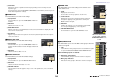
Table Of Contents
- How to Use This Reference Manual
- Contents
- Function Tree
- SELECTED CHANNEL section
- Channel Strip section
- Input and output patching
- Input channels
- Signal flow for input channels
- Specifying the channel name, icon, and channel color
- Making HA (Head Amp) settings
- Sending the signal from an input channel to the STEREO/MONO bus
- Added pan function (Monaural input channels only)
- Sending a signal from an input channel to a MIX/ MATRIX bus
- Channel name display indication
- Correcting delay between channels (Input Delay)
- Surround output for input channels
- Channel library operations
- OUTPUT channels
- Signal flow for output channels
- Specifying the channel name, icon, and channel color
- Sending signals from MIX channels to the STEREO/ MONO bus
- Sending signals from MIX channels and STEREO/ MONO channels to MATRIX buses
- Correcting delay between channels (Output Delay)
- Using the PORT TO PORT function
- Channel library operations
- EQ and Dynamics
- Channel Job
- Scene memory
- Monitor and Cue functions
- Talkback and Oscillator
- Meters
- Graphic EQ, Parametric EQ, effects, and Premium Rack
- I/O devices and external head amps
- MIDI
- Recorder
- Setup
- About the SETUP screen
- User settings
- Preferences
- USER DEFINED keys
- Functions that can be assigned to USER DEFINED keys
- USER DEFINED knobs
- Functions that can be assigned to USER DEFINED knobs
- Custom fader bank
- Console Lock
- Saving and loading setup data to and from a USB flash drive
- Remount function to USB flash drives
- Word clock and slot settings
- Using cascade connections
- Basic settings for MIX buses and MATRIX buses
- Switching the entire phantom power supply on/ off
- Specifying the brightness of the touch screen, LEDs, channel name displays, and lamps
- Setting the date and time of the internal clock
- Setting the network address
- Setting up the Dante audio network
- Dante Device Lock
- Support for Dante Domain Manager
- Using GPI (General Purpose Interface)
- Help function
- Other functions
- Initializing the unit to factory default settings
- Adjusting the detection point of the touch screen (Calibration function)
- Adjusting the faders (Calibration function)
- Fine-tuning the input and output gain (Calibration function)
- Adjusting the LED color (Calibration function)
- Adjusting the brightness of the channel name display
- Adjusting the contrast of the channel name display
- Initializing the Dante audio network settings
- Update procedure for NAME SUB CPU firmware
- Update function to Dante firmware
- Warning/Error Messages
- Index
- Data List
- EQ Library List
- DYNAMICS Library List
- Dynamics Parameters
- Effect Type List
- Effects Parameters
- Premium Rack Processor Parameters
- Parameters That Can Be Assigned to Control Changes
- NRPN Parameter Assignments
- Mixing Parameter Operation Applicability
- MIDI Data Format
- Input/Output Characteristics
- Electrical Characteristics
- Mixer Basic Parameters
- Pin Assignment
- MIDI Implementation Chart

SELECTED CHANNEL section
V5 Reference Manual
7
If the destination bus channels are two mono channels:
1 SEND knob
Adjusts the send level to the corresponding bus.
2 PRE indicator
Indicates the send point of the corresponding bus. If the PRE button on the MIX SEND
8ch screen is turned ON, this PRE indicator will be turned on.
3 ON button
Switches the send signal to the corresponding bus on or off.
If the destination bus is a stereo channel:
1 SEND/PAN knob
The right-hand knob adjusts the level of the signal sent to a pair of bus channels (even-
numbered and odd-numbered). The left-hand knob adjusts the pan and balance of the
same signal.
2 PRE indicator
Indicates the send point of the corresponding bus. If the PRE button on the MIX SEND
8ch screen is turned ON, this PRE indicator will be turned on.
3 ON button
Switches the send signal to the two buses on or off.
NOTE
• If the indices of a SEND/PAN knob are white, the send point is assigned as PRE; if the indices
are black, it is assigned as POST.
• If the send point is PRE, you can specify the PRE point as either VARI [PRE EQ] or VARI [PRE
FADER] in the BUS SETUP popup that appears when you press the SETUP button BUS
SETUP button.
• If the type of the destination bus is set to FIXED, controllers
1–2 mentioned above will not be
displayed. The send level will be fixed at nominal level, and the send point will be fixed at POST
FADER. For details, see “Basic settings for MIX buses and MATRIX buses” on page 240.
• Press the SEND knob or PAN knob on screen to open the SEND 8ch window.
When using CUE B
Indicates that channels 7 and 8 on the MATRIX
bus are combined with CUE B.
NOTE
For details about how to use CUE B, see the
CUE screen (When configuring CUE B).
GAIN/PATCH field
This field enables you to make HA (head amp) analog or digital gain settings. You can also
view the operational status of the head amp.
1 GAIN knob
Sets the analog gain/digital gain of the head amp.
Press the knob to open the GAIN/PATCH 1ch
window.
2 GC indicator
Indicates the fixed gain value output to the audio
network if the Gain Compensation function is
turned on.
3 OVER indicator
Warns you when the signal is clipping.
4 Ø (Phase) indicator
Indicates the status of the phase setting.
5 +48V indicator
Indicates the phantom power (+48V) on or off status for the head amp.
6 HPF ON indicator
Indicates the HPF on/off status of the external head amp.
7 AG-DG LINK indicator
Indicates a link between the analog gain and digital gain of the head amp.
8 Digital/Analog gain value
If analog gain is assigned to the GAIN knob, the digital gain value is shown here. If digital
gain is assigned to the GAIN knob, the analog gain value is shown here.
NOTE
• For an input channel that is patched to an input that has no head amp, 1, 2, 5, 6, and 7
will not be shown. For an output channel,
1–7 will not be shown.
• If GAIN KNOB FUNCTION is set to DIGITAL GAIN in the USER SETUP PREFERENCE
screen, the digital gain knob will appear for
1, and 2, 5, 6, and 7 will not be shown. For
details, refer to “Making HA (Head Amp) settings” on page 28.
1
2
3
1
2
3
3
5
876
1
4
2