
User Manual

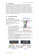
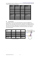


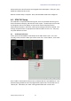


Table Of Contents

CL/QL External Surround Metering Guide
www.yamahaproaudio.com
3
Pin configuration table for AES/EBU connection from Yamaha MY8-AE96 or MY16-AE
to TM7, using 25-pin D-sub connectors:
Yamaha
MY8-AE96
TM7
HW20711
Output 1+
5
24
Input 1+
Output 1-
18
12
Input 1-
Gnd
22
25
Gnd
Output 2+
6
10
Input 2+
Output 2-
19
23
Input 2-
Gnd
23
11
Gnd
Output 3+
7
21
Input 3+
Output 3-
20
9
Input 3-
Gnd
24
22
Gnd
Output 4+
8
7
Input 4+
Output 4-
21
20
Input 4-
Gnd
25
8
Gnd
2.2 GPI Connection
It is possible to use the CL or QL User Defined Keys to control the RTW device’s
display settings. This requires a GPI connection. Both devices use different types of
connector, so a custom cable will need to be manufactured. The RTW device uses an
RJ11 connector with 6 pins (6p6c type). The Yamaha console uses a 15-pin D-sub
connection (the type with 2 rows of pins, not the VGA type with 3 rows). Below is
the connection table.
Yamaha
CL/QL
15-pin D-
sub
RTW TM7
RJ11 6p6c
Gnd
4
1
Gnd
GPI out 1
1
2
GPI in 1
GPI out 2
9
3
GPI in 2
GPI out 3
2
4
GPI in 3
GPI out 4
10
5
GPI in 4
GPI out 5
3
6
GPI in 5
(Pin 1 is on the left-side of the RJ11 socket while looking at the
rear panel of the TM7).