UCAGBRT LPX-500 Home Cinema Projector an (English) 403256900 OWNER'S MANUAL
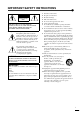
IMPORTANT SAFETY INSTRUCTIONS CAUTION RISK OF ELECTRIC SHOCK DO NOT OPEN CAUTION: TO REDUCE THE RISK OF ELECTRIC SHOCK, DO NOT REMOVE COVER (OR BACK). NO USER-SERVICEABLE PARTS INSIDE. REFER SERVICING TO QUALIFIED SERVICE PERSONNEL.
COMPLIANCE INFORMATION STATEMENT (DECLARATION OF CONFORMITY PROCEDURE) Responsible Party: Address: Telephone: Fax: Type of Equipment: Model Name: Yamaha Electronics Corporation 6660 Orangethorpe Avenue Buena Park, CA90620 714-522-9105 714-670-0108 Projector LPX-500 This device complies with Part 15 of the FCC Rules.
Caution: Read this before operating this unit. • To assure the finest performance, please read this manual carefully. Keep it in a safe place for future reference. Installation • • • • • • Install this unit in a well-ventilated, cool, dry, clean place with at least 10 cm clearance on the top, right and left, and at the back of this unit — away from direct sunlight, heat sources, vibration, dust, moisture, and/or cold.
Notations used in this Owner’s Manual Indications Indicates procedures where personal injury or damage to the projector may occur if the procedures are not followed correctly. Indicates additional information and points which may be useful to know regarding a topic. Indicates that an explanation of the underlined word or words in front of this symbol appears in the glossary of terms. Refer to the “Glossary” in the “Appendix”. (p.61) Procedure Indicates operating methods and the order of operations.
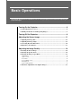
Turning On the Projector ...................................................................................6 Connecting the Power Cord ..................................................................................... 6 Turning On the Power and Projecting Images ......................................................... 7 Turning Off the Projector ...................................................................................9 Adjusting the Screen Image ...............................................
Notes on Handling and Storage Be sure to observe the following precautions to avoid malfunctions, operating errors or damage to the projector. Notes on Handling and Storage • Do not set up the projector near high-voltage electrical wires or sources of magnetic fields. These may interfere with correct operation. • Do not touch the lens with bare hands. • • • • • If fingerprints or grease get onto the lens, it can interfere with the quality of the projected images.
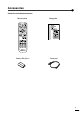
Accessories Check the included accessories Remote control Battery LR6 (AA) x 2 Setup guide Power cord 3
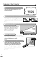
Features of the Projector 1280 Adoption of a wide 1280 x 720 dot panel This panel allows high-definition images to be reproduced accurately. 720 Adoption of a special high-resolution DCDi video circuit developed by Faroudja. This circuit greatly reduces the jagged edges that resulted from conventional progressive conversion, to produce much smoother and natural movement. (p.30) Adoption of a short focal-length lens that can project onto 80-inch screens at distances of 2.5m (8.2 ft.
Basic Operations This chapter describes basic operations such as turning the projector on and off and adjusting the projected images. Turning On the Projector.................................................................. 6 Connecting the Power Cord ........................................................................................6 • Turning On the Power and Projecting Images..........................................................7 • Turning Off the Projector....................................
Turning On the Projector This section describes the procedure from turning on the power to projecting images. Be sure to read the Safety Instructions in this manual for details on safe handling when using the projector. Connecting the Power Cord Procedure 1 Check that the power is turned off for the projector and all components connected to the projector. 2 Connect the computer or other video source to the projector. Refer to the Setup Guide. 3 Remove the lens cap.
Connecting the Power Cord Turning On the Power and Projecting Images Turning On the Power and Projecting Images Procedure 1 2 Lights green Projector Remote control Basic Operations Turn on the power for all equipment connected to the projector. For a video source, press the [Play] button at the video source to start playback if necessary. Check that the indicator on the projector has stopped flashing and lights orange.
Turning On the Projector • If only one signal source has been connected, the signals from that source will be projected without needing to press one of the above buttons. • If video signals are being input to several input ports simultaneously, interference between the various signals may occur, and this may cause interference in the projected images. If this happens, turn off the power supply or disconnect the video equipment which is not currently being used.
Turning Off the Projector Follow the procedure below to turn off the power of the projector. Procedure 1 Please Press To Power Off Key Again 3 Projector Remote control Basic Operations 2 Turn off the power for the signal sources that are connected to the projector. Check that the power for all connected components has been tuned off. Press the [STANDBY/ON] button on either the remote control or the projector's control panel. The confirmation message shown at left will appear.
Turning Off the Projector 5 If not using the projector for long periods of time, turn off the main power switch at the rear of the projector. Do not turn off the main power switch at the rear of the projector while the cool-down is in progress. If the main power switch is turned off before cool-down is complete, wait for the lamp to cool down (normally about one hour is required) before turning the power back on again.
Adjusting the Screen Image Adjusting the Image Size Correcting Keystone Distortion Adjusting the Image Angle Displaying a Test Pattern You can adjust the screen image in order to obtain the best possible picture. Adjusting the Image Size The size of the projected image is basically determined by the distance from the projector to the screen. (Refer to the Setup Guide.) The following procedures explain how to adjust the screen image once the projector itself has been set up.
Adjusting the Screen Image Correcting Keystone Distortion If the projector is set up so that it is at an angle to the screen, a type of distortion known as "keystone distortion" may occur. Keystone correction can be carried out if the angle of the projector is within a range of approximately 15° vertically from the perpendicular. Approx. 15° above Approx. 15° below 15° 15° Procedure While holding down the [SHIFT] button on the projector's control panel, press the or button.
Adjusting the Image Size Correcting Keystone Distortion Adjusting the Image Angle Displaying a Test Pattern Displaying a Test Pattern When setting up the projector, you can project a test pattern onto the screen and use this test pattern to adjust the projected images before a video source has been connected. The following two types of test pattern are available. • Crosshatch • Basic Operations This can be used to adjust the focus and correct keystone distortion.
Adjusting the Image Quality The quality of the screen images can be adjusted as follows. Focusing the Screen Image Turn the focus ring to adjust the image focus. Procedure • If the surface of the lens is dirty or misted over as a result of condensation, it may not be possible to adjust the focus correctly. If this happens, clean or de-mist the lens. (p.46) • If the projector is positioned outside the normal projecting range of 0.9 - 13 m (2.9 - 42.6 ft.
Focusing the Screen Image Selecting the Image Aspect Ratio Selecting the Picture Mode Automatic Adjustment of Computer Images Selecting the Image Aspect Ratio Input signal Video (SDTV ) Video (HDTV ) Computer (SVGA Computer (XGA Normal Squeeze Zoom Zoom -Subtitle- O O O Through Squeeze Through O O O - O - - - O (720p only) or lower) O - O - O - or higher) O - O - - - Basic Operations The aspect ratio for projected images can be selected from the following five types of
Adjusting the Image Quality Squeeze mode When images in squeeze mode are displayed on a 4:3 TV screen Viewed using the projector Use this setting if the connected video source has a 16:9 output mode (Squeeze mode). If images in squeeze mode are viewed on a 4:3 TV screen, the images are compressed horizontally and elongated vertically. If Squeeze mode is selected on the projector, the images are projected correctly in their native wide-screen (16:9) format.
Focusing the Screen Image Selecting the Image Aspect Ratio Selecting the Picture Mode Automatic Adjustment of Computer Images Through mode If the input signal resolution is 1280 x 720 dots or less, the images are projected onto the screen with the input signal resolution unchanged. Because of this, the size of the displayed images will change depending on the input resolution. The picture quality will be the clearest for portions of the image that have not been resized horizontally or vertically.
Advanced Operations This chapter describes functions for enhancing the projection of images, and how to use the menus. Functions for Enhancing Projection ............................................. 20 • Using the Menus .........................................................................................................20 • Displaying and Operating Full Menus ............................................................................................20 • Displaying and Operating Line Menus ..........
Functions for Enhancing Projection This section describes the various useful functions that can be used to enhance projection. Function Summary Reference page Black level adjustment Adjusts the brightness of dark shades. p.23 White level adjustment Adjusts the brightness of light shades. p.23 Color Temp., Flesh Tone and Color Balance Adjusts the hues of light shades to the desired level. p.
Using the Menus Memory Save Description of Functions Image ESC 4 Signal Black Level White Level Saturation Hue Picture Mode Color Temp. Flesh Tone Color Balance Sharpness Memory Save Reset Image :Return Image :Return Info 0 0 0 0 A B 6700K 0 C PC sRGB 3 4 0 2 1 :Select Signal Black Level White Level Saturation Hue Picture Mode Color Temp.
Functions for Enhancing Projection Displaying and Operating Line Menus Procedure 1 Press the button on either the projector's control panel or the remote control while the full menu is being displayed. The line menu appears. Projector Black Level Remote control 0 2 Select an item to be set. If using the projector's control panel, press the and buttons. If using the remote control, press the button up and down. Projector Remote control 3 The line menu item changes when a button is pressed.
Using the Menus Memory Save Description of Functions 5 Exit the menu display. Press the [MENU] or [ESCAPE] button on either the projector's control panel or the remote control. If you do not press a button for 5 seconds while a line menu is displayed, the line menu disappears automatically. Projector Remote control Description of Functions This section describes commonly-used functions.
Functions for Enhancing Projection Color temperature, flesh tone and color balance adjustment This adjusts the hues of light shades to the desired hues. Three modes are available, for adjusting Color Temperature , flesh tones and each individual RGB color. These adjustments are cumulative, so first carry out the basic "Color Temp." and "Flesh Tone" adjustments while referring to the graph below, and then make fine adjustments using the "Color Balance" command. Use the "Color Temp.
Using the Menus Memory Save Description of Functions Image Signal Black Level White Level Saturation Hue Picture Mode Color Temp. Flesh Tone Color Balance Sharpness Memory Save Reset Image -,+ :Select 3 Image Info 0 0 0 0 A B 6700K 0 C PC sRGB 3 4 0 1 2 5 6 Select "Memory Save" from the submenu of the "Image" menu. If using the projector's control panel, press the and buttons. If using the remote control, tilt the button up and down.
Using the Menu Functions The menus are used to make various adjustments and settings. There are two types of projector's menus used: full menus and line menus. The following pages explain how to change the settings for the various menu commands, using full menus as illustrations. Full menus consist of a main menu and sub-menus in a hierarchical structure. Refer to "Using the menus" (p.20) for details on carrying out the various menu operations.
Image Sub-menu Setup menu Signal menu Info menu Default setting Function Picture Mode Corrects the vividness of the image color. You can select from five different quality settings depending on the surroundings. :Ideal for enjoying presentations in a natural atmosphere. •A :Ideal for enjoying presentations such as movies which have large •B numbers of dark scenes. :Ideal for projecting images with greater modulation and intensity.
Using the Menu Functions Computer (DVI, INPUT A (RGB), INPUT B (RGB)) RGB Image DVI Signal Black Level White Level Tracking Sync. Picture Mode Color Temp. Flesh Tone Color Balance Sharpness Memory Save Reset Image -,+ :Select 28 Image Info 0 0 0 0 A B 7500K 3 C PC sRGB 0 1 2 3 4 5 Signal Black Level White Level Picture Mode Color Temp.
Image Sub-menu Setup menu Signal menu Info menu Default setting Function Color Temp. Allows lighter colors to be adjusted so that they range from having a red tinge to having a blue tinge. (p.24) When the color temperature is lower, the red content is greater and color tones appear softer. When the color temperature is higher, the blue content is greater and color tones appear fresher. 7500K Flesh Tone The "Flesh Tone" setting adjusts the green component of image signals. (p.
Using the Menu Functions Signal Menu Image Signal Progressive Noise Reduction Position Video Signal INPUT A Signal INPUT B Signal Setup Level Zoom Subtittle -,+ :Select 30 Video NR1 Auto Component Component 0% Info Film/Auto NR2 RGB RGB 7.5% :Enter Main menu Signal Setup Off Off Sub-menu Function Default setting Progressive (Adjustment is only possible when composite, S-Video, 480i and 576i signals are being input.
Main menu Signal Image menu Setup menu Signal menu Info menu Default setting Sub-menu Function Setup Level (Adjustment is only possible when NTSC, 480i/p, 576i/p, 720p and 1080i signals are being input.) This setting does not normally need to be changed when connecting the projector to video equipment that is designed for use within Japan.
Using the Menu Functions Main menu Setup 32 Default setting Sub-menu Function Auto Power Off This sets whether the projector's power turns off automatically or not when the signal from the input source that was selected using the [INPUT] button stops being input. Setting value range : Off, 30 min., 60 min.
Image menu Set up menu Signal menu Info menu Info Menu • • The “Info” menu displays the settings for the input source for the images being projected, and also shows the lamp status. The "Lamp" shows times between 0 and 10 hours as 0H. Times greater than 10 hours appear in units of one hour.
Using the Menu Functions Main menu Info Sub-menu Input Signal Displays the input signal settings. Frequency Displays the horizontal and vertical scanning frequencies. Sync Polarity Displays the synchronization 34 Default setting Function polarity. - Sync Mode Displays the synchronization attributes. - Resolution Displays the input resolution. - Refresh Rate Displays the refresh rate.
Troubleshooting This chapter describes troubleshooting procedures for the projector. When Having Some Trouble........................................................... 36 When the Indicators Provide No Help ...........................................
When Having Some Trouble If you are having a problem with the projector, first check the projector's indicators. The projector is provided with the following three indicators. These indicators alert you to problems with projector operation. indicator LAMP/COVER indicator TEMP/FAN indicator The following tables show what the indicators mean and how to remedy problems that they indicate.
Indicator status Red Red Orange Projector status High temperature inside projector (overheating) High-speed cooling in progress Problem and remedy The lamp will turn off automatically and projection will stop. Wait for about 5 minutes without operating the projector. After 5 minutes have elapsed, the projector's cooling fan will stop. When the cooling fan stops, turn off the main power switch and then turn it back on again. If the projector overheats, check the following two points.
When the Indicators Provide No Help If any of the following problems occur and the indicators do not offer a solution, refer to the pages given for each problem. No images appear p.38, p.39 Images appear dark p.42 Poor image quality p.40 Images appear green p.42 Only part of the image is displayed (Large/small) p.41 The remote control does not work p.42 The image colors are not right The power does not turn off p.41 p.
Condition No images appear (Messages do appear) “Not Supported” message appears on the screen. “No Signal”message appear on the screen. Remedy Does the input signal setting match the connected source? Use the “Video Signal”, “INPUT A Signal” or “INPUT B Signal” commands in the “Signal” menu to set the signal format that matches the signal from the connected equipment. “Signal” - “Video Signal”, “INPUT A Signal”, “INPUT B Signal” (p.
When the Indicators Provide No Help Condition Poor image quality • The image is fuzzy • Part of the image is out of focus • The whole image is out of focus • The image is distorted • The image contains interference Probable cause Remedy Has the focus been adjusted correctly? Adjust the focus. (p.14) Has the front adjustable foot been adjusted so that the projection angle is too big? Adjust the projection angle. (p.11) If the projection angle is too big, the image will be out of focus vertically.
Condition • Image is too large (Only part of the image is displayed) • Image is too small Probable cause Remedy The display mode (aspect ratio ) setting may not be selected correctly. Press the [ASPECT] button on either the remote control or the projector's control panel. (p.15) Has the "Position" setting been adjusted correctly? Use the “Position” command in the “Signal” menu to adjust. (p.
When the Indicators Provide No Help Condition Images appear dark Probable cause Remedy Is the lamp due for replacement? Replace the lamp with a new one. (p.48, 49) If the LAMP/COVER indicator is flashing orange, it means that the lamp will soon be due for replacement. When the lamp is nearly due for replacement, the image will become darker and the tint will become poorer.
Condition The power does not turn off (after the [STANDBY/ON] button is pressed) Remedy indicator still orange? When the main power switch at the rear of the projector is turned off, the indicator switches off. This projector is designed so that the indicator remains lit even when after the power has been turned off. Is the fan operating? After the [STANDBY/ON] button on either the remote control or the projector's control panel is pressed to turn off the power, the cool-down period starts.
Appendices This chapter provides information on maintenance procedures to ensure the best level of performance for the projector for a long time. Maintenance..................................................................................... 46 • Cleaning.......................................................................................................................46 • Cleaning the Projector Case ......................................................................................................
Maintenance This section describes maintenance tasks such as cleaning the projector and replacing consumable parts. Cleaning You should clean the projector if it becomes dirty or if the quality of projected images starts to deteriorate. Be sure to read the Safety Instructions in this manual for details on safe handling of the projector during cleaning. Cleaning the Projector Case Clean the projector case by wiping it gently with a soft cloth.
Cleaning Replacing Consumables Replacing Consumables This section describes how to replace the lamp and the air filter. Lamp Replacement Period It is time to replace the lamp when: • The message "Lamp Replace" appears on the screen when projection starts. The message appears for 30 seconds, and disappears again after 30 seconds have passed. A message will be displayed. • The LAMP/COVER indicator flashes orange or lights red. Lamp indicator flashes orange or lights red.
Maintenance Replacing the Lamp • If the lamp stops working and needs to be replaced, there is the danger that the lamp may break when handled. If replacing the lamp of a projector which has been installed to the ceiling, you should remove the projector from the ceiling before replacing the lamp. If the projector cannot be removed from the ceiling, you should always assume that the lamp is broken and handle it with extreme care during removal.
Cleaning Replacing Consumables 5 Install the new lamp. Hold the lamp so that it faces the correct way to fit into the projector, and then insert the lamp until it clicks into place and tighten the two fixing screws. 6 Install the lamp cover. Close the lamp cover, slide it toward the rear of the projector, and then push the front part downward until it clicks into place. • Install the lamp securely. For safety, the lamp will turn off automatically when the lamp cover is opened.
Maintenance 3 Reset Lamp Timer Execute? No Reset the lamp operating time. Select “Yes”, and then press the on either the projector's control panel or the remote control. Yes Replacing the Air Filter Procedure 1 2 3 Turn off the power switch at the rear of the projector, and then disconnect the power cord. (p.9) Put your finger into the recess in the air filter hook, and lift up the air filter to remove it.
Optional Accessories The following optional accessories are available for purchase if required. This list of optional accessories is current as of July 2002. Details of optional accessories are subject to change without notice. Spare lamp PJL-5015 Use as a replacement for spent lamps. Ceiling mount (for low ceilings) * PMT-L21 Use when installing the projector to a low ceiling. Ceiling mount (for high ceilings) * PMT-H25 Use when installing the projector to a high ceiling.
List of Supported Signal Resolutions Component Video Input Units: dots Aspect Signal Resolution Normal (Default) SDTV (480i, 60Hz) 640 × 480 640 × 360 (When zoomed) 960 × 720 (4:3 aspect) SDTV (576i, 50Hz) 768 × 576 768 × 432 (When zoomed) SDTV (480p) Zoom -Subtitle- Through Squeeze Through 1280 × 720 1280 × 720 (16:9 aspect) (16:9 aspect) 1280 × *** (Variable) 590 × 442 (4:3 aspect) 786 × 442 (16:9 aspect) 960 × 720 (4:3 aspect) 1280 × 720 1280 × 720 (16:9 aspect) (16:9 aspect) 1280 × ***
Component Video Input RGB Input Composite Video/S-Video Input RGB Input Units: dots Signal Resolution (When zoomed) Aspect Normal (Default) Squeeze Zoom Zoom -Subtitle- Through Squeeze Through PC98 640 × 480 (640 × 360) 1152 × 720 1280 × 720 640 × 400 640 × 350 70 640 × 350 (640 × 350) 1280 × 700 1280 × 700 640 × 350 VGA 60 *, SDTV (480p) 640 × 480 (640 × 360) 960 × 720 (4:3 aspect) VGA 72/75/85, iMac_VGA 640 × 480 (640 × 360) 960 × 720 1280 × 720 640 × 480 SVGA 56/ 60*/72/75/85
Specifications 54 Product name LPX-500 Home cinema projector Dimensions 409 (W) x 111 (H) x 281 (D) mm (16.1 (W) x 4.37 (H) x 11.06 (D) inches) (not including protruding parts) Panel size 2.2mm (0.87 inches) Display method Polysilicon TFT active matrix Drive method Full-line 12-phase block sequential writing Resolution 921,600 pixels (1280 (W) x 720 (H) dots) x 3 Focus adjustment Manual Zoom adjustment Manual (approx. 1:1.35) Lamp (light source) UHP lamp, 150 W, Model No.
Safety USA UL1950 3rd Edition Canada CSA C22.2 No.950 -95 (cUL) European Community The Low Voltage Directive (73/23/EEC) IEC60950 2nd Edition, +Amd.1, +Amd.2, +Amd.3, +Amd.
Appearance 281 (11.06) 111 (4.37) 125 (4.92) 409 (16.
Part Names and Functions Front/Top Rear Control panel Base Remote control Front/Top Focus ring (p.14) Adjusts the image focus. Zoom ring (p.11) Adjusts the image size. Lamp cover (p.48) Open this cover when replacing the lamp unit inside the projector. Lamp cover opening switch (p.48) Slide this switch to unlock the lamp cover when removing it. Control panel (p.58) Air exhaust vent Lens cap Attach when not using the projector to prevent the lens from becoming dirty or damaged.
Part Names and Functions Control Panel [MENU] button (p.20) The menus turn on and off each time the [MENU] button is pressed. and buttons (p.12, 21, 22, 25) Press to select an item in the menu or help menu. Press and hold the [SHIFT] button while pressing these buttons to correct keystone distortion of images. button (p.21, 22, 25) Displays the line menu. Pressing the button while viewing the menu or the online help selects the menu item and proceeds to the next display. indicator (p.
Front/Top Rear Control panel Base Remote control Rear TRIGGER OUT port When the projector power is turned on, 12 V DC is output from this port. When the projector's power is turned off, the output becomes 0 V to communicate the projector's power ON/OFF status to an external device. Remote control lightreceiving area (Setup Guide) Receives signals from the remote control. RS-232C port Connects the projector to a computer using an RS-232C cable.
Part Names and Functions Remote Control Remote control lightemitting area (Setup Guide) Outputs infrared remote control signals. [AUTO] button (p.17) Automatically adjusts computer images to the optimum images. [ESCAPE] button (p.21, 22) If pressed while a menu is being displayed, the display returns to the next-highest level. [LIGHT] button (Setup Guide) When slid up or down, the [STANDBY/ON], [PATTERN], [AUTO], [MENU], [ESCAPE], [ASPECT] and [PICTURE] buttons illuminate for 10 seconds.
Glossary 3-2 pull-down detection-type IP conversion This function directly converts image sources that have been recorded in the same 24-frame format used for movies into 60-frame progressive signals. This allows data such as DVD software that has been recorded in 24-frame format to be played back on large screens with more natural and accurate reproduction, without any loss of image quality from the original movie. Aspect ratio The ratio between an image's length and its height.
Glossary 62 Interlaced A method of image scanning whereby the lines in a single image are divided into two sections or "fields". The signal bandwidth used for interlaced scanning is approximately half that required for progressive scanning when images with the same still picture resolution are broadcast. Offset The adjustment of minute changes in color that occur as result of factors such as differences in the equipment used to display images.
Index indicator.............................. 36, 58 A Adjustment Foot ................................ 11 Appearance ........................................ 56 Aspect ratio ........................................ 15 Automatic Adjustment of Computer Images ...................................... 17, 60 Auto power off................................... 32 B Battery compartment cover (Remote control) ........................... Setup Guide Battery replacement period (Remote control) ......................
All rights reserved. No part of this publication may be reproduced, stored in a retrieval system, or transmitted in any form or by any means, electronic, mechanical, photocopying, recording, or otherwise, without the prior written permission of YAMAHA CORPORATION. No patent liability is assumed with respect to the use of the information contained herein. Neither is any liability assumed for damages resulting from the use of the information contained herein.
YAMAHA YAMAHA YAMAHA YAMAHA YAMAHA YAMAHA YAMAHA ELECTRONICS CORPORATION, USA 6660 ORANGETHORPE AVE., BUENA PARK, CALIF. 90620, U.S.A. CANADA MUSIC LTD. 135 MILNER AVE., SCARBOROUGH, ONTARIO M1S 3R1, CANADA ELECTRONIK EUROPA G.m.b.H. SIEMENSSTR. 22-34, 25462 RELLINGEN BEI HAMBURG, F.R. OF GERMANY ELECTRONIQUE FRANCE S.A. RUE AMBROISE CROIZAT BP70 CROISSY-BEAUBOURG 77312 MARNE-LA-VALLEE CEDEX02, FRANCE ELECTRONICS (UK) LTD. YAMAHA HOUSE, 200 RICKMANSWORTH ROAD WATFORD, HERTS WD1 7JS, ENGLAND SCANDINAVIA A.
Essen SET UP GUIDE English-hyoshi Before Using the Remote Control Inserting the Batteries Battery Replacement Period and Using the Remote Control Remote Control Operating Range Setup Screen Size and Setting-up Distance Setting-up Methods Connecting to a Video Source Connecting to a Computer Printed in Japan (English) 403257000
Essen SET UP GUIDE English-01 Inserting the Batteries Before Using the Remote Control 1 The batteries are not inserted into the remote control at the time of purchase, so you need to insert them before the remote control can be used. 1 Remove the battery compartment cover. While pressing the cover here, lift the cover up. 2 3 Insert the batteries. Make sure the polarities of the batteries are correct. Replace the battery compartment cover.
Essen SET UP GUIDE English-02 Battery Replacement Period and Using the Remote Control Battery Replacement Period If the remote control becomes slow in responding or if it stops working, the batteries may be spent. If this happens, replace the batteries with fresh ones. Guide for battery replacement: Approximately 3 months if used for 30 minutes per day * The replacement period given above may vary depending on the amount of usage and the ambient conditions.
Essen SET UP GUIDE English-03 Remote Control Operating Range Use the remote control within the ranges indicated below. If the distance or angle between the remote control and the remote control light-receiving area is outside the normal operating range, the remote control may not work. Operating distance Operating angle Approx. 7 m (23 ft) Approx. 30˚ vertically and horizontally Approx. ±30˚ horizontally Approx. 7m (23 ft) Approx. 30˚ Approx. 30˚ Approx. 30˚ Approx. 30˚ Approx.
Essen SET UP GUIDE English-04 Screen Size and Setting-up Distance Setup The distance between the projector and the screen (16:9) determines the actual image size. Recommended distance : 0.9m - 13.0m (2.9 - 42.6 feet) While referring to the table below, position the projector so that the image size is smaller than the screen size. Distance in Fig. A below (cm (feet)) Screen size (cm (feet)) Approximate projection distance* (m (feet)) 80" (177 × 100 (5.8 × 3.2)) 90" (200 × 112 (6.5 × 3.6)) 2.5 – 3.
Essen SET UP GUIDE English-05 Setting-up Methods The projector supports the following 4 projection methods, allowing you to choose the best method for displaying your images. After setting up the projector, refer to the OWNER'S MANUAL for details on turning on the power and adjusting settings such as the screen size. ( "Basic Operations" in OWNER'S MANUAL) Be sure to read "Caution" in OWNER'S MANUAL for details on safe handling when setting up the projector.
Essen SET UP GUIDE English-06 Connecting to a Video Source Turn off the power for both the projector and the video source before connecting them. If the power for either device is on at the time of connection, damage may result. Check the shapes of the cable connectors and the device ports before making the connections. If you try to force a connector to fit a device port with a different shape or number of terminals, a malfunction or damage to the connector or port may result.
Essen SET UP GUIDE English-07 Projecting Composite Video Images To VIDEO port (yellow) To Video output port (yellow) RCA video cable (yellow) Projecting S-Video Images To S VIDEO port To S-Video output port S-Video cable 7 Depending on the combination of the VCR and the video cassette used for the playback, the color of the projected images may flicker or the correct color may not be displayed. In this case, select "Signal" and set "Progressive" to OFF for improving the playback quality.
Essen SET UP GUIDE English-08 Projecting RGB Video Images If connecting to the INPUT A port To RGB output port Green Blue Red To INPUT A port Computer cable If connecting to the INPUT B port To RGB output port To INPUT B port Computer cable If more than one peripheral device is being connected to the projector, make the connections and then change the "INPUT A Signal" or "INPUT B Signal" commands in the "Signal" menu to "RGB" to match the signals from these devices.
Essen SET UP GUIDE English-09 Connecting to a Computer 9 Turn off the power for both the projector and the computer before connecting them. If the power for either device is on at the time of connection, damage may result. Check the shapes of the cable connectors and the device ports before making the connections. If you try to force a connector to fit a device port with a different shape or number of terminals, damage to the connector or port may result.
Essen SET UP GUIDE English-10 If connecting using a computer cable To INPUT B port To monitor port (video port) Computer cable If connecting more than one projector together, make the connection and then use the menus to change the "INPUT B Signal" setting in the "Signal" menu to "RGB". ("Signal" menu in OWNER'S MANUAL) If video signals are being input to several input ports simultaneously, interference between the various signals may occur, and this may cause interference in the projected images.
Esssen SET UP GUIDE English-11 If the computer is equipped with a DVI-D output port To DVI-D port To DVI-D port (video port) DVI-D cable (digital) Do not bind the power cord together with the computer cable or DVI-D cable (digital), otherwise it may cause interference in the projected images or operating errors. Two kinds of DVI cable are available. Use a DVI-D cable to connect to this projector.