M7CL V3 Editor Version 3.5 Owner’s Owner’s Manual Manual Special Notices Contents • The software and this owner’s manual are the exclusive copyrights of Yamaha Corporation. • Copying of the software or reproduction of this manual in whole or in part by any means is expressly forbidden without the written consent of the manufacturer. • Copying of the commercially available music sequence data and/or digital audio files is strictly prohibited except for your personal use.
Getting Started Overview of M7CL V3 Editor M7CL V3 Editor (hereinafter called “M7CL Editor” in this document) enables you to remotely control a Yamaha M7CL mixing console (Version 3) (such as M7CL-48ES, M7CL-48, or M7CL-32; hereinafter collectively called “M7CL” in this document). M7CL Editor also enables you to save the parameter settings on your computer. To use M7CL Editor, you must first perform the following operations: 1 Start and configure Studio Manager. 2 Start and configure M7CL Editor.
C Channel Select / Sends On Fader This checkbox enables you to specify whether or not the M7CL console and M7CL Editor are linked to each other for the following operations: • Selecting channels • Switching between normal mode and SENDS ON FADER mode • Switching between MIX and MATIRX in SENDS ON FADER mode If you do not check the box, the M7CL console and M7CL Editor will operate independently. D Fast Sync This allows synchronization to be speed up, reducing the time required.
❏ Mixer Setup To open the Mixer Setup dialogbox, choose [Mixer Setup] from the [File] menu. 1 2 A Mix Bus Setup Here you can make settings relating to the MIX buses. Signal Type: Choose either MONOx2 or STEREO for each two adjacent odd-numbered/even-numbered MIX buses. Bus Type/Send Point: Choose either VARI (PRE FADER) or VARI (PRE EQ) or FIXED for each two adjacent odd-numbered/even-numbered MIX buses.
❏ Creating a user key To open the Create User Key dialogbox, choose [Create User Key] from the [File] menu. This creates a user key (with “.M7U” file name extension) that can be read from a USB storage device by the M7CL console to automatically set user-specific parameters. 1 3 2 5 6 4 7 8 L 9 M J N K O P A User Name Specify the name of the user. You can enter up to eight single-byte alphanumeric characters. Lowercase characters will automatically become uppercase on the M7CL console.
G ACCESS PERMISSION In this area, specify the parameters that this user will be allowed to operate. H CH OPERATION INPUT, ST IN, DCA, MIX, MATRIX, ST/MONO: Select the channels whose parameters will be operable. HA: Change the operating privileges for the head amp gain and phantom power of the selected channels. PROCESSING: Change the operating privileges for overall signal processing parameters (except for fader and [ON] key) of the selected channel.
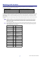
Working with Sessions All of your console’s mix settings in M7CL Editor, including Scene and library data, are called Sessions. The following table describes how to handle Sessions. Creating a new Session Opening a previously saved Session Saving the current Session Saving the current Session with a new name Choose [New Session] from the [File] menu. Choose [Open Session] from the [File] menu. Choose [Save Session] from the [File] menu. Choose [Save Session As...] from the [File] menu.
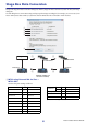
Stage Box Data Conversion To open the Stage Box Data Conversion dialog box, click the [Stage Box Data Conversion] button in the System Setup dialog box. Use this dialog box to convert HA settings and input patch settings accordingly if, for example, you want to use (on an M7CL-48ES system) data stored by a system that features SB168-ES units connected to M7CL-48 slots.
B M7CL using External HA via Slot ➞ Using Internal HA D M7CL-48ES ➞ Using External HA via Slot Converts the patch settings as follows: SLOT1 IN 1-16 →(*) INPUT 1-16 SLOT2 IN 1-16 →(*) INPUT 17-32 SLOT3 IN 1-16 →(*) INPUT 33-48 ST IN 1L-4R →(*) ST IN 1L-4R INPUT 1-16 →(*) SLOT1 IN 1-16 INPUT 17-32 →(*) SLOT2 IN 1-16 INPUT 33-48 →(*) SLOT3 IN 1-16 TALKBACK → TALKBACK SLOT1 OUT 1-16 → OMNI OUT 1-16 OMNI OUT 1-16 → SLOT1 OUT 1-16 SLOT2 OUT 1-16 → SLOT2 OUT 1-16 SLOT3 OUT 1-16
Undo/Redo Function In M7CL Editor, you can cancel the latest operation (Undo) and also cancel the cancellation of the latest operation (Redo). If you perform an Undo operation twice in a row, you can cancel the two most-recent operations. If you perform an Undo operation three times in a row, you can cancel the three most-recent operations. In this way, you can cancel multiple recent operations. The following table describes how to use the Undo/Redo function. Undo Redo Choose [Undo] from the [Edit] menu.
Window operations You can select and open each window from the [Windows] menu. For the INPUT CH window and Effect Editor window, use the sub-menu to select the channels or library you want to see. You can choose Tile or Cascade to arrange the windows within the editor. ● Tile ● Cascade In the Library window or Scene window, click the tabs located at the top of the window to switch between pages.
Synchronizing M7CL Editor When M7CL Editor starts up, the parameter settings on the console and the parameter settings in M7CL Editor may be different. Therefore, you must first match the parameter settings on the console with those in M7CL Editor. This operation is called “synchronization.” Follow the steps below to synchronize M7CL Editor. 1 Select [Synchronize], then [Re-synchronize]. The following window opens. 2 Select whether you want to transfer your settings to M7CL Editor, or vice versa.
Master window In the Master window you can synchronize to the M7CL itself, recall scenes, and display the Overview window. To open this window, choose [Master] from the [Windows] menu. ❏ CHANNEL SELECT This indicates the number and name of the channel to which your operations will apply. To switch channels, you can either click the [SELECT] button and choose from the list that appears, or you can click the left/right arrow-shaped channel select buttons.
❏ SYNC This indicates the status of connection and synchronization between M7CL Editor and the M7CL. A [ONLINE]/[OFFLINE] button 12 The ONLINE/OFFLINE status will alternate each time you click this button. This has the same function as [Synchronization] menu ➔[Offline Edit]. (➥ p.12) This indicator is shown when M7CL Editor is correctly connected to the M7CL itself. In this state, the parameters of M7LC Editor and the M7CL itself are linked.
❏ Navigation Keys Opens the corresponding window in the Overview window. NOTE These are not linked with the navigation key section on the panel of the M7CL itself. 67 8 A [17-32] button Opens the INPUT CH 17–32 window. B [1-16] button 1 Opens the INPUT CH 1–16 window. 2 C [ST IN] button 3 4 Opens the ST IN window. 5 D [DCA] button Opens the DCA window. E [STEREO] button Opens the STEREO/MONO window. F [MIX] button Opens the MIX window. G [MTRX] button Opens the MATRIX window.
Overview window INPUT CH window This window displays the mix parameters of INPUT CH 1–16, 17–32, or 33–48 (*). The parameters shown in the window can be selected from the [View] menu or the menu that appears when you right-click ( key + click) in the window. You can access this window in the following ways.
D Ø (Phase) Inverts the phase of the signal after AD conversion. E HPF (High Pass Filter) 4 Switches the high pass filter on/off. You can drag the numeric value up or down to edit the cutoff frequency. F INS (Insert) 5 Enables/disables the insert-in. 6 7 8 G D. OUT (Direct out) 9 I DYN1/DYN2 (Dynamics 1/Dynamics 2) J Enables/disables the direct output. H EQ (Equalizer) Switches the EQ on/off. The graph immediately below the button shows the approximate response of the EQ.
K PAN/TO STEREO MONO K L M N O The PAN knob adjusts the panning of the signal that is sent from the INPUT CH to the STEREO bus L/R channels (or the L/C/R channels). You can set this to the center value by holding down the (< >) key of your computer keyboard and clicking this knob. The [ST] button is an on/off switch for the signal that is sent from the INPUT CH to the STEREO bus. The [M(C)] button is an on/off switch for the signal that is sent from the INPUT CH to the MONO bus.
The numbers and alphabetical letters at the right of the fader indicate the DCA group and mute groups to which that channel belongs, and show the Recall Safe and Mute Safe status of the channel. The numbers of DCA groups to which this channel belongs are shown in yellow. The numbers of mute groups to which this channel belongs are shown in red. If this channel is set to Recall Safe, the R character is shown in green. If this channel is set to Mute Safe, the M character is shown in green.
ST IN window ( M7CL-32/M7CL-48 only) In this window you can view and edit the mix parameters of ST IN channels 1–4. The parameters shown in the window can be selected from the [View] menu or the menu that appears when you right-click ( key + click) in the window. You can access this window in the following ways.
G DYN1/DYN2 (Dynamics 1//Dynamics 2) 7 These buttons switch the two dynamics processors on/off. This is the same as the dynamics 1/dynamics 2 for INPUT CH (➥ p.17). H MIX/MATRIX SEND 8 Switches between the send indications to MIX buses 1–16 or to MATRIX buses 1–8. This is the same as the mix/matrix send for INPUT CH (➥ p.17). I BALANCE The BALANCE knob adjusts the balance of the signal that is sent from the ST IN channel to the STEREO bus L/R channels (or the L/C/R channels).
MIX window In this window you can view and edit the parameters of MIX channels 1–16. The parameters shown in the window can be selected from the [View] menu or the menu that appears when you right-click ( key + click) in the window. You can access this window in the following ways.
E MATRIX SEND 5 6 7 8 9 J K These bar graphs indicate the send levels of the signals sent from the MIX • Pre/on (green)) channel to MATRIX 1–8 bus. You can also adjust the send levels by dragging a bar graph to left or right. While you drag the bar graph, the send • Pre/off (green) level is shown in the numerical display area for TO STEREO/MONO.
L Channel number Indicates the number of the MIX channel. You can double-click this number to open the Selected Channel window for this channel. If you hold down the (< >) key of your computer keyboard and double-click this, the Selected Channel window will open as an additional view. M Channel name This is a text box that displays the channel name. You can also edit the channel name in this text box. MATRIX window In this window you can view and edit the parameters of MATRIX channels 1–8.
1 A MIX/CH/ST IN (Send levels from the MIX/INPUT CH/ST IN to the MATRIX bus) This switches between indicating the sends from MIX channels 1–16, the sends from INPUT CH 1–16 / 17–32 / 33–48 (*), and the sends from ST IN. 2 The bar graphs located immediately below the button indicate/adjust the level of the signal that is sent from each channel to the MATRIX bus. The method of operation and the meaning of the display are the same as for (5) MATRIX in the MIX window (➥ p.23).
STEREO/MONO window In this window you can view and edit the parameters of the STEREO and MONO channels. The parameters shown in the window can be selected from the [View] menu or the menu that appears when you right-click ( key + click) in the window. You can access this window in the following ways.
E BALANCE 5 6 7 8 Adjusts the left/right balance of the STEREO channel. For MONO channels, this control indicates the send level to the MATRIX bus. F SEL (Select) Selects the channel for which you want to make settings. (You can specify L and R independently.) This is linked with the STEREO/MONO MASTER section [SEL] keys on the M7CL’s panel. G CUE 9 This button cue-monitors the signal of the STEREO/MONO channel. This is linked with the STEREO/MONO MASTER section [CUE] keys on the M7CL’s panel.
DCA window In this window you can view and edit the parameters of DCA groups 1–8. You can access this window in the following ways. ● ● 1 2 From the [Windows] menu, choose [Overview] and then choose “DCA” Use the navigation keys in the Master window to turn on the [DCA] button A CUE This button cue-monitors all channels that are assigned to the DCA group. B ON If you turn this on, all channels assigned to the DCA group will be turned on.
Selected Channel window Here you can set the parameters of the currently selected input channel (INPUT CH 1–48 (*), ST IN channels 1–4) or output channel (MIX channels 1–16, MATRIX channels 1–8, STEREO/MONO channels). You can access this window in the following ways. ● ● ● From the [Windows] menu, choose [Selected Channel] and select “MAIN VIEW” Double-click the channel number, EQ, DYN1, or DYN2 button in one of the Overview windows.
● ST IN channel window NOTE Unless otherwise specified, the parameters explained below are common to INPUT CH 1–48 and ST IN channels 1–4. ❏ CHANNEL SELECT (Channel selection) 1 2 3 A SELECT (Channel selection) Indicates the number and name of the channel you are editing. To switch channels, use the SELECT button or the triangle buttons at left and right. The channel selected in the Main View is linked with the [SEL] keys in the INPUT section of the M7CL’s panel.
❏ TO MIX/TO MATRIX SEND 2 1 4 3 A MIX/MATRIX send level This adjusts the send level of the signal sent from the input channel to VARI-type MIX bus and MATRIX bus. The current value is shown in the numerical box immediately below. B PRE (PRE/POST) This selects PRE or POST as the point from which the signal is sent from the input channel to the MIX bus and MATRIX bus. The point will be PRE POINT when this is on, and POST FADER when this is off.
C HPF (High Pass Filter) Use the [ON] button at the right to switch the high-pass filter on/off. You can use the knob at left to adjust the cutoff frequency. The current value is shown in the numerical box below the knob. An indication of “H” will appear on the EQ graph of the equalizer. ❏ TO STEREO/MONO Here you can specify how the signal will be sent from the input channel to the STEREO bus / MONO bus.
❏ EQUALIZER 1 2 3 5 6 4 7 8 9 K J A LIBRARY Accesses the INPUT EQ page of the LIBRARY window. B ON Switches the EQ on/off. C EQ graph Indicates the response for the EQ of the currently selected channel. To reset the EQ to flat response, hold down the (< >) key of your computer keyboard and click the graph (The HPF setting will remain). DQ E FREQUENCY F GAIN These knobs adjust the Q, center frequency, and boost/cut amount for the four bands LOW, LO-MID, HI-MID, and HIGH.
K ATT (Attenuation) Adjusts the amount of attenuation/gain. ❏ DYNAMICS1/2 You can select one of the following types for each of the two dynamics processors. DYNAMICS1: GATE, DUCKING, EXPANDER, COMPRESSOR DYNAMICS2: COMPRESSOR, COMPANDER-H, COMPANDER-S, DE-ESSER If GATE/DUCKING is selected 5 1 2 3 6 7 8 4 9 J K L M A TYPE Indicates the type of the currently selected gate. You can click here to select the type. B LIBRARY This button accesses the dynamics library.
J HOLD Specifies the time that the gate will remain open after the key-in signal falls below the threshold. K KEY IN SOURCE Click this to select one of the following signals to use as the key-in source.
G RATIO Specifies the ratio at which the input signal will be compressed when the key-in signal exceeds the threshold. H KNEE Specifies the sharpness at which the output level will change. You can select from HARD or 1–5. I ATTACK Specifies the time from when the key-in signal exceeds the threshold level until the signal starts being compressed. J GAIN Adjusts the gain of the signal after it has passed through the compressor.
H WIDTH Specifies the width between the threshold level of the compressor (THRESHOLD) and the threshold level of the expander. The expander effect will apply to levels below THRESHOLD + WIDTH. I ATTACK Specifies the time from when the key-in signal exceeds the threshold level until the signal starts being compressed. J GAIN Adjusts the gain of the signal after it has passed through the compressor.
❏ INSERT (except for ST IN channels) 1 2 3 5 6 4 A ON Enables/disables insert-in/out. B OUT (Insert out) Click this to select the output port that will be assigned to insert-out, from the following choices. NONE OMNI 1-OMNI 8(M7CL-48ES) SLOT1-1, SLOT1-2...SLOT3-15, SLOT3-16 RACK1A, RACK1B...
C DIRECT OUT PORT Click this to select one of the following output ports as the one used for direct out. NONE OMNI 1-8 OMNI 9-16(M7CL-32/48) SLOT1-1, SLOT1-2...SLOT3-16 No assignment OMNI OUT jacks 1–8 OMNI OUT jacks 9–16 Output channels of an I/O card installed in slots 1–3 D DIRECT OUT POINT Selects the position at which direct out will be patched. Choose from PRE HPF, PRE EQ, PRE FADER, or POST ON. ❏ RECALL SAFE/MUTE SAFE These enable/disable Recall Safe and Mute Safe for the channel.
If a MIX channel is selected ❏ CHANNEL SELECT (Channel selection) A SELECT (Channel selection) 2 1 Except for the fact that your editing applies to a MIX channel, this is the same as the channel selection for an input channel (➥ p.30). 3 B LIBRARY Accesses the Output Channel Library. Click this button to open the OUTPUT CH page of the Library window. C INPUT PATCH Selects the input source assigned to the input channel (for the selectable input sources, ➥ p.
C ON (MATRIX send on/off) This is an on/off switch for the signal sent from the MIX channel to the MATRIX bus. D Channel name This section indicates the MATRIX channel name. ❏ TO STEREO/MONO Here you can specify how the signal will be sent from the MIX channel to the STEREO bus / MONO bus. MODE • ST/MONO button When this button is on, the signal will be sent to the STEREO bus and independently to the MONO bus.
❏ EQUALIZER 1 2 3 4 5 6 7 8 9 J K L A LIBRARY Accesses the OUTPUT EQ page of the LIBRARY window. B ON Switches the EQ on/off. C EQ graph Indicates the response for the EQ of the currently selected channel. To reset the EQ to flat response, hold down the (< >) key of your computer keyboard and click the graph. DQ E FREQUENCY F GAIN These knobs adjust the Q, center frequency, and boost/cut amount for the four bands LOW, LO-MID, HI-MID, and HIGH.
❏ DYNAMICS1 Except for the fact that the available types are COMPRESSOR, EXPANDER, COMPAND H and COMPAND S, and that you can select more than one signal as the key-in signal, this is the same as the dynamics for input channels (➥ p.34). ❏ INSERT Except for the fact that the insert points that can be selected are different, this is the same as for the insert settings of an input channel (➥ p.38). ❏ RECALL SAFE/MUTE SAFE These are the same as the Recall Safe and Mute Safe functions for input channels.
If a MATRIX channel is selected ❏ CHANNEL SELECT (Channel selection) Except for the fact that your editing applies to a MATRIX channel, this is the same as the channel selection for a MIX channel (➥ p.40). ❏ FROM MIX, ST/MONO 2 3 1 4 A FROM MIX, ST/MONO send level These adjust the send levels of the signals sent from the VARI type MIX buses or STEREO/MONO buses to the MATRIX bus. The current value is shown in the numerical box immediately below.
C ON(FROM MIX, ST/MONO send on/off) These are on/off switches for the signal sent from the MIX buses or STEREO/MONO buses to the MATRIX bus. HINT • If MIX buses and MATRIX buses are being used in stereo, the odd-numbered knob will be PAN. PAN (odd-numbered side) • If the FIXED type is selected for the MIX bus, only the ON button is valid. • The stereo/mono setting and the VARI type / FIXED type setting can be made in the Mixer Setup dialogbox.
❏ Fader 1 A ON This switches the MATRIX channel on/off. B Fader 2 This adjusts the output level of the MATRIX channel. A meter indicating the signal level is shown at the right of the fader, and the current value is shown in the numerical box immediately below. You can set this to the minimum value (–∞ dB) by holding down the (< >) key of your computer keyboard and clicking the fader knob, or set it to the nominal value (0.
If a STEREO/MONO channel is selected ● STEREO channel window ● MONO channel window ❏ CHANNEL SELECT (Channel selection) Except for the fact that your editing applies to a STEREO/MONO channel, this is the same as the channel selection for a MIX channel (➥ p.40). ❏ TO MATRIX These are the same as the TO MATRIX of a MIX channel (➥ p.40).
❏ BALANCE (except for MONO channel) This adjusts the left/right volume balance in the STEREO bus. You can set this to the center value by holding down the (< >) key of your computer keyboard and clicking this knob. ❏ EQUALIZER This is the same as the equalizer settings of a MIX channel (➥ p.42).
Library window Here you can edit the M7CL’s various libraries. You can also load library files that were saved on a drive of your computer, edit the order or title of library items, recall the desired library data, or copy desired library data to a library within the M7CL. This window is divided into DYNAMICS, INPUT EQ, OUTPUT EQ, EFFECT, GEQ, INPUT CH, and OUTPUT CH pages; to switch pages, click the tabs located at the top of the window.
7 8 J L (Effect/GEQ page only) K (DYNAMICS page only) 9 M 6 N O P Q F FILE This list shows the contents of the data in the library file you opened using the OPEN button ( 1). The list includes the following items. G No. (Number) This column indicates the number of each item in the library. H TITLE This column indicates the title assigned to each library item. You can also double-click this area and edit the title. I READ ONLY Read-only data is indicated by an “R” in this column.
To do this, use the following methods to select the scene(s) that you want to copy or move. • To select a single scene Click the line containing the desired scene. • To select multiple consecutive scenes Click the first scene to select it; then hold down the key and click the last scene. • To select multiple non-consecutive scenes Click the first scene; then hold down the (< >) key and click each of the remaining scenes.
Patch Editor window Here you can assign the input/output port for each channel, its direct output, and its insert-in/out. This window is divided into INPUT PATCH, OUTPUT PATCH, INPUT INSERT PATCH, OUTPUT INSERT PATCH, DIRECT OUT PATCH, and PATCH LIST pages. To switch pages, click the tabs shown in the upper part of the window.
OUTPUT PATCH page Here you can select the input port that is assigned to the output of each output channel. INPUT INSERT PATCH page Output port selection Input port selection Here you can assign input/output ports to the insert-in/out of each input channel. Select the output port in the left side of the screen, and the input port in the right side of the screen.
OUTPUT INSERT PATCH page Output port selection Input port selection Here you can assign input/output ports to the insert-in/out of each output channel. Select the output port in the left side of the screen, and the input port in the right side of the screen. DIRECT OUTPUT PATCH page Here you can select the output port that will directly output each input channel.
PATCH LIST page Here you can view and edit the input patch and output patch settings. 1 2 3 4 5 6 A Input channel number B Input channel name This is the number and name of the input channel. You can click the channel name box to edit the name in this page. C Input port This shows the input port assigned to the input channel. You can click this box and choose the input port from the popup menu that appears.
Rack window Here you can make settings for GEQ, effects, and external head amps. This window is divided into GEQ/EFFECT and EXTERNAL HA page (M7CL-32/48) or EXT-ES HA page (M7CL48ES). To switch pages, click the tabs located at the top of the window.
A Mount Select a GEQ module or effect module for mounting in the rack, from the following choices. BLANK No assignment 31BandGEQ 31-band 1-in/1-out graphic equalizer Flex15GEQ 2-in/2-out graphic equalizer that allows any fifteen of the 31 bands to be controlled EFFECT Internal effect (only for RACK 5–8) B Input patch Select the input port(s) that will be assigned to the rack, from the following choices.
Rack module editor — GEQ window ● 31BandGEQ ● Flex15GEQ In this window you can select the insertion destination of GEQ, and edit the parameters. A Rack No. (Rack selection) 1 Select the rack module that you want to control. B LIBRARY 2 This button accesses the GEQ library. Clicking this button will open the GEQ page of the LIBRARY window.
3 4 C Input patch Click the CHANNEL field, and choose one of the following as the signal route that will be patched to the input channel(s) of the currently selected GEQ module.
● 31BandGEQ 8 9 7 J K ● Flex15GEQ 8 L 7 J K G ON (GEQ on/off) Switches the currently selected GEQ module on/off. H LINK This button links the settings of two adjacent odd-numbered/even-numbered 31BandGEQ modules, or the group A and group B settings of a Flex15GEQ. When you click this button, a window will ask you for confirmation. Click the buttons for the modules you want to use as the parameter copy-source and copy-destination.
Rack module editor — Effect window Here you can select the effect type for an internal effect, edit the parameters, and specify the input/output patching.
1 2 A Rack No. (Rack selection) 3 Select the rack module that you want to control. B BYPASS This button temporarily bypasses the effect. C CUE This button cue-monitors the output of the currently selected effect. 6 4 5 D EFFECT NAME Indicates the title of the currently selected effect. E EFFECT TYPE Indicates the currently selected effect type. You can also switch the effect type from this window. To do so, click the text box, and select the desired effect type from the popup menu that appears.
J Output meter Indicates the level of the signal being output from the internal effect. K Parameter display select button If “046 REV-X Hall,” “047 REV-X ROOM,” “048 REV-X PLATE,” or VCM effect is selected as the effect type, this button switches between the standard parameter screen and a dedicated GUI screen. L MIX BALANCE Adjusts the balance of the effect sound relative to the original sound. 0 (%) outputs only the original sound, and 100 (%) outputs only the effect sound.
EXTERNAL HA/EXT-ES HA page NOTE The EXT-ES HA page features VIEW switch buttons. Use these buttons to select the virtual rack display for SB168-ES or for others (AD8HR). If only the SB168-ES is connected, select the virtual rack display for SB168-ES. 1 2 34 5 6 A External HA name This shows the model name and ID number of the currently connected external head amp device. B GAIN This specifies the gain for each channel. The current value is shown in the box below.
Meter window This window shows the signal levels of each section in the M7CL, letting you check for the presence of signals and whether an overload is occurring. This window is divided into INPUT METER and OUTPUT METER; to switch pages, click the tabs located at the top of the window. NOTE In order to view the M7CL’s signal levels in the Meter window, make sure that M7CL Editor and the M7CL itself are synchronized.
OUTPUT METER page 1 2 3 A METERING POINT Select one of the following as the point where metering will occur. PRE EQ, PRE FADER, POST ON B PEAK HOLD This is the same as in the INPUT METER page. C Meters This is the same as in the INPUT METER page.
Group/Link window In this window you can select the channels that will be assigned to each DCA group and mute group. This window is divided into three pages; the DCA GROUP ASSIGN page, the MUTE GROUP ASSIGN page and CHANNEL LINK page. DCA GROUP ASSIGN page Here you can specify the channels that will be assigned to DCA groups 1–8. 1 2 3 4 A DCA group This is the number of the DCA group. B DCA group name This is the name of the DCA group. You can also click the mouse on this area to edit the name.
MUTE GROUP ASSIGN page Here you can specify the channels that will be assigned to mute groups 1–8. The upper part of the screen lets you assign input channels to mute groups, and the lower part of the screen lets you assign output channels to mute groups. 12 3 4 5 A Mute group This area shows the mute group number. B MUTE MASTER These buttons enable/disable each input channel or output channel mute group. C Grid This grid lets you assign channels (horizontal rows) to mute groups (vertical columns).
CHANNEL LINK page If you link two or more input channels, the parameters of these channels will interlock with each other and change simultaneously. 1 2 3 4 A Link buttons Use these buttons to select the link group A–Z (*) to which you want each input channel to be assigned. If you don’t want an input channel to be linked, select NONE. You can assign up to twenty-four (*) groups for INPUT CH 1–48, and up to two groups for ST IN channels.
C LINK PARAMETER This section enables you to select the parameters to interlock.
Scene window Here you can manage scene memories, and make various settings related to scene recall operations. This window is divided into SCENE MEMORY, RECALL SAFE, and FADE TIME pages. To switch pages, click the tabs shown in the upper part of the window. SCENE MEMORY page Here you can edit the M7CL’s scene memories. You can also load scene library files from a USB storage device or from a drive of your computer, and edit them.
F FILE This area lists the scenes in the file you opened using the OPEN button ( 2). The list includes the following items. HINT 7 To view items that are not currently shown, scroll the list to the right. 8 9 J K L M N G No. This is the scene number. H TITLE This is the scene title. You can also double-click this area and edit the title. I PROTECT This indicates whether protect is on or off for each scene.
N O P Q R S O INTERNAL DATA This area shows the M7CL’s scene memory contents. The items displayed are the same as in the FILE list ( 6). As desired, you can copy single or multiple scenes between the FILE list and the INTERNAL DATA list, and copy or move them to a different location within a list. P STORE Stores the current settings to the scene that is selected in the list. Q RECALL Recalls the settings of the scene selected in the list. R CLEAR Clears the scene(s) selected in the list.
RECALL SAFE page Here you can make settings for the Recall Safe function that excludes only specific channels from recall operations of all scenes. 1 2 3 A INPUT SAFE PARAMETERS In this area you can view and edit the Recall Safe settings for all input channels and ST IN channels. This area contains the following items. B SAFE ON/OFF These are on/off buttons that select the channels to be excluded from recall operations.
6 7 8 9 J K L M N O F OUTPUT SAFE PARAMETERS In this area you can view and edit the Recall Safe settings for all output channels. The items in this area are the same as in the Input Safe Parameters area (1). G GLOBAL RECALL SAFE In this area you can view and edit the Recall Safe settings for patching, DCA groups, and racks. H INPUT PATCH This on/off button specifies whether INPUT PATCH settings will be excluded from recall operations.
FADE TIME page 1 2 3 Here you can make settings for the Fade Time function which adjusts the time over which fader and pan will reach their new values when a scene is recalled. Since the Fade function settings are independent for each scene, you must recall the desired scene before you make these settings. A INPUT CHANNEL FADING ENABLE These on/off buttons select the input channels that will be excluded from recall operations. B SET ALL This button switches on the buttons of all input channels.
4 5 6 7 8 D OUTPUT CHANNEL FADING ENABLE These are on/off buttons that select the output channels that will be excluded from recall operations. E SET ALL This button switches on the buttons of all output channels. F CLEAR ALL This button switches off the buttons of all output channels. G FADING ENABLE This button enables/disables the Fade function for the faders of the current scene. H FADE TIME Drag this knob in the screen to adjust the fade time.
User Defined Keys Setup window In this window, you can specify the functions or parameters to be assigned to the User Defined keys. 1 2 3 NOTE INPUT CH 33-48 can be viewed during offline editing only if “M7CL-48” or “M7CL-48ES” is selected in the System Setup dialog box. It can also be viewed during online editing for the M7CL-48 or M7CL-48ES. A CURRENT USER Displays the name of the user currently logged into the M7CL console.
Sends On Fader window SENDS ON FADER mode enables you to adjust the send level to the MIX/MATRIX bus using the fader. In this mode, the signals sent from all input channels to a specific MIX/MATRIX bus can be adjusted simultaneously. Use the SENDS ON FADER button in the Master window to switch this mode on and off. To display this window, do one of the following: • Select [Sends on Fader] in the [Windows] menu. • Click the SENDS ON FADER button in the Master window.
Output Port window In the Output Port window you can assign the source channel for each output port and set the parameters. 1 2 3 4 5 6 8 7 9 J K The window includes the following items. A Output port select tabs These tabs switch the output ports controlled in the window in groups of up to eight ports. B DELAY SCALE field Here you can select the units for the delay time shown below the delay time knob ( H). •METER(343.
G Delay time The millisecond delay time value is shown above the knob. The delay time value in the units selected in the DELAY SCALE field ( B) is shown below the knob. Click the ▲/▼ buttons to make detailed settings. H Delay time knob This knob sets the delay time of the output port. Rotate (by dragging) this knob to set the delay time. I Ø(Phase) button Switches the phase of the signal assigned to the output port between normal phase (black) and reverse phase (orange).
Keyboard Shortcuts Key operation Menu Action Windows File menu Mac Creates a new Session Ctrl+N +N Opens a previously saved Session Ctrl+O +O Saves the current Session Ctrl+S +S Undo Ctrl+Z +Z Redo Ctrl+Y +Y Closes the active window Ctrl+W +W Closes all windows Ctrl+Alt+W +Option+W Tiles all windows Ctrl+T +T Cascades all windows Ctrl+Alt+T +Option+T Opens the Master window Ctrl+1 +1 Opens the Sends On Fader window Ctrl+2 +2 Opens the INPUT CH (CH1-16) window Ctrl+Alt+1
Index B L BYPASS .......................................... 62 Library window ............................. 49 C M CLEAR ...................................... 51, 73 CLEAR ALL .................. 52, 69, 74–77 CLOSE ...................................... 49, 71 COMMENT ................................... 72 Ctrl(#)+click .................................. 12 Ctrl(#)+Shift+Click ....................... 12 Master window .............................. 13 MATRIX Bus Setup .......................