English Deutsch Français DE 中文 EN FR ES PT 设置指南 IT セットアップガイド RU ZH JA 日本語 Setup Guide Installationsanleitung Guide de configuration Guía de configuración Guida alla configurazione Guia de Configuração Руководство по настройке Русский Italiano Português Español POWER AMPLIFIER
Contents Connections 3 Attaching Euroblock Plugs................................................................................................................................ 3 Connecting Speaker Cables............................................................................................................................. 3 Connecting Microphones or External Devices ................................................................................................. 4 Connecting Microphones ............
Connections Attaching Euroblock Plugs Example (Connection to the [REMOTE] connector) 1 Terminal screw Loosen Slotted screwdriver 2 Approx. 5 mm (approx. 0.2") 3 Tighten 4 Euroblock plug NOTE • You must use the supplied Euroblock plugs. If the plugs have been lost, please contact your Yamaha dealer. • Use the 6-pin Euroblock plugs when connecting to the [INPUT] connectors 1-6.
Connections Connecting Microphones or External Devices Connect a microphone, BGM tuner, CD player or other portable audio player to an [INPUT] connector/jack using an appropriate cable when the device is powered off. After finishing all connections, connect the power cord to an AC outlet. Warning When connecting the power cord to an AC outlet, an input signal will turn on the power of this device by the auto-wake function.
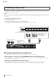
Connections Connecting the PA2120 Power Amplifier When using a large number of speakers that the MA2120 is not capable of handling alone, it is possible to connect a PA2120 power amplifier to provide extra capacity. To utilize this functionality, connect the [LINE OUT] jack of the MA2120 to the [INPUT] jack of the PA2120 using an RCA cable when all devices are powered off. If you wish to further expand capacity, it is possible to connect another PA2120 power amplifier.
Connections Connecting a Control Panel Connecting Yamaha Digital Control Panel (DCP1V4S, DCP4S, DCP4V4S) to MA2120 enables you to control the volume, to switch inputs, etc. remotely. You can connect up to two control panels. The total length of the cables from the MA2120 to the last control panel must not exceed 800 meters in the case of 24AWG. NOTE When connecting control panels via DCH8, the total length of the cables to the final control panel must be less than 200m (according to DCH8 specifications).
Connections Using the [REMOTE] Connector (Euroblock 3-pin) You can connect switches to the rear panel [REMOTE] connector, and use them to remotely mute/unmute outputs of all channels, or switch the power standby/on status. From the left, the [REMOTE] connector consists of M (mute all), S (standby), and G (ground) pins. The [REMOTE] connector uses a Euroblock plug. For details on how to connect Euroblock plugs, refer to “Attaching Euroblock Plugs.
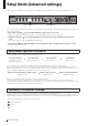
Setup Mode (Advanced settings) Advanced settings for MA2120 power amplifier can be configured by using the [SETUP] encoder and input level knobs 1 - 8. Input level knobs 1 - 8 [SETUP] encoder There are three types of setup modes that can be used to configure advanced settings. Operation and functionality for each setup mode type is shown as follows: • Input channel setup mode Press and hold the [SETUP] encoder for at least one second.
Setup Mode (Advanced settings) Operation Procedure Turning Off the Microphone Input High-Pass Filter The microphone input high-pass filter (Cut-off frequency: 120Hz) is turned on by default. This can reduce wind or popping noise when using a microphone. The high-pass filter is enabled for the input channel when the [GAIN] switch is set to either “MIC(+24V)” or “MIC”.
Setup Mode (Advanced settings) Applying EQ (equalizer) to the Input Signal A two-band EQ (TREBLE and BASS) can be applied to the input signal to adjust the sound quality. The EQ range is ±10dB and can be set in intervals of 1dB. 2 3 1, 4, 5 1 Press and hold the [SETUP] encoder for at least one second. 2 Press input level knob 3 (BASS), or input level knob 4 (TREBLE). 3 Press input level knobs 1 - 8 to select to which input channel you would like to apply the EQ.
Setup Mode (Advanced settings) Applying Echo/Reverb to the Input Signal Echo/Reverb can be applied to the INPUT 1 and INPUT 3 input signals to add extra sound reverberation. The “Echo” type, which allows for the adjustment of reverberation time, or three “Reverb” types are available. 3 2 1 Press and hold the [SETUP] encoder for at least one second. 2 3 Press input level knob 5. 4 Turn the [SETUP] encoder to select the echo/ reverb preset.
Setup Mode (Advanced settings) Adjusting the Ducker Sensitivity You can adjust the sensitivity of the ducker function. When there is an input signal to [INPUT 1] or [INPUT 3], this function can mute the microphone input for channels outside that particular output zone, or lower their line input volume by 24dB. The ducker input sensitivity can be set to “Low”, “Mid”, or “High”.
Setup Mode (Advanced settings) Setting the Chime Volume You can set the volume of the chime that is emitted when the microphone input is turned on or off via by the control panel switch. The volume can be set to “Mute”, “-12dB”, or “-6dB”. You can set different volumes for each zone. 1, 2 3 1, 4, 5 1 Press and hold the [SETUP] encoder and input level knob 1 simultaneously for at least one second. 2 3 Press input level knob 1. 4 Turn the [SETUP] encoder to set the volume.
Setup Mode (Advanced settings) Microphone Feedback Suppressor You can turn the feedback suppressor function on or off. This function automatically suppresses microphone feedback when detected. The feedback suppressor is enabled for the input channel when the [GAIN] switch is set to either “MIC(+24V)” or “MIC”. NOTE The feedback suppressor is applied to the [MONO SUM INPUT] when the [GAIN] switch for INPUT 5 and 6 is set to either “MIC(+24V)” or “MIC”.
Setup Mode (Advanced settings) List of DIP Switch Settings DIP switch functions are also listed in the “Controls and Functions” section of the owner's manual. Only operate DIP switches when the device is powered off or in standby mode. The setting change will be applied after carrying out a power cycle by pressing the [z] button on the front panel. [SETUP] DIP switches DIP switch 1/2: Panel lock Set knobs and controls to be locked on the panel.
Setup Mode (Advanced settings) DIP switches 7/8: Ducker Configure the settings for the Ducker function. This can mute the microphone input of other channels, and lower the volume of line input when signals are input to [INPUT 1] or [INPUT 3]. 7 8 Setting Ducker off Ducker on when signals are input to [INPUT 1]. Ducker on when signals are input to [INPUT 3]. Ducker on when signals are input to [INPUT 1] or [INPUT 3]. If signals are input to both of them, [INPUT 1] is given precedence.
Appendix List of Functions Operated Via the Control Panel DCP1V4S Panel ID Encoder 0, 1 Volume control 2, 3 Volume control [INPUT 1] on/off Chime on 4, 5 Volume control 6, 7 Switch 1 Switch 2 Switch 3 Switch 4 Encoder operation target: SPEAKERS A Encoder operation target: SPEAKERS B [INPUT 3] on/off Chime on Encoder operation target: SPEAKERS A Encoder operation target: SPEAKERS B [INPUT 1] on/off Chime on Mute [INPUT] 7 and 8 [INPUT 3] on/off Chime on Mute [INPUT] 7 and 8 Encoder opera
Appendix High-Impedance and Low-Impedance Connections For a high-impedance connection, a speaker transformer that raises the impedance to several hundred or thousand ohms is added to the speaker system. This allows the speaker system to be effectively driven with much lower current than is required for a low-impedance connection. Therefore, a large number of speaker systems can be connected.
Technical Specifications Specification Outputs (SPEAKER OUT) Output Power 20msec Burst (THD+N=1%) AMP MODE = 3Ω 100W x 2ch AMP MODE = 4Ω 120W x 2ch AMP MODE = 8Ω 100W x 2ch AMP MODE = 70V/120W 120W x 2ch AMP MODE = 100V/120W 120W x 2ch AMP MODE = 70V/200W 200W x 1ch AMP MODE = 100V/200W Terminal 200W x 1ch 7.
Technical Specifications Electrical Characteristics Class D Amplifier type (Output circuitry) THD+N Frequency Response LINE IN to SPEAKER OUT, Half power@1kHz AMP MODE = 3Ω, 4Ω, 8Ω ≤ 0.2% LINE IN to SPEAKER OUT, Half power@1kHz AMP MODE = 70V, 100V/120W ≤ 0.2% LINE IN to SPEAKER OUT, Half power@1kHz AMP MODE = 70V, 100V/200W ≤ 0.2% LINE IN to SPEAKER OUT, 50Hz to 20kHz@1W AMP MODE = 3Ω, 4Ω, 8Ω 0dB, -3.0dB, +1.0dB LINE IN to SPEAKER OUT, 90Hz to 20kHz@1W AMP MODE = 70V, 100V/120W 0dB, -3.
Technical Specifications Power Consumption Standby, default setting AMP MODE = All ≤ 1W Idle AMP MODE = 3Ω, 4Ω, 8Ω 15W Idle AMP MODE = 70V, 100V 20W 1/8 Output, Pink noise AMP MODE = 4Ω 60W 1/8 Output, Pink noise AMP MODE = 70V/120W 60W ENERGY STAR • It automatically enters into standby mode when no input signal is detected for 25 minutes in order to save power while not in use. • Amplifier efficiency: 44% and more. • Less than 1W in standby.
Technical Specifications Dimensions (unit: mm) 379.4 361.8 430 166 MA2120 Setup Guide 45.
L/R R L R L 㻳 㻙 㻗 㻳 㻙 㻗 REMOTE DCP INPUT 8 INPUT 7 INPUT 6 INPUT 5 INPUT 4 INPUT 3 INPUT 2 INPUT 1 㻳 㻙 㻗 㻳 㻙 㻗 㻳 㻙 㻗 㻳 㻙 㻗 STANDBY LOGIC R L 㻗 HA 㻙 㻗 HA 㻙 㻗 HA 㻙 㻗 HA 㻙 PHANTOM +24V LINE LINE MIC LINE MIC PHANTOM +24V 㻗 HA 㻙 MIC PHANTOM +24V 㻗 HA 㻙 STEREO SUM STEREO BA SUM SUM INPUT VOLUME INPUT VOLUME INPUT VOLUME INPUT VOLUME INPUT VOLUME INPUT VOLUME INPUT VOLUME INPUT VOLUME ADC ADC ADC ADC ADC ADC ADC ADC CH8 SIGNAL/PEAK CH7 SI
168 MA2120 Setup Guide G%X G%X G%X G%X G%X G%X G%X G%X 6WHUHR PLQL 5&$ 6WHUHR 5&$ 0RQR [ 㻳 (XUR 0,& G%X (XUR 0,& G%X (XUR /,1( G%X (XUR /,1( G%X (XUR 0,& G%X (XUR /,1( G%X ^1RPL G%9 G%X` ,1387 ^1RPL G%9 G%X` ,1387 ^1RPL G%9 G%X` ^1RPL G%X` ,1387 㻗 㻙 㻴㻭 1RUPDO 3KDVH 㻴㻭 0,& /,1( 㻙 㻗 6HQVLWLYLW\ OHYHO 1RPLQDO OHYHO 5&$ 6WHUHR PLQL G%9 G%X 1RQ FOLS OHYHO 1RUPDO 3KDVH *DLQ
Technical Specifications Current Draw 1/8 power is typical of program material with occasional clipping. Refer to these figures for most applications. 1/3 power represents program material with extremely heavy clipping Test signal: Pink Noise, bandwidth limited from 22Hz to 22kHz 1W = 0.860kcal/h, 1BTU = 0.
Yamaha Pro Audio global website http://www.yamahaproaudio.com/ Yamaha Downloads http://download.yamaha.com/ 䳻傢૾҆ಞ丩ଃδѣളεᣋ䍺ᴿ䲆ޢਮ р⎭ᐸ䶏ᆿ॰᯦䰮䐥 ਭӇૂཝড় ᾲ ᇘᡭᵃࣗ✣㓵φ ޢਮ㖇൶φKWWS ZZZ \DPDKD FRP FQ স 䳻傢૾⭫ᆆδ㤅ᐔεᴿ䲆ޢਮ স൶ ⊕㤅ⴷ㤅ᐔᐸ㤅ᐔ᯦॰咵ኧ䐥 ਭ Manual Development Department © 2016 Yamaha Corporation Published 02/2016 ਇ㺂 KSHD-A0 Printed in China ZT16370