
User Manual
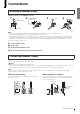

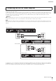
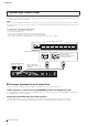
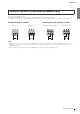
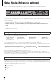
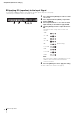
Table Of Contents
- Contents
- Connections
- Setup Mode (Advanced settings)
- Setup Mode Operation Procedure
- Indication of Parameter Settings
- Operation Procedure
- Turning Off the Microphone Input High-Pass Filter
- Applying Compressor to the Microphone Input
- Applying EQ (equalizer) to the Input Signal
- Applying Echo/Reverb to the Input Signal
- Adjusting the Reverb Mix Level
- Adjusting the Ducker Sensitivity
- Regulating BGM Volume (Leveler)
- Setting the Chime Volume
- Adjusting the Line Out Volume by Using the [VOLUME] Knob
- Microphone Feedback Suppressor
- Initializing the settings via connected controll panels (DCP Setup)
- List of DIP Switch Settings
- Appendix
- Technical Specifications

Connections
7
MA2120 Setup Guide
You can connect switches to the rear panel [REMOTE] connector, and use them to remotely mute/unmute outputs of all channels, or
switch the power standby/on status.
From the left, the [REMOTE] connector consists of M (mute all), S (standby), and G (ground) pins.
The [REMOTE] connector uses a Euroblock plug. For details on how to connect Euroblock plugs, refer to “Attaching Euroblock Plugs.”
Muting/unmuting all channels Switching the power standby/on status
NOTE
• When the device is put into standby mode via the [REMOTE] connector, it is not possible to turn the power back on by pressing the
[z] button on the front panel, or by the auto-wake function with input signal detection. The power can only be turned on via the
[REMOTE] connector.
• When the device is put into mute mode via the [REMOTE] connector, the [z] button will flash in green.
Using the [REMOTE] Connector (Euroblock 3-pin)
Turning mute on Turning mute off
Switching the power to standby Turning the power on