
User Manual
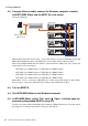
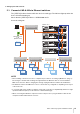
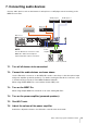
Table Of Contents
- Contents
- Introduction
- 1. Trial setup
- 2. Setting up the wireless access point (DHCP server)
- 3. Setting up MLA-200s
- 4. Setting up MRX7-Ds
- 5. Setting up the audio network
- 6. Setting up ML Touch
- 7. Connecting audio devices
- 8. Operation check
- 9. Installing onto an instrument
- 10. Final operation check
- 11. Troubleshooting

Music Laboratory System Installation Guide 15
5. Setting up the audio network
5-1. Connect all MLA-200s to Ethernet switches.
The [STATUS] indicator flashes while the device is starting up. The indicator lights up when the
device is finished starting up.
Check that the [STATUS] indicator of all MLA-200s are lit.
Connection diagram
NOTE
• Before making connections, be sure to complete the procedure in “3. Setting up MLA-200s” (Page 7).
The changes to the DIP switch settings are applied when the Ethernet cable is connected and the
MLA-200 is turned on. Before changing the settings, unplug the Ethernet cable from the MLA-200.
• The Ethernet switches and MLA-200s can be connected in any configuration, depending on the layout
of the classroom.
• In a system with a large number of students, it may take some time for all [STATUS] indicators to light
up after the MLA-200 (ID=1) for the instructor is finished starting up.
• When connecting the Windows computer used for setup, be sure to plug an Ethernet cable into the
computer’s built-in RJ45 network connector.
Computer
Wireless access
point
(DHCP server)
PoE powered
Ethernet switch
MLA-200
ID=1
(Instructor)
MLA-200
ID=2
(Student 1)
MLA-200
ID=3
(Student 2)
MLA-200
ID=4
(Student 3)
MLA-200
ID=10
(Student 9)
MLA-200
ID=11
(Student 10)
MLA-200
ID=12
(Student 11)
MLA-200
ID=xx
(Student xx)
MLA-200
ID=yy
(Student yy)
MLA-200
ID=zz
(Student zz)
MLA-200
ID=89
(Student 88)
MLA-200
ID=90
(Student 89)
MLA-200
ID=91
(Student 90)
PoE powered
Ethernet switch
PoE powered
Ethernet switch
PoE powered
Ethernet switch
PoE powered
Ethernet switch
MRX7-D ID=1
MRX7-D ID=2
MRX7-D ID=3
MRX7-D ID=4