English Français Owner’s manual Bedienungsanleitung Mode d’emploi Deutsch mLAN AUDIO/MIDI PROCESSOR
mLAN8P-(E).book Page 2 Wednesday, October 11, 2000 11:03 AM SPECIAL MESSAGE SECTION This product utilizes batteries or an external power supply (adapter). DO NOT connect this product to any power supply or adapter other than one described in the manual, on the name plate, or specifically recommended by Yamaha. WARNING: Do not place this product in a position where anyone could walk on, trip over ,or roll anything over power or connecting cords of any kind.
mLAN8P-(E).book Page 3 Wednesday, October 11, 2000 11:03 AM PRECAUTIONS PLEASE READ CAREFULLY BEFORE PROCEEDING WARNING Always follow the basic precautions listed below to avoid the possibility of serious injury or even death from electrical shock, short-circuiting, damages, fire or other hazards. These precautions include, but are not limited to, the following: • Do not open the instrument or attempt to disassemble the internal parts or modify them in any way.
mLAN8P-(E).book Page 4 Wednesday, October 11, 2000 11:03 AM English Introduction Thank you for purchasing the Yamaha mLAN8P. The mLAN8P is an interface unit that supports “mLAN,” a digital network for music which employs a high-performance serial bus “IEEE1394.” The mLAN8P enables you to configure audio and MIDI signal networks easily now without repeatedly re-making complicated connections.
mLAN8P-(E).book Page 5 Wednesday, October 11, 2000 11:03 AM Table of Contents Introduction ................................................................................... 4 Package Contents........................................................................... 4 Names and Functions..................................................................... 8 Connections.................................................................................. 12 Turning the Power On/Off............................
mLAN8P-(E).book Page 6 Wednesday, October 11, 2000 11:03 AM Features English ■ Fast data transfer via mLAN “mLAN” is a digital network designed for music applications. It uses and extends the industry standard “IEEE1394” high performance serial bus. You can now configure more advanced systems much more easily. Please refer to the separate “mLAN Guide Book” for more information on mLAN.
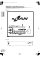
Features ■ Basic concept of mLAN8P digital audio device mLAN8P MIDI OUT MIDI IN MIDI IN DIGITAL IN MIDI OUT DIGITAL OUT ANALOG OUT DIGITAL OUT DIGITAL IN ANALOG IN mLAN device computer* IEEE1394 jack IEEE1394 jack Macintosh computer that supports FireWire English MIDI device IEEE1394 jack IEEE1394 jack mLAN device IEEE1394 jack IEEE1394 jack MIDI signal analog audio signal digital audio signal The diagram shown above illustrates the signal flow through each device connected via the mLAN8P.
mLAN8P-(E).
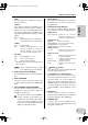
mLAN8P-(E).book Page 9 Wednesday, October 11, 2000 11:03 AM Names and Functions E Mode buttons The LED lights up to indicate the status of the unit as follows: These buttons, combined with the channel/ function buttons, are used to select the setting parameters. [LOCK] The condition in which the mLAN8P receives word clock from another device correctly is called “lock.” The left LOCK LED indicates the status of signals input at Digital In. The right LOCK LED indicates the status of mLAN signals.
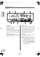
mLAN8P-(E).book Page 10 Wednesday, October 11, 2000 11:03 AM Names and Functions Rear Panel English A B CONTRAST C ANALOG OUT-B OUT2/R DC IN OUT1/L COAXIAL OUT IN IN2/R D SERIAL I/O MIDI OUT-A IN IN1/L mLAN OPTICAL OUT IN 3 IEEE1394 S200 2 1 RT/ERR ACTIVE E F G A CONTRAST This knob is used to adjust the contrast of the LCD on the top panel. B ANALOG IN/OUT jacks These jacks are used to input and output analog audio signals.
mLAN8P-(E).book Page 11 Wednesday, October 11, 2000 11:03 AM Names and Functions These jacks are used to input and output digital audio signals via digital audio pin cables. NOTE Select either the COAXIAL IN jacks or OPTICAL IN jacks. (page 33.) These jacks, along with the OPTICAL IN/OUT jacks 7 are also called “DIGITAL IN/OUT.” G OPTICAL IN/OUT jacks I RT/ERR LED This LED indicates the following statuses. green : The mLAN8P is a “root.” orange : An error has occurred.
mLAN8P-(E).book Page 12 Wednesday, October 11, 2000 11:03 AM Connections English This section explains how to connect mLAN and MIDI devices (such as tone generators and keyboards) to a personal computer via the mLAN8P. (1) Connecting the power supply adaptor Connect the plug of the included power supply adaptor (PA-5C) to the DC IN jack on the rear panel of the mLAN8P, and connect the adaptor part to an AC outlet.
mLAN8P-(E).book Page 13 Wednesday, October 11, 2000 11:03 AM Connections (3) Connecting an mLAN (IEEE1394) device mLAN8P ANALOG OUT-B OUT2/R IN OUT1/L IN2/R COAXIAL OUT IN English Use an IEEE1394 standard (6-pin) cable to connect the mLAN (IEEE1394) jack on the mLAN (IEEE1394) device to the mLAN (IEEE1394) jack on the mLAN8P. At this time, you do not have to turn off the power to either device.
mLAN8P-(E).book Page 14 Wednesday, October 11, 2000 11:03 AM Connections (5) Connecting analog audio devices (amplifier, speakers, mixer, etc.) Connect ANALOG OUT 1/L and 2/R to two channels on the mixer.
mLAN8P-(E).book Page 15 Wednesday, October 11, 2000 11:03 AM Connections (7) Connecting a pair of headphones PHONES English Connect a pair of headphones to the PHONES jacks on the front panel of the mLAN8P to monitor the signal output at ANALOG OUT 1/L and 2/R (Stereo Mix).
mLAN8P-(E).book Page 16 Wednesday, October 11, 2000 11:03 AM English Internal Configuration of the mLAN8P mLAN jacks1-3 MIDI IN mLAN MIDI OUT mLAN MIDI IN mLAN audio input*3 mLAN audio output COAXIAL IN OPTICAL IN (Digital In*2) L Audio/ mLAN audio direct conversion MIDI/ mLAN MIDI conversion Audio device Digital audio device mLAN device (e.g.
mLAN8P-(E).book Page 17 Wednesday, October 11, 2000 11:03 AM mLAN plugs mLAN output plugs (Indicated in the “From” field in mLAN Patchbay.) mLAN audio mLAN input plugs (Indicated in the “To” field in mLAN Patchbay.
mLAN8P-(E).book Page 18 Wednesday, October 11, 2000 11:03 AM Function Trees ■ Mixer input section (mLAN Audio 1-8 Ch) English Mode button [MIXER 1] Channel button [1]-[8] Page button to navigate Input Device/Nickname Audio In Plug Link Gain AUX1 AUX2 Ch (Channel On/Off) Pan (Balance) Level [+1/ENTER] [–1/EXIT] button and [VALUE] dial to set Selects the input source (mLAN audio output plug). Assigns the same value for each pair (1&2, 3&4... 11&12). Adjusts the input level. Adjusts the AUX 1 send level.
mLAN8P-(E).
mLAN8P-(E).book Page 20 Wednesday, October 11, 2000 11:03 AM English Routing I/O signals between mLAN devices After connecting the mLAN8P to each device via cables, you can easily route and connect I/O signals between the devices without re-patching the cables. An operation common to both input and output connections is performed.
mLAN8P-(E).book Page 21 Wednesday, October 11, 2000 11:03 AM Connecting I/O signals between mLAN devices Output to other mLAN devices • AUX1 (A1), AUX2 (A2), Mix Out L (L), Mix Out R (R)...[MIXER2] • Digital In L, Digital In R, A/D In L, A/D In R, MIDI In...[MIDI/UTILITY] English Input to the mLAN8P • Input1–8...[MIXER1] • Input9–12...[MIXER2] • MIDI Out A/B...[MIDI/UTILITY] 2. To set the signal input at the mLAN8P’s channel 1 (Input 1), press channel button [1]. NOTE 3.
mLAN8P-(E).book Page 22 Wednesday, October 11, 2000 11:03 AM Connecting I/O signals between mLAN devices English 4-1. In the “From:” field, use the [+1/ENTER] and [–1/EXIT] buttons or the [VALUE] dial to select the desired device to connect to Channel 1 on the mLAN8P. The Device/Nickname of the selected device flashes. NOTE If you are setting the output destination, the “To:” field appears instead of the “From:” field. 4-2.
mLAN8P-(E).book Page 23 Wednesday, October 11, 2000 11:03 AM Connecting I/O signals between mLAN devices NOTE To cancel the changes, press [EXIT]. NOTE If the UTILITY Confirmation is set to “Off,” a confirmation screen will not appear. Instead, the mLAN plug name flashes a few times, then the mLAN8P automatically executes the connection changes. English 7. The mLAN plug name flashes a few times, then the mLAN8P displays a confirmation screen for the connection changes.
mLAN8P-(E).book Page 24 Wednesday, October 11, 2000 11:03 AM English Mode Functions Settings for the Mixer Input Section: [Mixer 1/2] [1] - [12] This section explains how to route mLAN audio input signals from connected devices to the mLAN8P and how to set the Mixer function parameters. Assign any of eight channel signals from the connected devices to channels [1] - [8], Digital In signals to channels [9] and [10], and A/D In signals to channels [11] and [12].
mLAN8P-(E).book Page 25 Wednesday, October 11, 2000 11:03 AM [Audio In Plug] Select an input “Plug” for connection from the mLAN Plugs (virtual plugs) on the selected device. If the device does not have an appropriate mLAN Plug, “No Source (Destination) Plug” appears. This screen does not appear for [Mixer 2] channels [9] - [12] (Digital In, A/D In). A5000’s “Assignable 1” is connected. English Mode Functions No appropriate Plug was found.
mLAN8P-(E).book Page 26 Wednesday, October 11, 2000 11:03 AM Mode Functions [Aux 1/2] This parameter enables you to set the volume level of the input audio signal that is sent to AUX 1 and 2. The signal sent to AUX 1 and 2 can be assigned to any channel on the mLAN. English Value: – ∞ dB (minimum send level) - +6 dB (maximum send level) [Ch (Channel On/Off)] This parameter turns channels On and Off. With the Off setting, the corresponding channels will be muted.
mLAN8P-(E).book Page 27 Wednesday, October 11, 2000 11:03 AM Mode Functions You can assign the AUX 1/2 signals (routed in the Mixer Input section) to any mLAN channel. 1. Press the [Mixer 2] button. 2. Press the [AUX 1] or [AUX 2] button. 3. Use the [ PAGE ] button to select a parameter you wish to set. 4. Use the [+1/ENTER] and [–1/EXIT] buttons or the [VALUE] dial to select the names of the devices and parameter values.
mLAN8P-(E).book Page 28 Tuesday, June 26, 2001 5:39 PM Mode Functions [Level] This parameter enables you to set the volume level of the AUX signal sent to the output. English Value: 0dB - – ∞ dB Settings for the Mixer Output Section: [Mixer 2] [L] [R] You can assign audio input signals (routed in the Mixer Input section) to any mLAN channel. 1. Press the [Mixer 2] button. 2. Press the [L] or [R] button. 3. Use the [ PAGE ] button to select a parameter you wish to set. 4.
mLAN8P-(E).book Page 29 Wednesday, October 11, 2000 11:03 AM [Balance (Output Balance)] This parameter enables you to set the stereo balance of the stereo audio output signal. The default value is 0 (Center). When you raise the L value, the stereo position shifts to left. When you raise the R value, the stereo position shifts to right. The setting for one channel will also be applied to the other channel.
mLAN8P-(E).book Page 30 Wednesday, October 11, 2000 11:03 AM Mode Functions [MIDI In Plug] Select a “Plug” (that sends out the MIDI signal) from the mLAN Plugs (virtual plugs) on the selected device. If the device does not have an appropriate mLAN Plug, “No Source (Destina- English tion) Plug” appears. NOTE You can select multiple destinations.
mLAN8P-(E).book Page 31 Wednesday, October 11, 2000 11:03 AM Mode Functions The Utility section enables you to set various parameters for the Digital In/Out, A/D In and D/A Out connections, word clock, and system. A [MIDI/UTILITY] - [DIRECT] Follow the steps below to route signals from Digital In and A/D In directly to any mLAN channel, while bypassing the Mixer section. 1. Press the [MIDI/UTILITY] button. 2. Press the [DIRECT] button. 3. Use the [ PAGE ] button to select a parameter you wish to set. 4.
mLAN8P-(E).book Page 32 Wednesday, October 11, 2000 11:03 AM English Mode Functions [Wordclock Source] This parameter is used to select the method of setting the mLAN8P’s word clock. If you have selected “Manual,” use the [Device/Nickname] parameter to specify the name of the device (on the mLAN) that you wish to assign as the word clock master. Value: Internal 44k, Internal 48k, External Coaxial/Oprical, Auto, Group 1 Master, Manual When the internal clock (44.
mLAN8P-(E).book Page 33 Wednesday, October 11, 2000 11:03 AM Mode Functions Follow the steps below to make system-related settings. 1. Press the [MIDI/UTILITY] button. 2. Press the [SYS] button. 3. Use the [ PAGE ] button to select a parameter you wish to set. 4. Use the [+1/ENTER] and [–1/EXIT] buttons or the [VALUE] dial to select the names of the devices and parameter values.
mLAN8P-(E).book Page 34 Wednesday, October 11, 2000 11:03 AM Mode Functions [Set Nickname] [Select Device/Nickname] English Press the [+1/ENTER] button in the [Set Nickname] screen to display this parameter. Select the Device/Nickname of the device on the mLAN whose [Nickname] you wish to change. Use the [+1/ENTER], [–1/EXIT] buttons or the [VALUE] dial to select the Device/Nickname of the device you wish to change. The Device/Nickname will flash. Press the [PAGE ] button to display the following screen.
mLAN8P-(E).book Page 35 Wednesday, October 11, 2000 11:03 AM Mode Functions Press the [+1/ENTER] button to display the screen to confirm the setting. Press the [+1/ENTER] button again to specify the mLAN8P as the root. Press the [–1/EXIT] button to exit the screen without making any changes. English [mLAN8P Set Root] This parameter is used to assign the mLAN8P as the root of the mLAN. [Net Traffic] This screen indicates the amount of data being handled on the mLAN by a percentage and a graph.
mLAN8P-(E).book Page 36 Wednesday, October 11, 2000 11:03 AM Mode Functions English D [MIDI/UTILITY] - [METER] Follow the steps below to display the level meters. The “C” mark appears when the signal clips. 1. Press the [MIDI/UTILITY] button. 2. Press the [METER] button. 3. Use the [ PAGE ] button to select the level meter group you wish to view (All Ch, Input, Output, MIDI). 4. Use the [+1/ENTER] and [–1/EXIT] buttons or the [VALUE] dial to select the channel to view.
mLAN8P-(E).book Page 37 Wednesday, October 11, 2000 11:03 AM LED/LCD Messages LED messages Function Status Indicates the “lock” status of the signal input at Digital In. Indicates the “lock” status of the mLAN signal. LOCK (left) LOCK (right) Green ... Lock, Off ... Unlock Green ... Lock, Off ... Unlock Reports interruption of the sound English Top panel LED due to connection or removal of the Red ... Sound is interrupted. device on the bus, changes to the connection, out of word clock sync, etc.
mLAN8P-(E).book Page 38 Wednesday, October 11, 2000 11:03 AM Specifications English mLAN : IEEE1394 High Performance Serial Bus Data Rate S200, Isochronous Resource Manager capable, Bus Manager capable, Connection Manager Conforms to IEC61883-6 Audio and Music Protocol Digital Audio 8in/8out, MIDI 2in/1out Sampling rate : 44.1kHz, 48kHz : Analog In(A/D Converter) Analog I/O Frequency Response : 5Hz-20KHz(fs=44.1KHz), 5Hz-21KHz(fs=48KHz) Analog Out(D/A Converter) Frequency Response : 5Hz-20KHz(fs=44.
mLAN8P-(E).book Page 39 Wednesday, October 11, 2000 11:03 AM Symbols I +1/ENTER and –1/EXIT buttons .................. 9 PAGE button ............................. 9 IEEE1394 .................................................6, 7 INPUT VOLUME ..........................................9 Internal sampling rate converter .................6 Internal44k ...............................................32 Internal48k ...............................................32 A ACTIVE LED .................................
mLAN8P-(E).book Page 40 Wednesday, October 11, 2000 11:03 AM P PAN/BALANCE ......................................... 26 PHONE VOLUME ....................................... 9 PHONES jack ............................................. 9 English R RS232C jack ............................................. 13 RT/ERR LED .............................................. 11 S SERIAL I/O jack .................................. 10, 13 stereo position ......................................... 26 sync frequency .....
8P-Hyo4.fm Page 42 Wednesday, October 11, 2000 11:10 AM FCC INFORMATION (U.S.A.) 1. IMPORTANT NOTICE: DO NOT MODIFY THIS UNIT! This product, when installed as indicated in the instructions contained in this manual, meets FCC requirements. Modifications not expressly approved by Yamaha may void your authority, granted by the FCC, to use the product. 2. IMPORTANT: When connecting this product to accessories and/ or another product use only high quality shielded cables.
8P-Hyo4.fm Page 43 Wednesday, October 11, 2000 11:10 AM For details of products, please contact your nearest Yamaha or the authorized distributor listed below. Pour plus de détails sur les produits, veuillez-vous adresser à Yamaha ou au distributeur le plus proche de vous figurant dans la liste suivante. NORTH AMERICA CANADA Yamaha Canada Music Ltd. 135 Milner Avenue, Scarborough, Ontario, M1S 3R1, Canada Tel: 416-298-1311 U.S.A. Yamaha Corporation of America 6600 Orangethorpe Ave., Buena Park, Calif.
8P-Hyo4.fm Page 44 Wednesday, December 20, 2000 2:11 PM Yamaha Manual Library (English versions only) http://www2.yamaha.co.jp/manual/english/ This document is printed on recycled chlorine free (ECF) paper with soy ink. Auf Recycling-Umweltpapier gedruckt. Ce document a été imprimé sur du papier recyclé non blanchi au chlore. M.D.G.,Pro Audio & Digital Musical Instrument Division, Yamaha Corporation © 2000 Yamaha Corporation V516510 010APAP2.