
Data List
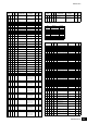
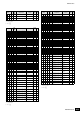
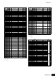
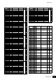
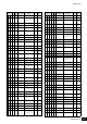
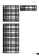

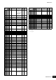
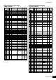
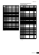
Table Of Contents
MONTAGE Data List
218
MIDI Data Table
TOTAL SIZE = 70 46 (HEX)
p = Part number
0 – F
e = Element number
0 – 7
Address Size
Data
Range
(HEX)
Parameter Name Description
Default
(HEX)
Notes
42 ep 00 1 00 – 15 Filter Type LPF24D, LPF24A,
LPF18, LPF18s,
LPF12+HPF12,
LPF6+HPF12, HPF24D,
HPF12, BPF12D, BPFw,
BPF6, BEF12, BEF6,
DualLPF, DualHPF,
DualBPF, DualBEF,
LPF12+BPF6, Thru
04
01 2 00 – 01
00 – 7F
Filter Cutoff Frequency 0 – 255
1st bit6-0 bit13-7
2nd bit6-0 bit6-0
01 20
03 1 00 – 7F Filter Cutoff Velocity
Sensitivity
-64 – +63 40
04 1 reserved
05 1 00 – 7F Filter Resonance/Width 0 – 127 00 Not available
for LPF6 and
Thru
06 1 00 – 7F Filter Resonance
Velocity Sensitivity
-64 – +63 40
07 2 00 – 01
00 – 7F
HPF Cutoff Frequency 0 – 255
1st bit6-0 bit13-7
2nd bit6-0 bit6-0
00 00
09 1 reserved
0A 2 00 – 01
00 – 7F
Distance -128 – +127
1st bit6-0 bit13-7
2nd bit6-0 bit6-0
01 00 This is
available
when Filter
Typ e i s set to
Dual.
0C 2 00 – 01
00 – 7F
Filter Gain 0 – 255
1st bit6-0 bit13-7
2nd bit6-0 bit6-0
01 66
0E 1 00 – 7F FEG Hold Time 0 – 127 00
0F 1 00 – 7F FEG Attack Time 0 – 127 00
10 1 00 – 7F FEG Decay 1 Time 0 – 127 40
11 1 00 – 7F FEG Decay 2 Time 0 – 127 40
12 1 00 – 7F FEG Release Time 0 – 127 50
13 2 00 – 01
00 – 7F
FEG Hold Level -128 – +127 (-9600 –
+9600 [cent])
1st bit6-0 bit13-7
2nd bit6-0 bit6-0
01 00
15 2 00 – 01
00 – 7F
FEG Attack Level : 01 7F
17 2 00 – 01
00 – 7F
FEG Decay 1 Level : 01 7F
19 2 00 – 01
00 – 7F
FEG Decay 2 Level : 01 7F
1B 2 00 – 01
00 – 7F
FEG Release Level : 01 00
1D 1 00 – 7F FEG Depth -64 – +63 68
1E 1 00 – 04 FEG Time Velocity
Sensitivity Segment
Attack, Atk+Dcy,
Decay, Atk+Rls, All
04
1F 1 00 – 7F FEG Time Velocity
Sensitivity
-64 – +63 40
20 1 00 – 7F FEG Depth Velocity
Sensitivity
-64 – +63 40
21 1 00 – 04 FEG Depth Velocity
Sensitivity Curve
00 – 04 02
22 1 00 – 7F FEG Time Key Follow
Sensitivity
-64 – +63 40
23 1 00 – 7F FEG Time Key Follow
Sensitivity Center Note
C-2 – G8 18
24 1 00 – 7C Filter Cutoff Scaling
B
r
eak Point 1
C -2 – E8 24 BP1 < BP2 <
BP3 < BP4
25 1 01 – 7D Filter Cutoff Scaling
Break Point 2
C#-2 – F8 30 BP1 < BP2 <
BP3 < BP4
26 1 02 – 7E Filter Cutoff Scaling
Break Point 3
D -2 – F#8 3C BP1 < BP2 <
BP3 < BP4
27 1 03 – 7F Filter Cutoff Scaling
Break Point 4
D#-2 – G8 48 BP1 < BP2 <
BP3 < BP4
28 2 00 – 01
00 – 7F
Filter Cutoff Scaling
Offset 1
-128 – +127
1st bit6-0 bit13-7
2nd bit6-0 bit6-0
01 00
2A 2 00 – 01
00 – 7F
Filter Cutoff Scaling
Offset 2
: 01 00
2C 2 00 – 01
00 – 7F
Filter Cutoff Scaling
Offset 3
: 01 00
2E 2 00 – 01
00 – 7F
Filter Cutoff Scaling
Offset 4
: 01 00
30 1 00 – 7F Filter Cutoff Key Follow
Sensitivity
-200% – +200% 4A
31 1 00 – 7F HPF Cutoff Key Follow
Sensitivity
-200% – +200% 40
32 1 00 – 05 EQ Type 2-band, P.EQ, Boost6,
Boost12, Boost18, Thru
00
33 1 00 – 1F EQ Q 0.7 – 10.3 00 This is
available
only when
P. E Q is
selected for
EQ Type.
34 2 00 – 01
00 – 7F
EQ 1 Frequency 50.1 – 2.00k (2 Band)
139.7 – 12.9k (P.EQ)
1st bit6-0 bit13-7
2nd bit6-0 bit6-0
00 36 This is
available
only when
2-band or
P. E Q is
selected for
EQ Type.
36 1 20 – 60 EQ 1 Gain -12.00dB – +12.00dB 40
37 2 01
03 – 71
EQ 2 Frequency 503.8 – 10.1k
1st bit6-0 bit13-7
2nd bit6-0 bit6-0
01 67 This is
available
only when
2-band is
selected for
EQ Type.
39 1 20 – 60 EQ 2 Gain -12.00dB – +12.00dB 40
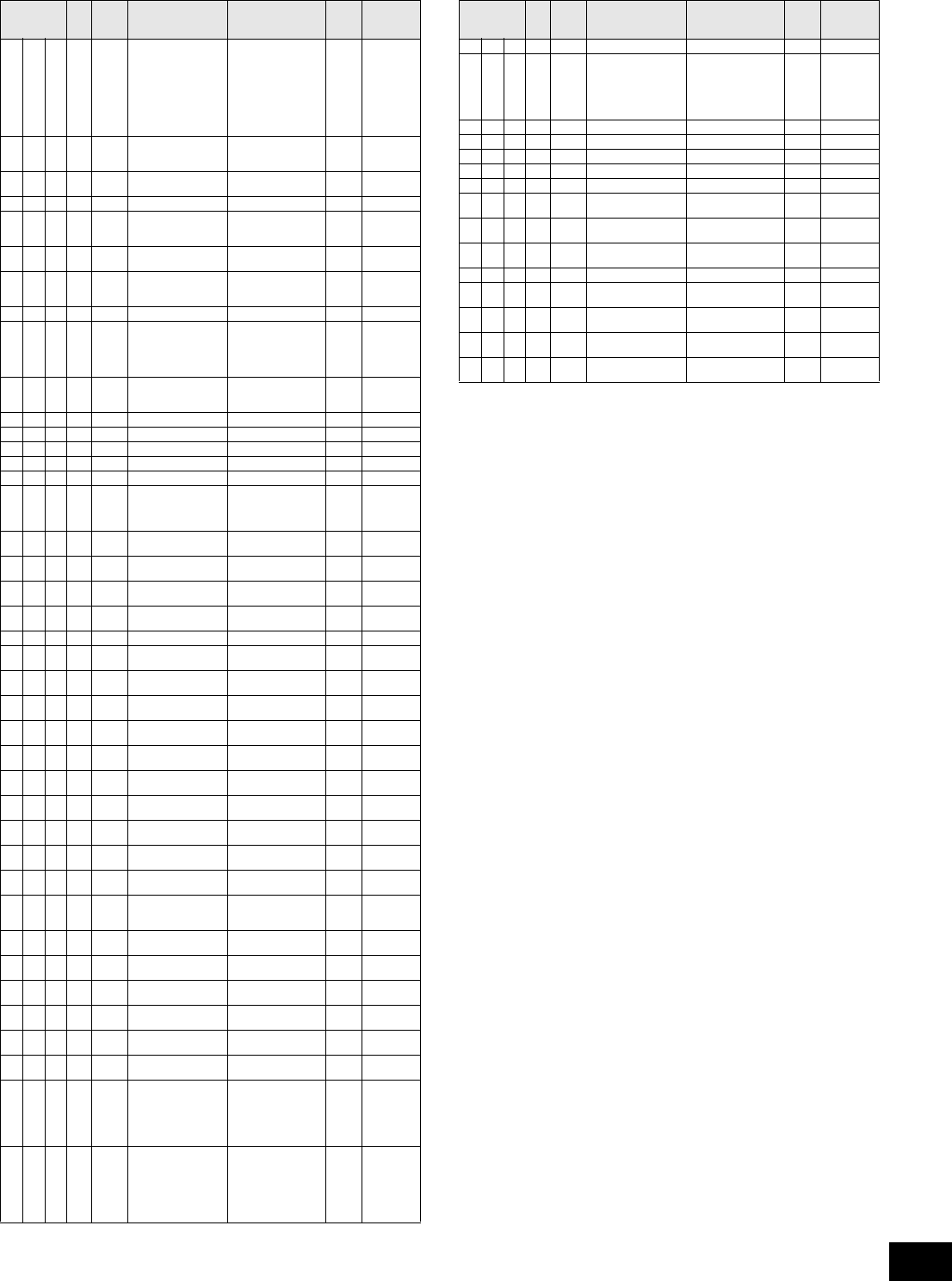
3A 1 00 – 02 LFO Wave Saw, Triangle, Square 01
3B 1 00 – 01 LFO Key On Reset Off, On 01
3C 1 00 – 7F LFO Delay Time 0 – 127 00
3D 1 00 – 3F LFO Speed 0 – 63 26
3E 1 00 – 7F LFO Amplitude
Modulation Depth
0 – 127 00
3F 1 00 – 7F LFO Pitch Modulation
Depth
0 – 127 00
40 1 00 – 7F LFO Filter Modulation
Depth
0 – 127 00
41 1 00 – 7F LFO Fade In Time 0 – 127 00
42 1 00 – 05 Part LFO Phase Offset +0, +90, +120, +180,
+240, +270
00
43 1 00 – 7F Part LFO Destination 1
Depth Ratio
0 – 127 7F
44 1 00 – 7F Part LFO Destination 2
Depth Ratio
0 – 127 7F
45 1 00 – 7F Part LFO Destination 3
Depth Ratio
0 – 127 7F
Address Size
Data
Range
(HEX)
Parameter Name Description
Default
(HEX)
Notes