ENGLISH POWERED SPEAKER MS400 Owner’s Manual Mode d’emploi Bedienungsanleitung Manual del Usuario Thank you for purchasing the Yamaha MS400 powered speaker system. The development of this powered bi-amplifier speaker system is a natural extension of Yamaha’s extensive experience and knowledge of PA devices. The MS400 faithfully reproduces sound for a wide range of applications. Please read this owner’s manual thoroughly to make the best use of the MS400 for the longest possible period of time.
Precautions • Do not allow water to enter this unit or allow the unit to become wet. Fire or electrical shock may result. • Do not place a container with liquid or small metal objects on top of this unit. Liquid or metal objects inside this unit are a fire and electrical shock hazard. • Connect the included power cord only to an AC outlet of the type stated in this Owner’s Manual or as marked on the unit. Failure to do so is a fire and electrical shock hazard.
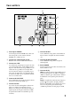
Rear Panel 9 8 LOW HIGH 7 LEVEL LEVEL LEVEL 6 2 1 2 3 1 1 2 A POWER switch This switch turns the power to the MS400 on and off. When you turn this switch on, the POWER indicator (8) lights up green. B AC IN connector Connect the included power cord here. C LINE connectors These balanced connectors accept input from line-level sources, such as a mixer. The connectors include: an XLR-3-31 type; an XLR-3-32 type; a 1/4" TRS phone jack.
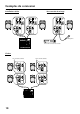
Connection Examples Stereo setup Without a mixer 2 1 2 3 1 1 2 3 3 1 3 2 1 2 1 2 3 3 1 3 2 1 2 1 3 3 2 LINE OUT Microphone CD player or tape deck Mixer Daisy chain To the next speaker 2 1 2 3 2 2 1 2 1 2 2 1 Mixer 1 2 1 3 LINE OUT 4 2 3 3 1 3 3 1 3 2 3 1 1 3 3 1 To the next speaker 2 1 3 3 2
Specifications ■ General specifications Controls LEVEL ............... LINE, MIC, MASTER EQ........................LOW: 0 (Max.) ~ –10 dB (Min.) at 55 Hz HIGH: ±3 dB (HF) Power switch.......................... On/Off Connectors (all balanced): LINE in/out........................XLR-3-31, XLR-3-32, phone (They are all connected in parallel and can be used as line outputs.) MIC in............................ XLR-3-31 POWER indicator................... Green LED Power Requirement USA and Canada .......
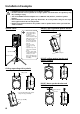
Installation Examples • Installation must be carried out by an installation specialist. • Do not install two or more speakers on a single speaker stand or bracket. The speaker(s) may fall, resulting in injury. • You need a BAD251 bracket adapter to use a BWS251-400, BCS251, or BBS251 speaker bracket. • Due to abrasion or corrosion, parts may deteriorate. To use the product safely, be sure to perform regular maintenance and inspections.
FRANÇAIS Enceinte active MS400 Mode d’emploi Nous vous remercions d’avoir opté pour le système d’enceinte active MS400. La conception de cette enceinte active à double amplificateur est le fruit de la longue expérience et du savoir-faire de Yamaha dans le domaine de la sonorisation. Veuillez lire complètement ce mode d’emploi afin d’exploiter au mieux et le plus longtemps possible votre MS400. Conservez le mode d’emploi dans un endroit sûr pour toute référence ultérieure.
Précautions • Evitez de mouiller l’appareil ou de laisser pénétrer de l’eau dans son boîtier. Il y a risque d’incendie ou d’électrocution. • Ne posez pas de récipient contenant des liquides ou de petits objets métalliques sur l’appareil. Si un liquide ou des objets métalliques pénètrent dans l’appareil, il y a risque d’incendie ou d’électrocution.
Face arrière 9 8 LOW HIGH 7 LEVEL LEVEL LEVEL 6 2 1 2 3 1 1 2 A Interrupteur POWER Cet interrupteur met la MS400 sous et hors tension. Lorsqu’elle est sous tension, la diode POWER (8) s’allume en vert. B Connecteur d’alimentation AC IN Branchez ici le cordon d’alimentation fourni. C Connecteurs LINE Ces connecteurs symétriques acceptent des sources de niveau ligne telles qu’un mélangeur. Vous disposez d’un connecteur de type XLR-3-31, un connecteur de type XLR-3-32 et un jack TRS 1/4".
Exemples de connexion Installation stéréo 2 1 Sans console de mixage 2 3 1 1 2 3 3 1 3 2 1 2 1 2 3 3 1 3 2 1 2 1 3 3 2 LINE OUT Microphone Lecteur CD ou lecteur de cassette Console de mixage Chaîne Vers l’enceinte suivante 2 1 2 3 2 1 2 1 2 2 1 Console de mixage 1 2 1 3 LINE OUT 10 2 3 3 1 3 3 1 3 2 3 1 2 3 3 1 1 Vers l’enceinte suivante 2 1 3 3 2
Fiche technique ■ Caractéristiques générales Type Enceinte active bass reflex à deux voies à double amplificateur (Diviseur de fréquences électronique à double amplificateur) Enceinte Grave: Cône de 38cm Aigu: 5cm Moteur de compression à membrane en titane Bande passante..................... 50Hz~16kHz (–10dB) Niveau de sortie max............. 124,5dB (1m dans l’axe) Angle de diffusion .................. 90˚ (H)/40˚ (V) Dimensions (L x H x P).......... 449 x 683 x 379mm Poids................................
Exemples d’installation • Consultez un spécialiste pour installer les enceintes. • N’installez pas plus d’une enceinte sur un pied ou une fixation. Les enceintes risqueraient de tomber et de blesser quelqu’un. • Vous avez besoin d’un adaptateur BAD251 pour pouvoir utiliser une fixation BWS251-400, BCS251, ou BBS251. • L’usure ou la corrosion peut détériorer certaines pièces. Pour maintenir une sécurité optimale, veillez à contrôler régulièrement l’état des pièces.
DEUTSCH AKTIVBOX MS400 Bedienungsanleitung Vielen Dank, dass Sie sich für das Aktivboxensystem MS400 von Yamaha entschieden haben. Die Entwicklung dieser Doppelverstärker-Box ist die logische Konsequenz von Yamahas Erfahrung in Sachen Beschallungsgeräte. Die MS400 besticht dank ihrer naturgetreuen Wiedergabe und empfiehlt sich daher für eine Vielzahl von Anwendungen. Bitte lesen Sie sich diese Bedienungsanleitung sorgfältig durch, um über Jahre Freude an der MS400 zu haben.
Vorsichtsmaßnahmen • Vermeiden Sie, daß Wasser oder andere Flüssigkeiten in das Geräteinnere gelangen. Dann besteht nämlich Schlag- oder Brandgefahr. • Stellen Sie keine Behälter mit Flüssigkeiten bzw. legen Sie keine kleinen Metallgegenstände auf das Gerät. Wenn diese nämlich in das Geräteinnere gelangen, besteht Brand- oder Schlaggefahr. • Verbinden Sie das beiliegende Netzkabel dieses Gerätes ausschließlich mit einer Netzsteckdose, die den Angaben in dieser Bedienungsanleitung entspricht.
Rückseite 9 8 LOW HIGH 7 LEVEL LEVEL LEVEL 6 2 1 2 3 1 1 2 A POWER-Schalter Hiermit schalten Sie die MS400 ein und aus. Wenn sie eingeschaltet ist, leuchtet die POWER-Diode (8) grün. B AC IN-Buchse Schließen Sie hier das beiliegende Netzkabel an. C LINE-Anschlüsse An diese symmetrischen Buchsen können Signalquellen mit Line-Pegel (z.B. die Ausgänge eines Mischpults) angeschlossen werden. Die Eingänge sind folgendermaßen ausgeführt: XLR-3-31-Buchse, XLR-3-32-Buchse und 1/4" TRS-Klinkenbuchse.
Anschlussbeispiele Stereo-Betrieb Ohne Mischpult 2 1 2 3 1 1 2 3 3 1 3 2 1 2 1 2 3 3 1 2 3 2 1 1 3 3 2 LINE OUT Mikrofon CD-Spieler oder Cassettendeck Mischpult Erweitertes System Zur nächsten Box 2 1 Zur nächsten Box 2 3 3 1 2 2 1 2 1 2 2 1 Mischpult 1 2 1 3 LINE OUT 16 2 3 3 1 3 3 1 3 2 3 1 1 3 2 1 3 3 2
Technische Daten ■ Allgemeine technische Daten Typ Bi-Amp, 2-Wege, Bass-Reflex-Aktivbox (Doppelverst. mit elektronischer Frequenzweiche) Lautsprecher Bass & Mitten: 38cm-Kegel Höhen: 5cm Kompressionstreiber mit Titanmembran Frequenzgang ....................... 50Hz~16kHz (–10dB) Maximaler Ausgangspegel .... 124,5dB (1m, Strahlungsachse) Strahlungswinkel.................... 90˚ (H)/40˚ (V) Abmessungen (B x H x T) ..... 449 x 683 x 379mm Gewicht.................................. 24,2kg Farbe .................
Aufstellungsbeispiele • Überlassen Sie den Einbau, das Fliegen usw. einem kompetenten Fachmann. • Befestigen Sie niemals mehr als eine Box auf einem Stativ bzw. an einer Halterung. Sonst könnten die Boxen nämlich fallen, was zu Verletzungen führen kann. • Für eine BWS251-400, BCS251 oder BBS251 Halterung brauchen Sie einen BAD251-Adapter. • Abnutzung oder Korrosion können die Verlässlichkeit der mechanischen Teile beeinträchtigen.
ESPAÑOL POTENTE ALTAVOZ MS400 Manual del Usuario Gracias por adquirir el sistema de potente altavoz Yamaha MS400. El desarrollo de este sistema de potente altavoz biamplificador es una extensión natural de la ámplia experiencia y conocimiento de Yamaha acerca de los dispositivos PA. El MS400 reproduce sonido fielmente para una ámplia gama de aplicaciones. Lea este manual del usuario para utilizar correctamente el MS400 y obtener el máximo rendimiento durante mucho tiempo.
Precauciones • No permita que entre agua dentro de la unidad, ni que ésta se humedezca. Esto podría resultar en descargas eléctricas. • No coloque recipientes con líquidos no objetos metálicos pequeños sobre la unidad. Si dentro de la unidad entrasen líquidos u objetos metálicos, se podrían producir descargas eléctricas o un incendio. • Conecte el cable de alimentación incluido sólo a una toma de corriente CA del tipo que aparece en este Manual del Usuario o como se marca en la unidad.
Panel Posterior 9 8 LOW HIGH 7 LEVEL LEVEL LEVEL 6 2 1 2 3 1 1 2 A Conmutador POWER Este conmutador activa y desactiva el MS400. Cuando lo conmuta en on, el indicador POWER (8) se ilumina en verde. B Conector AC IN Conecte el cable de alimentación incluido aquí. C Conectores LINE Estos conectores equilibrados aceptan entrada desde fuentes de nivel de línea, como un mezclador. Los conectores incluyen: un tipo XLR-3-31; un tipo XLR-3-32; un jack de teléfono 1/4" TRS.
Ejemplos de Conexión Instalación estéreo 2 1 2 3 1 Sin un mezclador 1 2 3 3 1 3 2 1 2 1 2 3 3 1 3 2 1 2 1 3 3 2 SALIDA DE LÍNEA Micrófono Reproductor de CD o Platina de cintas Mezclador Conexión en Cadena Al siguiente altavoz Al siguiente altavoz 2 1 2 3 3 1 2 2 1 2 1 2 2 1 Mezclador 1 2 1 3 SALIDA DE LÍNEA 22 2 3 3 1 3 3 1 3 2 3 1 1 3 2 1 3 3 2
Especificaciones ■ Especificaciones Generales Controles LEVEL ............... LINE, MIC, MASTER EQ ..................... LOW: 0 (Máx.) ~ –10dB (Min.) a 55Hz HIGH: ±3dB (HF) Conmutador de alimentación. On/Off Conectores (todos equilibrados): LINE in/out: ................... XLR-3-31, XLR-3-32, teléfono (Todos están conectados en paralelo y se pueden utilizar como salidas de línea.) MIC in: .......................... XLR-3-31 Indicador POWER ................. LED verde Potencia necesaria EE.UU. y Canadá.....
Ejemplos de Instalación • Consulte a un especialista para instalar los altavoces. • No instale dos o más altavoces en un soporte de altavoz o la abrazadera. Puede que el/los altavoz(es) se caigan y se estropeen. • Necesita un adaptador de dispositivo BAD251 para utilizar un dispositivo de altavoz BWS251-400, BCS251, o BBS251. • Puede que las partes se deterioren, debido a la corrosión y la abrasión. Para utilizar este producto con seguridad, asegúrese de realizar un mantenimiento regular e inspecciones.