Read this manual carefully before operating this vehicle.
U5YUE5E0.book Page 1 Tuesday, March 17, 2009 9:02 AM EAU26945 Read this manual carefully before operating this vehicle. This manual should stay with this vehicle if it is sold. YAMAHA MOTOR ELECTRONICS CO., LTD. 1450-6, Mori, Mori-machi, Shuchi-gun, Shizuoka-ken, 437-0292 Japan DECLARATION of CONFORMITY We Company: YAMAHA MOTOR ELECTRONICS CO., LTD.
U5YUE5E0.book Page 1 Tuesday, March 17, 2009 9:02 AM INTRODUCTION EAU10102 Welcome to the Yamaha world of motorcycling! As the owner of the MT01S, you are benefiting from Yamaha’s vast experience and newest technology regarding the design and manufacture of high-quality products, which have earned Yamaha a reputation for dependability. Please take the time to read this manual thoroughly, so as to enjoy all advantages of your MT01S.
U5YUE5E0.book Page 1 Tuesday, March 17, 2009 9:02 AM IMPORTANT MANUAL INFORMATION EAU10132 Particularly important information is distinguished in this manual by the following notations: This is the safety alert symbol. It is used to alert you to potential personal injury hazards. Obey all safety messages that follow this symbol to avoid possible injury or death. WARNING NOTICE TIP A WARNING indicates a hazardous situation which, if not avoided, could result in death or serious injury.
U5YUE5E0.book Page 2 Tuesday, March 17, 2009 9:02 AM IMPORTANT MANUAL INFORMATION EAU10200 MT01S OWNER’S MANUAL ©2009 by Yamaha Motor Co., Ltd. 1st edition, March 2009 All rights reserved. Any reprinting or unauthorized use without the written permission of Yamaha Motor Co., Ltd. is expressly prohibited. Printed in Japan.
U5YUE5E0.book Page 1 Tuesday, March 17, 2009 9:02 AM TABLE OF CONTENTS SAFETY INFORMATION ..................1-1 Ignition circuit cut-off system ........ 3-23 DESCRIPTION ..................................2-1 Left view ..........................................2-1 Right view ........................................2-2 Controls and instruments.................2-3 FOR YOUR SAFETY – PRE-OPERATION CHECKS ............. 4-1 INSTRUMENT AND CONTROL FUNCTIONS .......................................
U5YUE5E0.book Page 2 Tuesday, March 17, 2009 9:02 AM TABLE OF CONTENTS Replacing the license plate light bulb ...........................................6-30 Replacing an auxiliary light bulb ...6-31 Supporting the motorcycle ............6-32 Troubleshooting ............................6-33 Troubleshooting chart ...................6-34 MOTORCYCLE CARE AND STORAGE ..........................................7-1 Matte color caution .........................7-1 Care .............................................
U5YUE5E0.book Page 1 Tuesday, March 17, 2009 9:02 AM SAFETY INFORMATION EAU10283 1 Be a Responsible Owner As the vehicle’s owner, you are responsible for the safe and proper operation of your motorcycle. Motorcycles are single-track vehicles. Their safe use and operation are dependent upon the use of proper riding techniques as well as the expertise of the operator. Every operator should know the following requirements before riding this motorcycle.
U5YUE5E0.book Page 2 Tuesday, March 17, 2009 9:02 AM SAFETY INFORMATION ● ● due to excessive speed or undercornering (insufficient lean angle for the speed). • Always obey the speed limit and never travel faster than warranted by road and traffic conditions. • Always signal before turning or changing lanes. Make sure that other motorists can see you. The posture of the operator and passenger is important for proper control.
U5YUE5E0.book Page 3 Tuesday, March 17, 2009 9:02 AM SAFETY INFORMATION ● 1 ● Do not run engine in poorly ventilated or partially enclosed areas such as barns, garages, or carports. Do not run engine outdoors where engine exhaust can be drawn into a building through openings such as windows and doors. Loading Adding accessories or cargo to your motorcycle can adversely affect stability and handling if the weight distribution of the motorcycle is changed.
U5YUE5E0.book Page 4 Tuesday, March 17, 2009 9:02 AM SAFETY INFORMATION Aftermarket Parts, Accessories, and Modifications While you may find aftermarket products similar in design and quality to genuine Yamaha accessories, recognize that some aftermarket accessories or modifications are not suitable because of potential safety hazards to you or others.
U5YUE5E0.book Page 1 Tuesday, March 17, 2009 9:02 AM DESCRIPTION EAU10410 Left view 1 2,3 4 2 12 11 10 9 8 7 65 8. Shock absorber assembly rebound damping force adjusting knob (page 3-19) 9. Engine oil drain bolt (crankcase) (page 6-9) 10.Engine oil drain bolt (oil tank) (page 6-9) 11.Engine oil filter cartridge (page 6-9) 12.Engine oil filler cap (page 6-9) 1. 2. 3. 4. 5.
U5YUE5E0.book Page 2 Tuesday, March 17, 2009 9:02 AM DESCRIPTION EAU10420 Right view 2 1. 2. 3. 4. 5. 6. 7. 8. 9. Battery (page 6-25) 10.Headlight (page 6-27) 11.Brake pedal (page 3-12) 12.
U5YUE5E0.book Page 3 Tuesday, March 17, 2009 9:02 AM DESCRIPTION EAU10430 Controls and instruments 2 1. 2. 3. 4. 5. 6. 7. 8.
U5YUE5E0.book Page 1 Tuesday, March 17, 2009 9:02 AM INSTRUMENT AND CONTROL FUNCTIONS EAU10976 Immobilizer system 1. Code re-registering key (red bow) 2. Standard keys (black bow) This vehicle is equipped with an immobilizer system to help prevent theft by re-registering codes in the standard keys.
U5YUE5E0.book Page 2 Tuesday, March 17, 2009 9:02 AM INSTRUMENT AND CONTROL FUNCTIONS ● Keep other immobilizer system keys away from the main switch as they may cause signal interference. EAU10471 Main switch/steering lock 3 The main switch/steering lock controls the ignition and lighting systems, and is used to lock the steering. TIP Be sure to use the standard key (black bow) for regular use of the vehicle.
U5YUE5E0.book Page 3 Tuesday, March 17, 2009 9:02 AM INSTRUMENT AND CONTROL FUNCTIONS turned to “OFF”, if the temperature of the sensor for the muffler covers exceeds 55 °C (131 °F), the fan will stay on for a maximum of five minutes, and then switch off automatically. 2. Push the key in from the “OFF” position, and then turn it to “LOCK” while still pushing it. 3. Remove the key. EAU10681 LOCK The steering is locked, and all electrical systems are off. The key can be removed.
U5YUE5E0.book Page 4 Tuesday, March 17, 2009 9:02 AM INSTRUMENT AND CONTROL FUNCTIONS EAU11004 Indicator and warning lights EAU11080 High beam indicator light “ ” This indicator light comes on when the high beam of the headlight is switched on. EAU11365 3 1. 2. 3. 4. 5. 6. 7.
U5YUE5E0.book Page 5 Tuesday, March 17, 2009 9:02 AM INSTRUMENT AND CONTROL FUNCTIONS If the indicator light does not come on initially when the key is turned to “ON”, or if the indicator light remains on, have a Yamaha dealer check the electrical circuit. When the key is turned to “OFF” and 30 seconds have passed, the indicator light will start flashing indicating the immobilizer system is enabled.
U5YUE5E0.book Page 6 Tuesday, March 17, 2009 9:02 AM INSTRUMENT AND CONTROL FUNCTIONS Tachometer Clock mode Odometer and tripmeter modes 1. Tachometer 2. Tachometer red zone 1. Clock 1. Odometer/tripmeter/fuel reserve tripmeter 3 The electric tachometer allows the rider to monitor the engine speed and keep it within the ideal power range. When the key is turned to “ON”, the tachometer needle will sweep once across the r/min range and then return to zero r/min in order to test the electrical circuit.
U5YUE5E0.book Page 7 Tuesday, March 17, 2009 9:02 AM INSTRUMENT AND CONTROL FUNCTIONS To reset a tripmeter, select it by pushing the “SELECT” button, and then push the “RESET” button for at least one second. If you do not reset the fuel reserve tripmeter manually, it will reset itself automatically and the display will return to the prior mode after refueling and traveling 5 km (3 mi). Self-diagnosis device The self-diagnosis device also detects problems in the immobilizer system circuits.
U5YUE5E0.book Page 8 Tuesday, March 17, 2009 9:02 AM INSTRUMENT AND CONTROL FUNCTIONS Brightness control mode Item number “1” is displayed. 3 1. Tachometer panel 2. LCD 3. Tachometer needle The brightness can be adjusted for the following: ● the tachometer panel (item number “1”) ● the LCD (item number “2”) ● the tachometer needle (item number “3”) Select the brightness control mode as follows. 1. Turn the key to “OFF”. 2. Push and hold the “SELECT” button. 3.
U5YUE5E0.book Page 9 Tuesday, March 17, 2009 9:02 AM INSTRUMENT AND CONTROL FUNCTIONS EAU12331 Anti-theft alarm (optional) This model can be equipped with an optional anti-theft alarm by a Yamaha dealer. Contact a Yamaha dealer for more information. EAU12348 Handlebar switches Left 3 1. Tachometer needle 2. Item number 3. Brightness level 1. 2. 3. 4. 5. 7. Push the “SELECT” button and the multi-function display will return to the odometer or tripmeter mode.
U5YUE5E0.book Page 10 Tuesday, March 17, 2009 9:02 AM INSTRUMENT AND CONTROL FUNCTIONS position. To cancel the turn signal lights, push the switch in after it has returned to the center position. Right EAU12500 Horn switch “ ” Press this switch to sound the horn. EAU12660 3 1. Engine stop switch “ 2. Start switch “ ” / ” EAU12350 Pass switch “ ” Press this switch to flash the headlight. EAU12400 Dimmer switch “ / ” Set this switch to “ ” for the high beam and to “ ” for the low beam.
U5YUE5E0.book Page 11 Tuesday, March 17, 2009 9:02 AM INSTRUMENT AND CONTROL FUNCTIONS EAU12830 Clutch lever Make sure that the appropriate setting on the adjusting dial is aligned with the arrow mark on the clutch lever. The clutch lever is equipped with a clutch switch, which is part of the ignition circuit cut-off system. (See page 3-23.) EAU12870 Shift pedal 3 1. 2. 3. 4. Clutch lever Arrow mark Clutch lever position adjusting dial Distance between clutch lever and handlebar grip 1.
U5YUE5E0.book Page 12 Tuesday, March 17, 2009 9:02 AM INSTRUMENT AND CONTROL FUNCTIONS EAU33851 Brake lever be sure to set it by aligning a groove on the adjusting knob with the “ ” mark on the brake lever. EAU12941 Brake pedal 3 1. Brake lever 2. Brake lever position adjusting knob 3. Distance between brake lever and handlebar grip 4. “ ” mark 1. Brake pedal The brake pedal is on the right side of the motorcycle. To apply the rear brake, press down on the brake pedal.
U5YUE5E0.book Page 13 Tuesday, March 17, 2009 9:02 AM INSTRUMENT AND CONTROL FUNCTIONS EAU13074 Fuel tank cap EAU13221 TIP The fuel tank cap cannot be closed unless the key is in the lock. In addition, the key cannot be removed if the cap is not properly closed and locked. EWA11091 WARNING Make sure that the fuel tank cap is properly closed after filling fuel. Leaking fuel is a fire hazard. 1. Fuel tank cap lock cover 2. Unlock. Fuel Make sure there is sufficient gasoline in the tank.
U5YUE5E0.book Page 14 Tuesday, March 17, 2009 9:02 AM INSTRUMENT AND CONTROL FUNCTIONS ately. If gasoline spills on your skin, wash with soap and water. If gasoline spills on your clothing, change your clothes. EAU33501 3 1. Fuel tank filler tube 2. Fuel level 3. Wipe up any spilled fuel immediately. NOTICE: Immediately wipe off spilled fuel with a clean, dry, soft cloth, since fuel may deteriorate painted surfaces or plastic parts. [ECA10071] 4. Be sure to securely close the fuel tank cap.
U5YUE5E0.book Page 15 Tuesday, March 17, 2009 9:02 AM INSTRUMENT AND CONTROL FUNCTIONS EAU34072 Fuel tank breather/overflow hose EAU13445 NOTICE This vehicle is equipped with catalytic converters in the exhaust system. Use only unleaded gasoline. The use of leaded gasoline will cause unrepairable damage to the catalytic converter. EWA10862 WARNING 1. Fuel tank breather/overflow hose 2. Cowling Before operating the motorcycle: ● Check the fuel tank breather/overflow hose connection.
U5YUE5E0.book Page 16 Tuesday, March 17, 2009 9:02 AM INSTRUMENT AND CONTROL FUNCTIONS EAU36692 EAU48091 Seat Adjusting the front fork EWA10180 WARNING To remove the seat 1. Insert the key into the seat lock, and then turn it clockwise. Always adjust both fork legs equally, otherwise poor handling and loss of stability may result. This front fork is equipped with spring preload adjusting bolts, rebound damping force adjusting bolts and compression damping force adjusting bolts. 3 1. Seat holder 2.
U5YUE5E0.book Page 17 Tuesday, March 17, 2009 9:02 AM INSTRUMENT AND CONTROL FUNCTIONS cap as shown in illustration “A”, turn the adjusting bolt in direction (b) until the alignment marks match. È 2 (b) É 2 (b) 1 (b) 2 (a) (a) 1 (a) 1 1. Spring preload adjusting bolt 2. Alignment marks To set the standard setting, turn the adjusting bolt 7 complete turns in direction (b), making sure the alignment marks match. 1. Spring preload adjusting bolt 2. Alignment marks b.
U5YUE5E0.book Page 18 Tuesday, March 17, 2009 9:02 AM INSTRUMENT AND CONTROL FUNCTIONS 3 To increase the spring preload and thereby hardening it, turn the adjusting bolt in direction (a) from the standard setting, making sure to turn the bolt complete turns so that the alignment marks match. To decrease the spring preload and thereby softening it, turn the adjusting bolt in direction (b) from the standard setting, making sure to turn the bolt complete turns so that the alignment marks match.
U5YUE5E0.book Page 19 Tuesday, March 17, 2009 9:02 AM INSTRUMENT AND CONTROL FUNCTIONS EAU48080 TIP Although the total number of clicks of a damping force adjusting mechanism may not exactly match the above specifications due to small differences in production, the actual number of clicks always represents the entire adjusting range. To obtain a precise adjustment, it would be advisable to check the number of clicks of each damping force adjusting mechanism and to modify the specifications as necessary.
U5YUE5E0.book Page 20 Tuesday, March 17, 2009 9:02 AM INSTRUMENT AND CONTROL FUNCTIONS (a) 1 (b) 2 3 Spring preload: Minimum (soft): Distance A = 165 mm (6.50 in) Standard: Distance A = 160 mm (6.30 in) Maximum (hard): Distance A = 152 mm (5.98 in) 3. Tighten the locknut to the specified torque. NOTICE: Always tighten the locknut against the adjusting nut, and then tighten the locknut to the specified torque. 1. Special wrench 2. Extension bar [ECA10121] Tightening torque: Locknut: 25 Nm (2.
U5YUE5E0.book Page 21 Tuesday, March 17, 2009 9:02 AM INSTRUMENT AND CONTROL FUNCTIONS EWA10221 (a) (b) 1 1.
U5YUE5E0.book Page 22 Tuesday, March 17, 2009 9:02 AM INSTRUMENT AND CONTROL FUNCTIONS EAU15281 3 EAU15301 EXUP system Sidestand This model is equipped with Yamaha’s EXUP (EXhaust Ultimate Power valve) system. This system boosts engine power by means of a valve that regulates the diameter of the exhaust pipe. The EXUP system valve is constantly adjusted in accordance with the engine speed by a computer-controlled servomotor. The sidestand is located on the left side of the frame.
U5YUE5E0.book Page 23 Tuesday, March 17, 2009 9:02 AM INSTRUMENT AND CONTROL FUNCTIONS EAU44892 Ignition circuit cut-off system The ignition circuit cut-off system (comprising the sidestand switch, clutch switch and neutral switch) has the following functions. ● It prevents starting when the transmission is in gear and the sidestand is up, but the clutch lever is not pulled. ● It prevents starting when the transmission is in gear and the clutch lever is pulled, but the sidestand is still down.
U5YUE5E0.book Page 24 Tuesday, March 17, 2009 9:02 AM INSTRUMENT AND CONTROL FUNCTIONS With the engine turned off: 1. Move the sidestand down. 2. Make sure that the engine stop switch is set to “ 3. Turn the key on. 4. Shift the transmission into the neutral position. 5. Push the start switch. Does the engine start? WARNING If a malfunction is noted, have a Yamaha dealer check the system before riding. ”. 3 YES NO The neutral switch may not be working correctly.
U5YUE5E0.book Page 1 Tuesday, March 17, 2009 9:02 AM FOR YOUR SAFETY – PRE-OPERATION CHECKS EAU15596 Inspect your vehicle each time you use it to make sure the vehicle is in safe operating condition. Always follow the inspection and maintenance procedures and schedules described in the Owner’s Manual. EWA11151 WARNING Failure to inspect or maintain the vehicle properly increases the possibility of an accident or equipment damage. Do not operate the vehicle if you find any problem.
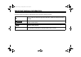
U5YUE5E0.book Page 2 Tuesday, March 17, 2009 9:02 AM FOR YOUR SAFETY – PRE-OPERATION CHECKS ITEM CHECKS PAGE Clutch • Check operation. • If soft or spongy, have Yamaha dealer bleed hydraulic system. • Check hydraulic system for leakage. Throttle grip • Make sure that operation is smooth. • Check cable free play. • If necessary, have Yamaha dealer adjust cable free play and lubricate cable and grip housing. Control cables • Make sure that operation is smooth. • Lubricate if necessary.
U5YUE5E0.book Page 1 Tuesday, March 17, 2009 9:02 AM OPERATION AND IMPORTANT RIDING POINTS EAU15951 EAU46990 EAU36743 Starting the engine Read the Owner’s Manual carefully to become familiar with all controls. If there is a control or function you do not understand, ask your Yamaha dealer. EWA10271 WARNING Failure to familiarize yourself with the controls can lead to loss of control, which could cause an accident or injury.
U5YUE5E0.book Page 2 Tuesday, March 17, 2009 9:02 AM OPERATION AND IMPORTANT RIDING POINTS 5 2. Shift the transmission into the neutral position. (See page 5-2.) The neutral indicator light should come on. If not, ask a Yamaha dealer to check the electrical circuit. 3. Start the engine by pushing the start switch. NOTICE: For maximum engine life, never accelerate hard when the engine is cold! [ECA11041] If the engine fails to start, release the start switch, wait a few seconds, and then try again.
U5YUE5E0.book Page 3 Tuesday, March 17, 2009 9:02 AM OPERATION AND IMPORTANT RIDING POINTS EAU16810 Tips for reducing fuel consumption Fuel consumption depends largely on your riding style. Consider the following tips to reduce fuel consumption: ● Shift up swiftly, and avoid high engine speeds during acceleration. ● Do not rev the engine while shifting down, and avoid high engine speeds with no load on the engine. ● Turn the engine off instead of letting it idle for an extended length of time (e.g.
U5YUE5E0.book Page 4 Tuesday, March 17, 2009 9:02 AM OPERATION AND IMPORTANT RIDING POINTS EAU17213 Parking When parking, stop the engine, and then remove the key from the main switch. EWA10311 WARNING ● 5 ● ● Since the engine and exhaust system can become very hot, park in a place where pedestrians or children are not likely to touch them and be burned. Do not park on a slope or on soft ground, otherwise the vehicle may overturn, increasing the risk of a fuel leak and fire.
U5YUE5E0.book Page 1 Tuesday, March 17, 2009 9:02 AM PERIODIC MAINTENANCE AND ADJUSTMENT EAU17241 EWA15121 Periodic inspection, adjustment, and lubrication will keep your vehicle in the safest and most efficient condition possible. Safety is an obligation of the vehicle owner/operator. The most important points of vehicle inspection, adjustment, and lubrication are explained on the following pages.
U5YUE5E0.book Page 2 Tuesday, March 17, 2009 9:02 AM PERIODIC MAINTENANCE AND ADJUSTMENT EAU46861 TIP ● ● ● The annual checks must be performed every year, except if a kilometer-based maintenance, or for the UK, a mileage-based maintenance, is performed instead. From 50000 km (30000 mi), repeat the maintenance intervals starting from 10000 km (6000 mi). Items marked with an asterisk should be performed by a Yamaha dealer as they require special tools, data and technical skills.
U5YUE5E0.book Page 3 Tuesday, March 17, 2009 9:02 AM PERIODIC MAINTENANCE AND ADJUSTMENT EAU1770C General maintenance and lubrication chart ODOMETER READING NO. ITEM CHECK OR MAINTENANCE JOB 1000 km (600 mi) 10000 km (6000 mi) 20000 km (12000 mi) 30000 km (18000 mi) 40000 km (24000 mi) ANNUAL CHECK √ 1 * Air filter element • Replace. 2 * Clutch • Check operation, fluid level and vehicle for fluid leakage.
U5YUE5E0.book Page 4 Tuesday, March 17, 2009 9:02 AM PERIODIC MAINTENANCE AND ADJUSTMENT ODOMETER READING NO. 10 ITEM Drive chain 11 * Steering bearings 12 * Chassis fasteners CHECK OR MAINTENANCE JOB • Check chain slack, alignment and condition. • Adjust and lubricate chain with a special O-ring chain lubricant thoroughly. • Check bearing play and steering for roughness.
U5YUE5E0.book Page 5 Tuesday, March 17, 2009 9:02 AM PERIODIC MAINTENANCE AND ADJUSTMENT ODOMETER READING NO. ITEM CHECK OR MAINTENANCE JOB 21 * Rear suspension relay arm and connecting arm pivoting points • Check operation. 22 Engine oil • Change. • Check oil level and vehicle for oil leakage. √ 23 Engine oil filter cartridge • Replace. √ 24 * Front and rear brake switches • Check operation. √ 25 Moving parts and cables • Lubricate.
U5YUE5E0.book Page 6 Tuesday, March 17, 2009 9:02 AM PERIODIC MAINTENANCE AND ADJUSTMENT ● Hydraulic brake and clutch service • Regularly check and, if necessary, correct the brake fluid and clutch fluid levels. • Every two years replace the internal components of the brake master cylinders and calipers as well as clutch master and release cylinders, and change the brake and clutch fluids. • Replace the brake and clutch hoses every four years and if cracked or damaged.
U5YUE5E0.book Page 7 Tuesday, March 17, 2009 9:02 AM PERIODIC MAINTENANCE AND ADJUSTMENT EAU18760 Removing and installing the cowling 1. Cowling 2. Bolt 1. Cowling 2. Projection 3. Grommet 1. Cowling TIP Make sure that the grommet fits over the projection. The cowling shown above needs to be removed to perform some of the maintenance jobs described in this chapter. Refer to this section each time the cowling needs to be removed and installed.
U5YUE5E0.book Page 8 Tuesday, March 17, 2009 9:02 AM PERIODIC MAINTENANCE AND ADJUSTMENT EAU19642 Checking the spark plugs 6 The spark plugs are important engine components, which should be checked periodically, preferably by a Yamaha dealer. Since heat and deposits will cause any spark plug to slowly erode, they should be removed and checked in accordance with the periodic maintenance and lubrication chart. In addition, the condition of the spark plugs can reveal the condition of the engine.
U5YUE5E0.book Page 9 Tuesday, March 17, 2009 9:02 AM PERIODIC MAINTENANCE AND ADJUSTMENT EAU36809 Engine oil and oil filter cartridge The engine oil level should be checked before each ride. In addition, the oil must be changed and the oil filter cartridge replaced at the intervals specified in the periodic maintenance and lubrication chart. To check the engine oil level 1. Place the vehicle on a level surface and hold it in an upright position. A slight tilt to the side can result in a false reading. 2.
U5YUE5E0.book Page 10 Tuesday, March 17, 2009 9:02 AM PERIODIC MAINTENANCE AND ADJUSTMENT ECA10900 TIP Skip steps 8–12 if the oil filter cartridge is not being replaced. NOTICE Make sure that the oil filler cap is securely tightened, otherwise oil may seep out when the engine is running. 6 To change the engine oil (with or without oil filter cartridge replacement) 1. Place the vehicle on a level surface. 2. Remove the cowling. (See page 6-7.) 3.
U5YUE5E0.book Page 11 Tuesday, March 17, 2009 9:02 AM PERIODIC MAINTENANCE AND ADJUSTMENT 1. Oil filter cartridge 2. Oil filter wrench TIP An oil filter wrench is available at a Yamaha dealer. 10. Apply a thin coat of clean engine oil to the O-ring of the new oil filter cartridge. 1. O-ring 1. Torque wrench TIP Make sure that the O-ring is properly seated. 11. Install the new oil filter cartridge with an oil filter wrench, and then tighten it to the specified torque with a torque wrench.
U5YUE5E0.book Page 12 Tuesday, March 17, 2009 9:02 AM PERIODIC MAINTENANCE AND ADJUSTMENT Tightening torques: Engine oil drain bolt (crankcase): 43 Nm (4.3 m·kgf, 31 ft·lbf) Engine oil drain bolt (oil tank): 35 Nm (3.5 m·kgf, 25 ft·lbf) TIP Be sure to wipe off spilled oil on any parts after the engine and exhaust system have cooled down. ECA15080 6 14. Pour only 2.5 L (2.6 US qt, 2.2 Imp.
U5YUE5E0.book Page 13 Tuesday, March 17, 2009 9:02 AM PERIODIC MAINTENANCE AND ADJUSTMENT EAU36762 Air filter element The air filter element must be replaced at the intervals specified in the periodic maintenance and lubrication chart. Have a Yamaha dealer replace the air filter element. EAU21382 Checking the throttle cable free play EAU21401 Valve clearance The valve clearance changes with use, resulting in improper air-fuel mixture and/or engine noise.
U5YUE5E0.book Page 14 Tuesday, March 17, 2009 9:02 AM PERIODIC MAINTENANCE AND ADJUSTMENT EAU21772 Tires To maximize the performance, durability, and safe operation of your motorcycle, note the following points regarding the specified tires. Tire air pressure The tire air pressure should be checked and, if necessary, adjusted before each ride. EWA10501 WARNING 6 Operation of this vehicle with improper tire pressure may cause severe injury or death from loss of control.
U5YUE5E0.book Page 15 Tuesday, March 17, 2009 9:02 AM PERIODIC MAINTENANCE AND ADJUSTMENT EWA10470 WARNING ● ● Have a Yamaha dealer replace excessively worn tires. Besides being illegal, operating the vehicle with excessively worn tires decreases riding stability and can lead to loss of control. The replacement of all wheel and brake related parts, including the tires, should be left to a Yamaha dealer, who has the necessary professional knowledge and experience.
U5YUE5E0.book Page 16 Tuesday, March 17, 2009 9:02 AM PERIODIC MAINTENANCE AND ADJUSTMENT ● ● 6 speed riding to ride conservatively for approximately 100 km (60 mi) after installing a new tire. The tires must be warmed up before a high-speed run. Always adjust the tire air pressure according to the operating conditions. EAU21960 EAU42850 Cast wheels Clutch lever To maximize the performance, durability, and safe operation of your vehicle, note the following points regarding the specified wheels.
U5YUE5E0.book Page 17 Tuesday, March 17, 2009 9:02 AM PERIODIC MAINTENANCE AND ADJUSTMENT Checking the front and rear brake pads wear indicator groove almost appears, have a Yamaha dealer replace the brake pads as a set. The front and rear brake pads must be checked for wear at the intervals specified in the periodic maintenance and lubrication chart. Rear brake pads EAU22272 Adjusting the rear brake light switch EAU22390 EAU46291 EAU43062 Front brake pads 1 1. Rear brake light switch 2.
U5YUE5E0.book Page 18 Tuesday, March 17, 2009 9:02 AM PERIODIC MAINTENANCE AND ADJUSTMENT EAU42860 Checking the brake fluid level Front brake Before riding, check that the brake fluid is above the minimum level mark and replenish if necessary. A low brake fluid level may indicate worn brake pads and/or brake system leakage. If the brake fluid level is low, be sure to check the brake pads for wear and the brake system for leakage. TIP The rear brake fluid reservoir is located under the seat.
U5YUE5E0.book Page 19 Tuesday, March 17, 2009 9:02 AM PERIODIC MAINTENANCE AND ADJUSTMENT EAU22751 Changing the brake and clutch fluids Have a Yamaha dealer change the brake and clutch fluids at the intervals specified in the TIP after the periodic maintenance and lubrication chart. In addition, have the oil seals of the brake and clutch master cylinders and calipers as well as the brake and clutch hoses replaced at the intervals listed below or whenever they are damaged or leaking.
U5YUE5E0.book Page 20 Tuesday, March 17, 2009 9:02 AM PERIODIC MAINTENANCE AND ADJUSTMENT To prevent this from occurring, keep the drive chain slack within the specified limits. [ECA10571] TIP Using the alignment marks on each side of the swingarm, make sure that both chain pullers are in the same position for proper wheel alignment. 1. 2. 3. 4. 5. 6 Axle nut Drive chain slack adjusting bolt Locknut Alignment marks Chain puller 2.
U5YUE5E0.book Page 21 Tuesday, March 17, 2009 9:02 AM PERIODIC MAINTENANCE AND ADJUSTMENT may contain substances that could damage the O-rings. [ECA11111] EAU23101 EAU23111 Checking and lubricating the cables Checking and lubricating the throttle grip and cable The operation of all control cables and the condition of the cables should be checked before each ride, and the cables and cable ends should be lubricated if necessary.
U5YUE5E0.book Page 22 Tuesday, March 17, 2009 9:02 AM PERIODIC MAINTENANCE AND ADJUSTMENT EAU44271 Checking and lubricating the brake and shift pedals EAU43600 Recommended lubricant: Lithium-soap-based grease Checking and lubricating the brake and clutch levers Brake lever Clutch lever 6 The operation of the brake and shift pedals should be checked before each ride, and the pedal pivots should be lubricated if necessary.
U5YUE5E0.book Page 23 Tuesday, March 17, 2009 9:02 AM PERIODIC MAINTENANCE AND ADJUSTMENT EAU23202 Recommended lubricant: Silicone grease Checking and lubricating the sidestand EAU23272 Checking the front fork The condition and operation of the front fork must be checked as follows at the intervals specified in the periodic maintenance and lubrication chart. To check the condition Check the inner tubes for scratches, damage and excessive oil leakage.
U5YUE5E0.book Page 24 Tuesday, March 17, 2009 9:02 AM PERIODIC MAINTENANCE AND ADJUSTMENT EAU23283 ECA10590 NOTICE 6 If any damage is found or the front fork does not operate smoothly, have a Yamaha dealer check or repair it. EAU23290 Checking the steering Checking the wheel bearings Worn or loose steering bearings may cause danger. Therefore, the operation of the steering must be checked as follows at the intervals specified in the periodic maintenance and lubrication chart. 1.
U5YUE5E0.book Page 25 Tuesday, March 17, 2009 9:02 AM PERIODIC MAINTENANCE AND ADJUSTMENT EAU23444 Battery ● 1. Positive battery lead (red) 2. Battery 3. Negative battery lead (black) This model is equipped with a VRLA (Valve Regulated Lead Acid) battery. There is no need to check the electrolyte or to add distilled water. However, the battery lead connections need to be checked and, if necessary, tightened. EWA10760 ● working near batteries. In case of contact, administer the following FIRST AID.
U5YUE5E0.book Page 26 Tuesday, March 17, 2009 9:02 AM PERIODIC MAINTENANCE AND ADJUSTMENT 4. After installation, make sure that the battery leads are properly connected to the battery terminals. ECA16530 NOTICE Always keep the battery charged. Storing a discharged battery can cause permanent battery damage. EAU47180 Replacing the fuses The main fuse, the fuel injection system fuse, and the fuse box, which contains the fuses for the individual circuits, are located under the seat. (See page 3-16.) 1. 2.
U5YUE5E0.book Page 27 Tuesday, March 17, 2009 9:02 AM PERIODIC MAINTENANCE AND ADJUSTMENT avoid causing extensive damage to the electrical system and possibly a fire. [EWA15131] EAU36822 Replacing a headlight bulb ● Specified fuses: Main fuse: 50.0 A Headlight fuse: 15.0 A Signaling system fuse: 10.0 A Ignition fuse: 25.0 A Parking lighting fuse: 10.0 A ECU fuse: 10.0 A Fuel injection system fuse: 15.0 A Auto-decompression fuse: 15.0 A Backup fuse: 10.0 A Muffler cover fan fuse: 15.0 A 3.
U5YUE5E0.book Page 28 Tuesday, March 17, 2009 9:02 AM PERIODIC MAINTENANCE AND ADJUSTMENT To replace the high beam headlight bulb a. Remove the headlight bulb holder cover by turning it counterclockwise. 1. Do not touch the glass part of the bulb. 1. Headlight coupler 2. Headlight bulb holder To replace a headlight bulb 1. Remove the headlight unit by removing the bolts on each side. 1. Headlight bulb holder cover 6 b. Disconnect the headlight coupler, and then unhook the headlight bulb holder. c.
U5YUE5E0.book Page 29 Tuesday, March 17, 2009 9:02 AM PERIODIC MAINTENANCE AND ADJUSTMENT EAU24181 Tail/brake light This model is equipped with an LEDtype tail/brake light. If the tail/brake light does not come on, have a Yamaha dealer check it. EAU24204 Replacing a turn signal light bulb 1. Remove the turn signal light lens by removing the screw. 1. Headlight coupler 2. Headlight bulb b. Install the bulb by turning it clockwise. c. Connect the headlight coupler. 2.
U5YUE5E0.book Page 30 Tuesday, March 17, 2009 9:02 AM PERIODIC MAINTENANCE AND ADJUSTMENT 6. Install the license plate light cover by installing the screws. EAU36812 Replacing the license plate light bulb 1. Remove the license plate light cover by removing the screws. 1. Screw 2. License plate light lens 3. Remove the burnt-out bulb by pulling it out from the socket. 6 1. Screw 2. License plate light cover 2. Remove the license plate light lens by removing the screws. 1. License plate light bulb 4.
U5YUE5E0.book Page 31 Tuesday, March 17, 2009 9:02 AM PERIODIC MAINTENANCE AND ADJUSTMENT EAU36842 Replacing an auxiliary light bulb This model is equipped with three auxiliary lights. If an auxiliary light bulb burns out, replace it as follows. 1. Bolt TIP Skip steps 2 and 7 if the auxiliary light bulb A is being replaced. 1. Auxiliary light bulb A 2. Auxiliary light bulb B 3. Auxiliary light bulb C 1. Remove the headlight unit by removing the bolts on each side. 2.
U5YUE5E0.book Page 32 Tuesday, March 17, 2009 9:02 AM PERIODIC MAINTENANCE AND ADJUSTMENT EAU24350 Supporting the motorcycle 1. Auxiliary light bulb 6 5. Insert a new bulb into the socket. 6. Install the socket (together with the bulb) by turning it clockwise. 7. Install the headlight unit side cover and the headlight unit side cover bracket by installing the screws. 8. Install the headlight unit by installing the bolts.
U5YUE5E0.book Page 33 Tuesday, March 17, 2009 9:02 AM PERIODIC MAINTENANCE AND ADJUSTMENT EAU25851 Troubleshooting Although Yamaha motorcycles receive a thorough inspection before shipment from the factory, trouble may occur during operation. Any problem in the fuel, compression, or ignition systems, for example, can cause poor starting and loss of power. The following troubleshooting chart represents a quick and easy procedure for checking these vital systems yourself.
U5YUE5E0.book Page 34 Tuesday, March 17, 2009 9:02 AM PERIODIC MAINTENANCE AND ADJUSTMENT EAU42601 Troubleshooting chart 1. Fuel There is enough fuel. Check the compression. There is no fuel. Supply fuel. There is compression. Check the ignition. There is no compression. Have a Yamaha dealer check the vehicle. Check the fuel level in the fuel tank. The engine does not start. Check the compression. 2. Compression Operate the electric starter. 3.
U5YUE5E0.book Page 1 Tuesday, March 17, 2009 9:02 AM MOTORCYCLE CARE AND STORAGE EAU37833 Matte color caution ucts onto seals, gaskets, sprockets, the drive chain and wheel axles. Always rinse the dirt and degreaser off with water. EAU36904 Care ECA15192 NOTICE Some models are equipped with matte colored finished parts. Be sure to consult a Yamaha dealer for advice on what products to use before cleaning the vehicle.
U5YUE5E0.book Page 2 Tuesday, March 17, 2009 9:02 AM MOTORCYCLE CARE AND STORAGE ● ● 7 ● off any detergent residue using plenty of water, as it is harmful to plastic parts. Do not use any harsh chemical products on plastic parts or the mufflers. Be sure to avoid using cloths or sponges which have been in contact with strong or abrasive cleaning products, solvent or thinner, fuel (gasoline), rust removers or inhibitors, brake fluid, antifreeze or electrolyte.
U5YUE5E0.book Page 3 Tuesday, March 17, 2009 9:02 AM MOTORCYCLE CARE AND STORAGE ● ● ● Never use compounds or other special treatments to clean the titanium mufflers, as they will remove the finish on the outer surface of the mufflers. Even the smallest amounts of oil, such as from oily towels or fingerprints, will leave stains on the titanium mufflers, which can be removed with a mild detergent.
U5YUE5E0.book Page 4 Tuesday, March 17, 2009 9:02 AM MOTORCYCLE CARE AND STORAGE EAU26202 Storage Short-term Always store your motorcycle in a cool, dry place and, if necessary, protect it against dust with a porous cover. ECA10810 NOTICE ● ● 7 Storing the motorcycle in a poorly ventilated room or covering it with a tarp, while it is still wet, will allow water and humidity to seep in and cause rust.
U5YUE5E0.book Page 1 Tuesday, March 17, 2009 9:02 AM SPECIFICATIONS Dimensions: Overall length: 2185 mm (86.0 in) Overall width: 800 mm (31.5 in) Overall height: 1105 mm (43.5 in) Seat height: 825 mm (32.5 in) Wheelbase: 1525 mm (60.0 in) Ground clearance: 145 mm (5.71 in) Minimum turning radius: 3200 mm (126.
U5YUE5E0.book Page 2 Tuesday, March 17, 2009 9:02 AM SPECIFICATIONS 3rd: 29/25 (1.160) 4th: 24/25 (0.960) 5th: 24/30 (0.800) Chassis: Frame type: Double cradle Caster angle: 25.00 ° Trail: 103.0 mm (4.
U5YUE5E0.book Page 3 Tuesday, March 17, 2009 9:02 AM SPECIFICATIONS Headlight: Bulb type: Halogen bulb Bulb voltage, wattage × quantity: Low beam headlight: 12 V, 51.0 W × 1 High beam headlight: 12 V, 55.0 W × 1 Tail/brake light: LED Front turn signal light: 12 V, 10.0 W × 2 Rear turn signal light: 12 V, 10.0 W × 2 Auxiliary light: 12 V, 5.0 W × 3 License plate light: 12 V, 5.
U5YUE5E0.book Page 1 Tuesday, March 17, 2009 9:02 AM CONSUMER INFORMATION EAU26352 Identification numbers EAU26381 EAU26400 Key identification number Vehicle identification number 1. Key identification number 2. Code re-registering key (red bow) 3. Standard keys (black bow) 1.
U5YUE5E0.book Page 2 Tuesday, March 17, 2009 9:02 AM CONSUMER INFORMATION EAU26480 Model label 1. Model label The model label is affixed to the frame under the seat. (See page 3-16.) Record the information on this label in the space provided. This information will be needed when ordering spare parts from a Yamaha dealer.
U5YUE5E0.book Page 1 Tuesday, March 17, 2009 9:02 AM INDEX A Fuel....................................................... 3-13 Fuel consumption, tips for reducing........ 5-3 Fuel level warning light ........................... 3-4 Fuel tank breather/overflow hose ......... 3-15 Fuel tank cap ........................................ 3-13 Fuses, replacing ................................... 6-26 Air filter element .................................... 6-13 Anti-theft alarm (optional)........................
U5YUE5E0.book Page 2 Tuesday, March 17, 2009 9:02 AM INDEX W Wheel bearings, checking .................... 6-24 Wheels..................................................
A5-yoko_Blank.
A5-yoko_Blank.
YAMAHA MOTOR CO., LTD. PRINTED ON RECYCLED PAPER PRINTED IN JAPAN 2009.03-0.