
User Manual
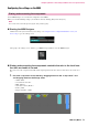
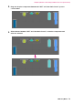
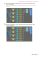
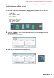
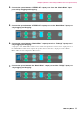
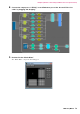
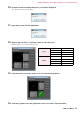
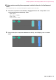
Table Of Contents
- Cover
- Introduction
- Setup workflow
- Example 1) Ballroom where the Room Combiner can be used
- Example 2) Remote conferencing system that also uses Speech Privacy
- Using the Device Configuration Wizard to create your device setup
- Configuring the settings on the MRX
- Making EXT. I/O settings
- Connecting the equipment
- Powering-on the MRX
- Powering-on the amp
- Specifying the computer’s TCP/IP address
- Sending the Speech Privacy environmental sound
- Taking MTX-MRX Editor online
- Verifying that the settings were applied
- Example 3) A paging system using the PGM1
- Using the Device Configuration Wizard to create your device setup
- Specifying the MRX configuration
- Making EXT. I/O settings
- Connecting the equipment
- Powering-on the PoE-equipped gigabit network switch
- Specifying the MCP1’s UNIT ID
- Power-on equipment other than amps and powered speakers
- Power-on amps and powered speakers
- Specifying the computer’s TCP/IP address
- Taking MTX-MRX Editor online
- Verifying that the settings were applied
- Q&A
- Uninstalling the software (Removing the application)

Example 2) Remote conferencing system that also uses Speech Privacy
MRX Setup Manual
71
Configuring the settings on the MRX
Use the MRX Designer to set an internal configuration on the MRX.
When you’ve finished making settings, you should save them by clicking [File] menu, then [Save].
Starting the MRX Designer
Click the tab for the system name that you set in step 1 of “Using the Device Configuration Wizard to create your
device setup” to go to the settings screen.
After going to the settings screen, click the [Open MRX Designer] button to start the MRX Designer.
Placing and connecting the components related to the mics in the local loca-
tion that send audio to far-end
Place and connect the components that will send the input signals from the mics in the local location to the remote loca-
tion.
1.
Place the components shown below by dragging them from the “Components” area
and dropping them into the Design sheet.
• “ANALOG IN”
• “Acoustic Echo Canceller”
• “HPF” (MONO)
• “Auto Gain Control” (MONO)
• “Fader” (8CH)
• “Dugan Automixer” (8CH)
Placing and connecting the components
NOTE
The “User Account Control” dialog box may appear. Click [Continue] or [Yes].