MTX5-D/MY4-AEC System Setup Manual By using the MTX5-D and the MY4-AEC, you can configure a remote conferencing system. Please read this manual when you want to configure a remote conferencing system using the MTX5-D and the MY4-AEC. This manual provides a simple explanation of the setup procedure, using the project file that is preinstalled in MTX Editor. Understanding how the inputs and outputs of the MTX5-D and the MY4-AEC are related will allow you to configure a system that meets your needs.
Introduction The MTX5-D/MY4-AEC system setup manual explains settings for when an MY4-AEC is installed in the MTX5-D’s [SLOT]. As examples, we will provide simple explanations of the typical setups described below. For detailed parameter settings, refer to “MTX Editor User’s Manual.” When you install MTX Editor, the four example files described here will be found in the following folders. 32-bit operating system C:\Program Files\Yamaha\MTX Editor\V*.*\ProjectFile 64-bit operating system C:\Program Fil
Introduction Example 1) One remote location, and four microphones in the meeting room Microphone 1 Analog OUT Meeting room XMV4140 Microphone 2 CODEC Microphone 3 Network Remote A YDIF Analog IN MTX5-D Analog IN/OUT Microphone 4 This is an example of one remote location with four or fewer local microphones. Use the AEC 4Mic 1RemoteLocation-*.mtx file. This example assumes that you’re using the following equipment.
Introduction Example 2) One remote location, and eight microphones in the meeting room Microphone 1 Meeting room Analog OUT XMV4140 Microphone 2 Microphone 3 YDIF Microphone 4 Analog IN MTX5-D Analog IN/OUT CODEC Network Remote A Microphone 5 Microphone 6 Microphone 7 Microphone 8 This is an example of one remote location with between five and eight local microphones. Use the AEC 8Mic 1RemoteLocation-*.mtx file. This example assumes that you’re using the following equipment.
Introduction Example 3) Four remote locations, and four microphones in the meeting room Analog OUT Meeting room XMV4140 Microphone 1 Microphone 2 CODEC A Network Remote A CODEC B Network Remote B CODEC C Network Remote C CODEC D Network Remote D YDIF Analog IN MTX5-D Analog IN/OUT Microphone 3 Microphone 4 This is an example of multiple remote locations, with four or fewer local microphones. Use the AEC 4Mic 4RemoteLocation-*.mtx file.
Introduction Example 4) Dividing between two meeting rooms and conferencing with separate locations Microphone 1 Analog OUT Meeting room ‘A’ XMV4140 Microphone 2 CODEC A Microphone 3 Network Remote A Network Remote B YDIF Analog IN MTX5-D Microphone 4 Analog IN/OUT Microphone 1 Meeting room ‘B’ Analog OUT Microphone 2 Microphone 3 CODEC B Microphone 4 This is an example in which participants are divided between two meeting rooms and are conferencing with separate locations.
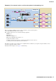
Example 1) One remote location, and four microphones in the meeting room Here we explain the main points when adjusting the example setup shown below. Microphone 1 Analog OUT Meeting room XMV4140 Microphone 2 CODEC Network Microphone 3 Remote A YDIF Analog IN MTX5-D Analog IN/OUT Microphone 4 In this example, the signal flow is as follows.
Example 1) One remote location, and four microphones in the meeting room For locations that are listed as having “Non-adjustable parameter,” you should avoid using Dynamics-type components (Gate, Comp, Ducker) and adjusting the parameters of an operating system after it has been set up. Echo cancellation will no longer work effectively if you do so. In this example, the connections are as follows.
Example 1) One remote location, and four microphones in the meeting room Example settings for MTX Editor • Distance setting For a simple configuration in which the distance between the microphone and speaker is within two meters, there is no need to change this setting in MTX Editor. If the distance between the microphone and speaker is greater than two meters, use the [Distance] knob to specify the distance.
Example 1) One remote location, and four microphones in the meeting room Examples of adjusting the settings • Adjusting the volume of the audio signal from the remote location Operate the fader of input channel 9. While you watch the level meter, adjust the input level so that the yellow indicator lights occasionally. • Adjusting the volume of a microphone of the local location In the “MY4-AEC” screen, click the [Near-end Mic.] button to access the parameter editing screen, and operate the [GAIN] knob.
Example 2) One remote location, and eight microphones in the meeting room Microphone 1 Meeting room Analog OUT XMV4140 Microphone 2 Microphone 3 YDIF Microphone 4 Analog IN MTX5-D Analog IN/OUT Network CODEC Remote A Microphone 5 Microphone 6 Microphone 7 Microphone 8 In this example, the signal flow is as follows.
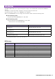
Example 2) One remote location, and eight microphones in the meeting room NE: FromFE: NEVoice: FEVoice: TO FE: NR: Near-end Mic From Far-end Near-end Voice Far-end Voice To Far-end Noise Reduction For locations that are listed as having “Non-adjustable parameter,” you should avoid using Dynamics-type components (Gate, Comp, Ducker) and adjusting the parameters of an operating system after it has been set up. Echo cancellation will no longer work effectively if you do so.
Example 2) One remote location, and eight microphones in the meeting room Example settings for MTX Editor • Distance setting For a simple configuration in which the distance between the microphone and speaker is within two meters, there is no need to change this setting in MTX Editor. If the distance between the microphone and speaker is greater than two meters, use the [Distance] knob to specify the distance.
Example 2) One remote location, and eight microphones in the meeting room Examples of adjusting the settings • Adjusting the volume of the audio signal from the remote location Operate the fader of input channel 9. While you watch the level meter, adjust the input level so that the yellow indicator lights occasionally. • Adjusting the volume of a microphone of the local location Operate the faders of input channels 17 through 24.
Example 3) Four remote locations, and four mics in the meeting room Analog OUT Meeting room XMV4140 Microphone 1 Microphone 2 CODEC A Network Remote A CODEC B Network Remote B CODEC C Network Remote C CODEC D Network Remote D YDIF Analog IN MTX5-D Analog IN/OUT Microphone 3 Microphone 4 In this example, the signal flow is as follows.
Example 3) Four remote locations, and four mics in the meeting room For locations that are listed as having “Non-adjustable parameter,” you should avoid using Dynamics-type components (Gate, Comp, Ducker) and adjusting the parameters of an operating system after it has been set up. Echo cancellation will no longer work effectively if you do so. In this example, the connections are as follows.
Example 3) Four remote locations, and four mics in the meeting room Example settings for MTX Editor • Distance setting For a simple configuration in which the distance between the microphone and speaker is within two meters, there is no need to change this setting in MTX Editor. If the distance between the microphone and speaker is greater than two meters, use the [Distance] knob to specify the distance.
Example 3) Four remote locations, and four mics in the meeting room Examples of adjusting the settings • Adjusting the volume of the audio signal from the remote location Operate the fader of input channels 9 through 12. While you watch the level meter, adjust the input level so that the yellow indicator lights occasionally. • Adjusting the volume of a microphone of the local location In the “MY4-AEC” screen, click the [Near-end Mic.
Example 4) Dividing between two meeting rooms and conferencing with separate locations Microphone 1 Analog OUT Meeting room ‘A’ XMV4140 Microphone 2 CODEC A Microphone 3 Network Remote A Network Remote B YDIF Analog IN MTX5-D Microphone 4 Analog IN/OUT Microphone 1 Meeting room ‘B’ Analog OUT Microphone 2 Microphone 3 CODEC B Microphone 4 MTX5-D/MY4-AEC System Setup Manual 19
Example 4) Dividing between two meeting rooms and conferencing with separate locations In this example, the signal flow is as follows.
Example 4) Dividing between two meeting rooms and conferencing with separate locations In this example, the connections are as follows.
Example 4) Dividing between two meeting rooms and conferencing with separate locations Example settings for MTX Editor • Distance setting For a simple configuration in which the distance between the microphone and speaker is within two meters, there is no need to change this setting in MTX Editor. If the distance between the microphone and speaker is greater than two meters, use the [Distance] knob to specify the distance.
Example 4) Dividing between two meeting rooms and conferencing with separate locations Examples of adjusting the settings • Adjusting the volume of the audio signal from the remote location For meeting room ‘A’, operate the fader of input channel 9. For meeting room ‘B’, operate the fader of input channel 10. While you watch the level meter, adjust the input level so that the yellow indicator lights occasionally.
Appendix Signal processing in the MY4-AEC The MY4-AEC acoustic echo canceller (AEC) works by comparing the reference signal received from the far-end with the signal from the microphone in order to determine which components of the signal are echo, and then subtracts only the farend echo component from microphone signal. The near-end sound is thus clearly transmitted to the far end without echo. The signal flow is as follows.