
User Manual
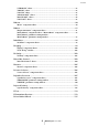
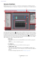
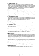
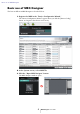
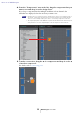
Table Of Contents
- Contents
- An overview of MRX Designer
- Screen structure
- Basic use of MRX Designer
- Menu bar
- Tool buttons
- Shortcut keys
- Design sheet
- “Parameter Sets” area
- “Parameter Link Group” area
- “Gang Edit Group” area
- “Properties” area
- Components and the component editor
- Editing the parameters
- Acoustic Echo Canceller (AEC)
- Ambient Noise Compensator (ANC)
- Audio Detector
- Auto Gain Controller (AGC)
- Combiner
- Delay
- Dynamics
- Effect
- EQ
- Fader
- Feedback Suppressor
- Filter
- Inputs/Outputs
- Meter
- Mixer
- Oscillator
- Paging
- Polarity
- Revolabs Control
- Router
- Source Selector
- Speaker Processor
- Speech Privacy
- Text
- Transmitter/Receiver
- User Defined Block
- Dialog boxes and applications
- “Print” dialog box
- “Install Speech Privacy File” dialog box
- “File Transfer” application
- “PGM1 Label Creator” application
- “Compile” dialog box
- “Snapshot Group” dialog box
- “Remote Control Setup List” dialog box
- “External Events” dialog box
- “GPI” dialog box
- “Digital Control Panel” dialog box / “Wireless DCP” dialog box / “MCP1” dialog box
- “PGM1/PGX1” dialog box
- “Port Name” dialog box
- List of settings in “Settings” dialog boxes
- Context menus
- Troubleshooting

Screen structure
MRX Designer User Guide
7
Screen structure
MRX Designer consists of a “menu bar,” “tool buttons,” “Components area,” “Parameter Sets area,”
“Parameter Link Group area,” “design sheet,” “Properties area,” “Parameters area,” and “Bird’s Eye view.”
In the upper right of each area is a “ ” symbol; when you click this, the area becomes an icon and is
placed at the left or right side of the screen, allowing the design sheet to occupy more of the screen. When
you place the cursor on this icon, the area is temporarily expanded. If you want to once again view an
iconized area in its fixed position, move the cursor over the icon and click the “ ” symbol that appears.
When you place the cursor on the border between the design sheet and an area, the cursor changes
shape, allowing you to drag to change the width of the area.
1 Menu bar
The commands that can be executed in MTX Editor can be found here, grouped by
category.
Click here to see a list of commands. (page 12)
2 Tool buttons
Frequently-used functions are provided here as buttons. (page 17)
3 “Components” area
This is a list of the components that can be used on the MRX. If you want to use a
component, drag and drop it onto the design sheet; it will be installed in the MRX as a
function.
For details on arranging components, refer to “Placing components.”
1
2
3
4
5
6
7
8
9
0
B
A