
User Manual


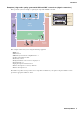


Table Of Contents
- Cover
- Introduction
- Setup workflow
- Example 1) Basic MTX3 system example (analog connections)
- Example 2) High audio quality system with XMV and YDIF connections (digital connections)
- Example 3) Using cascade mode to add MTX input channels (analog connection)
- Using the Device Configuration Wizard to create your device setup
- Making preliminary settings in MTX-MRX Editor
- Connecting the equipment
- Powering-on the MTX
- Powering-on the amp
- Setting the MCP1’s UNIT ID
- Specifying the computer’s TCP/IP address
- Taking MTX-MRX Editor online
- Making XMV settings
- Verifying that the settings were applied
- Example 4) A system using Dante
- Using the Device Configuration Wizard to create your device setup
- Making preliminary settings in MTX-MRX Editor
- Dante settings between systems
- Connecting the equipment
- Powering-on the MTX
- Powering-on the amp
- Specifying the computer’s TCP/IP address
- Taking MTX-MRX Editor online
- Making XMV settings
- Verifying that the settings were applied
- Example 5) A system using the PGM1 for paging
- Using the Device Configuration Wizard to create your device setup
- Making preliminary settings in MTX-MRX Editor
- Connecting the equipment
- Power-on the PoE-equipped gigabit network switch
- Power-on equipment other than amps and powered speakers
- Power-on amps and powered speakers
- Specifying the computer’s TCP/IP address
- Taking MTX-MRX Editor online
- Making XMV settings
- Verifying that the settings were applied
- Q&A
- Uninstalling the software (Removing the application)

MTX Setup Manual 2
The MTX Setup Manual explains how to create setups using the MTX and MTX-MRX Editor.
As examples, we will provide simple explanations of the typical setups described below.
For detailed parameter settings, refer to “MTX-MRX Editor User Guide” and to the owner’s manual and installation man-
ual of the XMV, MTX, DCP, MCP1, and PGM1.
When you install MTX-MRX Editor, the five example files described here will be found in the following folders.
32-bit operating system
C:\Program Files\Yamaha\MTX-MRX Editor\V*.*\ProjectFile
64-bit operating system
C:\Program Files(x86)\Yamaha\MTX-MRX Editor\V*.*\ProjectFile
*.* will be the version of the installed MTX-MRX Editor.
Example 1 : MTX3 basic system-*.mtx
Example 2 : MTX3 XMV digital system-*.mtx
Example 3 : MTX3+MCP1 cascade example-*.mtx
Example 4 : MTX5-D Dante system-*.mtx
Example 5 : MTX5-D+PGM1 Shopping mall-*.mtx
-* is a management number. In some cases, there will be no -*.
Example 1) Basic MTX3 system example (analog connections)
This example assumes that you’re using the following equipment.
The number of speakers is not specified; choose amps that are suitable for your speaker setup. You will also need to
provide the appropriate number of cables.
Introduction
DCP
ID=3
Kitchen
(Zone 4)
Hall A
(Zone 1)
Hall B
(Zone 2)
Entrance
(Zone 3)
DCP
ID=1
Microphone
Ch=2
Microphone
Ch=1
Microphone
Ch=4
DCP
ID=0
Amp
Room
DCP
ID=2
Microphone
Ch=3
MTX3 ID=01
CD Player
Power Amp 1
Power Amp 2
BGM Player
Wireless Microphone Reciever
•MTX3 × 1
• DCP1V4S × 4
• Amplifiers (four channels of amplification)
• Speakers (the number needed)
• SD memory card × 1
• Background music source such as a CD player × 1
• Paging microphones with switch × 2
• Wireless microphone receivers (2 channels)
• Wireless microphones × 2