Owner’s Manual EN
Explanation of Graphical Symbols The lightning flash with arrowhead symbol within an equilateral triangle is intended to alert the user to the presence of uninsulated “dangerous voltage” within the product’s enclosure that may be of sufficient magnitude to constitute a risk of electric shock to persons. CAUT I ON RISK OF ELECTRIC SHOCK DO NOT OPEN CAUTION: TO REDUCE THE RISK OF ELECTRIC SHOCK, DO NOT REMOVE COVER (OR BACK). NO USER-SERVICEABLE PARTS INSIDE. REFER SERVICING TO QUALIFIED SERVICE PERSONNEL.
FCC INFORMATION (U.S.A.) 1. IMPORTANT NOTICE: DO NOT MODIFY THIS UNIT! This product, when installed as indicated in the instructions contained in this manual, meets FCC requirements. Modifications not expressly approved by Yamaha may void your authority, granted by the FCC, to use the product. 2. IMPORTANT: When connecting this product to accessories and/or another product use only high quality shielded cables. Cable/s supplied with this product MUST be used. Follow all installation instructions.
PRECAUTIONS PLEASE READ CAREFULLY BEFORE PROCEEDING * Please keep this manual in a safe place for future reference. WARNING Always follow the basic precautions listed below to avoid the possibility of serious injury or even death from electrical shock, short-circuiting, damages, fire or other hazards.
NOTICE Information To avoid the possibility of malfunction/ damage to the product, damage to data, or damage to other property, follow the notices below. About this manual Handling and Maintenance • Do not use the device in the vicinity of a TV, radio, stereo equipment, mobile phone, or other electric devices. Otherwise, the device, TV, or radio may generate noise.
Contents PRECAUTIONS................................................................................................................4 Getting Started................................................................................................................7 Included items (please check) ................................................................................................ 7 Firmware versions.......................................................................................................
Getting Started Thank you for purchasing the Yamaha Matrix Processor MTX5-D. This manual will help you take full advantage of the superior functionality offered by the MTX5-D. After you have read the manual, keep it in a safe place for reference when needed. Included items (please check) • MTX5-D Owner’s Manual (this document) • Power cable • Euroblock plugs (16-pin, 3.50mm pitch) (2) • Euroblock plugs (3-pin, with tab, 5.
Introducing the MTX5-D Features • A signal processor suitable for small or mid-sized installed systems The MTX5-D is a signal processor suitable for small or midsized systems such as retail establishments or banquet halls. In addition to a 34 ch. x 16 ch. matrix mixer, it provides 3-band parametric EQ, compressor/gate, auto gain control, eight priority duckers, and eight feedback suppressors.
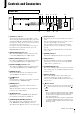
Controls and Connectors Front Panel q we t yu i !1 !2 !5 88 r q SD memory card slot o !0 !4 !3 !0 [SYNC] indicators You can insert an SD memory card here. Music or sound effects can be played back from an SD memory card containing audio files (MP3 files and WAV files). Before you insert an SD memory card into the slot, or remove an SD memory card from the slot, remove the slot cover. For details on SD memory card handling, refer to page 22.
Controls and Connectors Rear Panel q e w r ty u i o !0 !3 !1 !2 !4 t [RS-232C] connector NOTE The MTX5-D has some connectors that are shaped identically but have a completely different function (e.g., [DCP] connector, Dante [PRIMARY]/[SECONDARY] connectors, [YDIF] connectors). Make the appropriate connections as instructed by the explanation for each connector. Otherwise, you risk damaging your equipment. q AC IN connector Use the included power cord to supply power to this connector.
Controls and Connectors Switches 1–2 (UNIT ID) These switches specify the upper digit and the abovementioned [UNIT ID] rotary switch specifies the lower digit, together allowing you to specify one of 63 different UNIT ID numbers in a range from 01 to 3F. Switch position Option Functions UNIT ID is “0x” The [UNIT ID] rotary switch will have a setting range of 01 through 0F. UNIT ID is “1x” The [UNIT ID] rotary switch will have a setting range of 10 through 1F.
Controls and Connectors o [YDIF] connectors These connectors are used to make a ring connection with the devices that comprise the MTX/MRX system, allowing digital audio signals to be transmitted and received. Use CAT5e or better Ethernet STP cables (shielded twisted pair cables) that have all eight pins connected in a straight connection. The maximum cable length between devices is 30 meters, and you can connect up to eight devices that are equipped with the [YDIF] connectors.
Controls and Connectors Euroblock plug connection 1. Loosen the terminal screws. Use the included Euroblock plugs when making connections to the [INPUT]/[OUTPUT] connectors and [GPI] connector. Loosen Slotted screwdriver Cable preparation Terminal screw approx. 7 mm (approx. 5 mm for the GPI connector) Euroblock plug approx. 20 mm • Use stranded wire for Euroblock connections, and strip the wire as shown in the illustration.
Controls and Connectors 5. Plug the Euroblock plug into the [GPI] connector or [INPUT]/[OUTPUT] connector of the MTX5-D. 3. Align the edges of the card with the guide rails inside the slot, and insert the card into the slot. Push the card all the way into the slot so that the connector at the end of the card is correctly inserted into the connector inside the slot. NOTE When connecting unbalanced cables to the [INPUT] connector, use a jumper wire to connect the “-” and “G” of the Euroblock.
About Dante This product features Dante technology as a protocol to transmit audio signals. Dante is a network protocol developed by Audinate. It is designed to deliver multi-channel audio signals at various sampling and bit rates, as well as device control signals over a Giga-bit Ethernet (GbE) network. Dante also offers the following benefits: • It transmits up to 512 in/512 out, for a total 1024 channels (in theory) of audio over a GbE network.
About Dante About redundant networks About Dante Controller A redundant network consists of two circuits, a primary circuit and a secondary circuit. Normally, the network operates on the primary circuit. However, if the primary connection is broken, the secondary circuit will automatically take over communications. Therefore, using a redundant network with a star topology would increase resiliency against unexpected network problems relative to a daisy chain network.
Quick Guide This section explains basic settings and connection procedures for constructing an MTX/MRX system using the MTX5-D. Some of the steps may not be necessary for your system; if so, proceed to the next step. Preparations Use MTX-MRX Editor to make the required settings before you actually install and connect the equipment. 1. Prepare a computer in which to install MTXMRX Editor. 2. Install MTX-MRX Editor in your computer. For details on installation, refer to “MTX Setup Manual.” 7.
Quick Guide 8. Make DCP settings. Assign the parameters of the MTX5-D to the switches and knobs of the connected DCP units. Here you can also specify the brightness of the DCP’s LEDs. For details on how to make DCP settings, refer to “MTX-MRX Editor User Guide.” 9. As necessary, make settings for devices other than the MTX5-D. For details, refer to “MTX Setup Manual.” 10. Specify and store a preset. You can use presets to change the volume of zones and the audio source to play (e.g.
Quick Guide On-site work (Settings in MTX-MRX Editor) Use MTX-MRX Editor to make adjustments for the entire system. 1. Connect the computer to the MTX5-D/XMV/ EXi8/EXo8 via a network switch. If you’re using only the MTX5-D, you can connect it directly to the computer. 2. Start up MTX-MRX Editor and load the project file that you previously created. 3. Power-on the MTX5-D. 4. Power-on the XMV/EXi8/EXo8 and the analog input amps. 5.
Various Procedures Recalling (switching) presets Using the scheduler With the MTX/MRX system, input/output port patching, matrix mixer settings, and the parameters of XMV amps within the same MTX/MRX system are stored together as a “preset” in the MTX5-D and in MTX-MRX Editor for recall when desired. Each MTX/MRX system can store 50 presets. MTX-MRX Editor is used to edit presets. The scheduler can switch presets or play music and sound effects from the SD memory card at the date and time you specify.
Various Procedures Connecting via the [GPI] connector GPI (General Purpose Interface) devices can be connected to the rear-panel [GPI] connectors. GPI allows a variety of control signals to be exchanged with external controllers or other devices. • Connection examples using the [GPI IN] connector Example: Controlling the MTX5-D from a switch box MTX5-D +5VDC +V CPU IN A/D 100k Example: Controlling the MTX5-D with a 10k ohm linear taper potentiometer.
Various Procedures Using the MTX5-D to play audio files saved on an SD memory card The MTX5-D can use commercially available SD memory cards to play back audio files such as music and sound effects without needing to connect a CD player or other audio device. The MTX5-D can play back audio files in either MP3 or WAV formats. Initializing the MTX5-D Here’s how to initialize the MTX5-D’s internal memory, restoring it to the factory settings. 1. Power-off the MTX5-D. 2.
Various Procedures 4. When initialization is completed, power-off the MTX5-D once again. 5. Set the rear panel DIP switches 7 and 8 to the “RESUME” position. 6. Power-on the MTX5-D again. The MTX5-D will start up in its factory-set state.
Appendix Troubleshooting The Yamaha Pro Audio website provides a FAQ (a list of frequently asked questions, with answers). http://www.yamahaproaudio.com/ Symptom Possible cause, and action Connect the power cord properly. The device does not turn on, or the panel LEDs do not light up. Make sure that the power switch is turned on. If the power still does not turn on, contact your Yamaha dealer.
Appendix Symptom Preset does not switch at the time specified by the scheduler. The [ALERT] indicator is flashing. Can’t switch presets from a device connected to the [GPI] connector. Possible cause, and action The MTX5-D’s clock is set by sending clock data from the computer via MTX-MRX Editor to the MTX5-D. Make sure that the computer’s clock is set correctly.
Appendix Messages Warnings and certain other types of information are displayed via the MTX5-D front panel indicators. Messages are also displayed in the Dante Controller Error Status field. Each indicator lights or flashes as described below: Unlit The indicator is off. Lit The indicator remains lit steadily. Flash The indicator continues to flash. Flash x 2 The indicator flashes twice cyclically. Information Messages The status is shown by the lit/flashing state of the indicator.
Appendix Alert list This is a list of the alerts that may be indicated in the front panel [PRESET] display. Alert number Meaning Response 01–09 The device has not started up correctly. Turn the power off, then turn on after waiting at least 6 seconds. If this does not solve the problem, please initialize the memory. Should this also fails, contact your Yamaha dealer. 10 The internal backup battery has been completely exhausted or is not installed.
Appendix Alert number Meaning Response 50 The UNIT ID is set to “00.” Set the UNIT ID to something other than “00.” 51 Devices with identical UNIT IDs were found connected within the same network. Change the UNIT ID so that there are no duplicates. 52 A communication error occurred with the [DCP] connection. • If an error was shown in the DCP panel, refer to the DCP owner’s manual and take the appropriate action. • Ensure that the panel ID of the DCP units do not conflict.
Appendix Specifications Product specifications Dimensions (W x H x D) Weight Power supply voltage Power consumption Heat dissipation (per hour) Operating temperature range Storage temperature range NC value Number of memories Maximum number of simultaneously usable devices Power cord length Included items Separately sold options Electrical specifications Sampling frequency Signal delay Frequency response Total harmonic distortion Dynamic range Equivalent input noise (EIN) Crosstalk / Channel separation M
Appendix Input/Output Characteristics ANALOG INPUT CHARACTERISTICS Input Terminals INPUT 1–8 GAIN +66dB -6dB ST IN 1, 2 — Actual Load Impedance For Use With Nominal 10kΩ 10kΩ Input Level Connector Nominal Max. before clip 50–600Ω Mics & 600Ω Lines -62dBu (0.616mV) -42dBu (6.16mV) +10dBu (2.45V) +30dBu (24.5V) Euroblock (Balanced) (5.08mm pitch) 600Ω Lines -10dBV (316mV) +10dBV (3.16V) RCA Pin Jack • In these specifications, 0dBu = 0.775 Vrms., 0dBV = 1.00 Vrms.
DANTE Mini -YGDAI SD IN L-R 16 INPUT METER MTX5-D Owner’s Manual From OUTPUT CHANNEL 1-16 From DANTE IN 1-16 From SLOT IN 1-4 From SD IN L-R From ST IN 1L-2R From INPUT 1-8 From YDIF IN 1-16 EFFECT 2 16 16 4 2 4 8 16 To MY4-AEC INPUT PATCH* *MY4-AEC only 16 To INPUT CHANNEL INSERT INPUT INPUT METER SUM SUM INPUT METER INPUT METER From FX2 EFFECT AD AD 8 To PRIORITY/AMBIENT SOURCE To ROUTER IN To YDIF OUTPUT PATCH AD INPUT PATCH MY4-AEC INPUT PATCH DANTE IN 1-16 SLOT IN
Appendix Index Symbols +48V .......................................................................12 [s/t] buttons ...........................................................9 [ALERT] indicator .....................................................9 [DCP] connector .....................................................11 [ENTER] button ........................................................9 [GPI] connector ......................................................10 [INPUT PEAK] indicators .................
MTX5-D Owner’s Manual 33
ADDRESS LIST NETHERLANDS/BELGIUM/ LUXEMBOURG NORTH AMERICA CANADA Yamaha Music Europe Branch Benelux Clarissenhof 5b, 4133 AB Vianen, The Netherlands Tel: +31-347-358040 Yamaha Canada Music Ltd. 135 Milner Avenue, Toronto, Ontario, M1S 3R1, Canada Tel: +1-416-298-1311 FRANCE U.S.A. Yamaha Corporation of America 6600 Orangethorpe Avenue, Buena Park, CA 90620, U.S.A. Tel: +1-714-522-9011 CENTRAL & SOUTH AMERICA MEXICO Yamaha de México, S.A. de C.V. Av. Insurgentes Sur 1647 Piso 9, Col.
MEMO MTX5-D Owner’s Manual 35
Yamaha Pro Audio global website http://www.yamaha.com/proaudio/ Yamaha Downloads http://download.yamaha.