MTX Setup Manual This manual serves as an introduction to possible installation methods and application examples for the MTX series of DSP processors used in conjunction with MTX Editor control software. Please refer to the owner’s manual on a device about the details of MTX, and refer to the “MTX Editor User’s Manual” (PDF file) about the details of MTX Editor. Special Notice • The software and this manual are the exclusive copyrights of Yamaha Corporation.
Introduction The MTX Setup Manual explains how to create setups using the MTX and MTX Editor. As examples, we will provide simple explanations of the typical setups described below. For detailed parameter settings, refer to “MTX Editor User’s Manual” and to the owner’s manuals of the XMV, MTX, and DCP. When you install MTX Editor, the four example files described here will be found in the following folders. 32-bit operating system C:\Program Files\Yamaha\MTX Editor\V*.
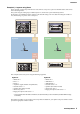
Introduction Example 2) High audio quality system with XMV and YDIF connections (digital connections) This repeats the system of example 1, replacing the amps with an XMV series unit.
Introduction Example 3) Using cascade mode to add MTX input channels (analog connection) Cascade mode allows the matrix buses to be shared between MTX units. This mode lets you use two MTX units to increase the number of inputs, and output the combined inputs to a single amp. In cascade mode, audio cannot be transmitted to the XMV via YDIF.
Introduction Example 4) A system using Dante In this example, existing amps continue to be used, while we set up a new system at a distant location, with connections made using Dante. The system using the existing amps is labeled System A, and the new system is labeled System B. In example 4, our explanation will be centered on the network settings. For more about increasing the number of mics, DCP settings, or presets, refer to example 2.
Setup workflow The following table shows the workflow for connecting equipment such as MTX series matrix mixers and XMV series power amplifiers to your computer, and making settings in MTX Editor.
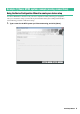
Setup workflow Follow the steps below to install MTX Editor. 1. After decompressing the downloaded file, double-click “setup.exe” in the decompressed file location. The MTX Editor setup wizard will appear. 2. Proceed with the installation as directed by the instructions in the screen. NOTE If the computer you’re using does not have Bonjour installed, a screen asking you to install Bonjour will appear during the installation.
Example 1) Basic MTX3 system example (analog connections) Using the Device Configuration Wizard to create your device setup You will use MTX Editor’s wizard to create your device setup before actually connecting your equipment. After you’ve made basic settings, you’ll be able to print information about system cabling and ID numbers. Use the following procedure to make basic settings. 1. Type a name for the MTX system you’ll be constructing, and click [Next>].
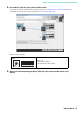
Example 1) Basic MTX3 system example (analog connections) 2. Specify the number of units that will be connected in your MTX system, and click [Next>]. In “YDIF Connected,” specify 1 as the number of MTX3 units. 3. Verify that the MTX’s UNIT ID is 1, and then click [Next>]. Unless you have specific reasons for doing so, use the UNIT ID that is assigned.
Example 1) Basic MTX3 system example (analog connections) 4. Set the MTX’s [UNIT ID] rotary switch and DIP switch. You will set the computer’s IP address after completing the wizard, in “Specifying the computer’s TCP/IP address.” If the MTX is not nearby, make settings during the step “Connecting the equipment.” Make the following settings. MTX3 UNIT ID = 01 [UNIT ID] rotary switch = 1 DIP switches are all OFF (upward) 5.
Example 1) Basic MTX3 system example (analog connections) 6. Verify that the MTX is shown, and click [Next>]. 7. Choose the model of DCP that is connected to the MTX, enter a device name, and click [Finish]. Since four DCP1V4S units will be connected, make settings for four units.
Example 1) Basic MTX3 system example (analog connections) 8. When you see the dialog box “Display the configuration diagram? The diagram can also be printed.” click [Yes]. A cabling diagram will appear. If you want, click [Print] to print the diagram. To close the screen, click [Close]. Set the DIP switches of the DCP units as shown in the “Digital Control Panel” section of the schematic diagram. For the last DCP (ID=3), set DIP switch 4 ON (upward).
Example 1) Basic MTX3 system example (analog connections) Making preliminary settings in MTX Editor Here’s how to make detailed MTX system settings in MTX Editor. When you’ve finished making settings, you should save them by clicking [File] menu, then [Save]. NOTE The “User Account Control” dialog box may appear. Click [Continue] or [Yes]. Specifying the MTX configuration Here you’ll specify how the MTX’s inputs and outputs will be handled.
Example 1) Basic MTX3 system example (analog connections) Settings in the “MAIN” screen In the “MAIN” screen you can make overall settings for each channel. For details on each parameter, refer to “MTX Editor User’s Manual.” Here you’ll make the following settings.
Example 1) Basic MTX3 system example (analog connections) INPUT settings Port select button Port/External Device parameter access button EQ/HPF FBS (Feedback suppressor) [ON] button Fader Channel name Port select button When you click this, the “Input Patch” dialog box will open. In this example we are using the default settings, but if you want to switch to a different input port of the MTX, click this button, choose the desired input port, and then click the [Close] button.
Example 1) Basic MTX3 system example (analog connections) OUTPUT settings Port select button Port/External Device parameter access button Port select button Click this to open the “Output Patch” dialog box. In this example we will use the default settings, but if you want to use a different output port of the MTX, click this button, choose the desired output port, and then click the [Close] button.
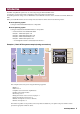
Example 1) Basic MTX3 system example (analog connections) Settings in the “MATRIX” screen Here you can specify which input channel will be sent to which zone. For details on send level and other parameters, refer to “MTX Editor User’s Manual.” In this example, make the settings shown in the above illustration. Clicking a cross point (a square area) or dragging cross points will switch it on/off. If you right-click on a cross point, a context menu appears.
Example 1) Basic MTX3 system example (analog connections) Settings in the “ZONE” screen In the “ZONE” screen you can make Priority DUCKER settings. The Priority Ducker function temporarily attenuates the inputs from other channels when audio is input from a specified input channel, ensuring that the audio from the specified input channel will be broadcast clearly. Priority is given in the order of “1st PRIORITY > 2nd PRIORITY >Matrix Out signals.
Example 1) Basic MTX3 system example (analog connections) Settings in the “ROUTER” screen In the “ROUTER” screen you can assign zones to outputs. In this example we will leave the default settings unchanged, since the assignments are ZONE1=OUTPUT 1, ZONE2=OUTPUT 2, ZONE3=OUTPUT 3, and ZONE4=OUTPUT 4.
Example 1) Basic MTX3 system example (analog connections) Digital Control Panel (DCP) settings Here’s how to assign functions to the DCP that is installed in each zone. To make these settings, choose the [Controller] menu item [Digital Control Panel]. Here we will use the example of the DCP located in Hall A of the Preset 01 Basic library. Use the drop down list at the top of the screen to select the DCP for which you want to make settings.
Example 1) Basic MTX3 system example (analog connections) Next click the [Copy] button, and then click “02 [No Data]” to select the second library item. With this selected, click the [Paste] button. The library item you created as “Basic” will be copied. After changing the PARAMETER of switch 1 to “01,” double-click “Basic” in “02 Basic” located in the left of the screen, and change the name of the library item to “Party.” (After you’ve entered the name, press the key to confirm the name change.
Example 1) Basic MTX3 system example (analog connections) Example settings for other DCP units ID of the DCP Library name 1 (Hall B) Basic 2 (Entrance) Party Switch 1 Switch 2 Switch 3 Same as ID=0 (Hall A) Switch 4 Knob 1 ZONE OUT Level (ZONE2) Same as ID=0 (Hall A) Basic Party 3 (Kitchen) Basic Party Input Ch ON (CH1) Input Ch ON (CH2) No Assign No Assign Input Ch Level (CH1) Input Ch Level (CH2) Storing a preset Now we’ll store the settings we’ve made up to this point as a preset.
Example 1) Basic MTX3 system example (analog connections) Up to this point, you made separate settings for zone 1 and zone 2. However in some cases, such as a party, you might want to remove the boundary between zone 1 and zone 2 so that they can be a single meeting area. In this case, make settings in the “ROUTER” screen to route zone 1 to output 2, so that zone 1 and zone 2 can be used as a single space.
Example 1) Basic MTX3 system example (analog connections) If you store these settings as a different preset, you’ll be able to easily switch to settings suitable for a party. If you use Recall Filter to specify that only ROUTER and DCP settings are recalled, other settings such as gain will remain at the Basic settings even if you recall a party preset. This completes settings in the offline state. Save the settings once again.
Example 1) Basic MTX3 system example (analog connections) Connecting the equipment After you’ve rack-mounted the MTX and your other equipment, connect the MTX and the other equipment as shown below. If you’ve copied audio sources to an SD memory card, insert the card into the MTX now.
Example 1) Basic MTX3 system example (analog connections) Specifying the computer’s TCP/IP address To allow the MTX and the computer to communicate, specify the computer’s TCP/IP as follows. 1. On the [System] menu, click [Network Setup]. The “Network Setup” dialog box will appear. 2. Click [Open Network Connection]. “Network Connections” will appear. 3. Right-click the adapter to which the MTX is connected, and choose [Properties]. The “Local Area Connection Properties” dialog box will appear. 4.
Example 1) Basic MTX3 system example (analog connections) Taking MTX Editor online In the upper right of MTX Editor, click the [Online] button. When the unit has successfully come online, the indicator 1 will light blue. When the “Synchronization” dialog box appears, select “To Device,” and click the [OK] button. When the indication in the dialog box has switched, select the system that you want to place online, and click the [Online] button. The project created in MTX Editor will be sent to the MTX.
Example 1) Basic MTX3 system example (analog connections) Verifying that the settings were applied The main items to verify are listed below. For details on each parameter setting, refer to “MTX Editor User’s Manual.” 1. 2. Recall the Basic preset. Using the oscillator in the “ROUTER” screen, adjust the output level. Adjust the amp’s attenuator value to an appropriate level. 3. Specify the gain from the microphone.
Example 2) High audio quality system with XMV and YDIF connections (digital connections) Using the Device Configuration Wizard to create your device setup You will use MTX Editor’s wizard to create your device setup before actually connecting your equipment. After you’ve made basic settings, you’ll be able to print information about system cabling and ID numbers. Use the following procedure to make basic settings. 1. Type a name for the MTX system you’ll be constructing, and click [Next>].
Example 2) High audio quality system with XMV and YDIF connections (digital connections) 2. Specify the number of units that will be connected in your MTX system, and click [Next>]. Specify “1” as the number of MTX3 units in “YDIF Connected,” and specify “1” as the number of XMV4280 units to be connected. 3. Specify the UNIT ID of each device, and click [Next>]. Unless you have specific reasons for doing so, use the UNIT ID that is assigned.
Example 2) High audio quality system with XMV and YDIF connections (digital connections) 4. Set the [UNIT ID] rotary switch and DIP switch of the MTX and XMV. You will set the computer’s IP address after completing the wizard, in “Specifying the computer’s TCP/IP address.” If the MTX and XMV are not nearby, you can set them during the step “Connecting the equipment.” Make the following settings.
Example 2) High audio quality system with XMV and YDIF connections (digital connections) 6. Verify that the MTX and XMV are shown in the screen, and click [Next>]. Since there is only one MTX unit and one XMV unit, there’s no need to change the order. 7. Choose the model of DCP that is connected to the MTX, enter a device name, and click [Finish]. Since four DCP1V4S units will be connected, make settings for four units.
Example 2) High audio quality system with XMV and YDIF connections (digital connections) 8. When you see the dialog box “Display the configuration diagram? The diagram can also be printed.” click [Yes]. A cabling diagram will appear. If you want, click [Print] to print the diagram. To close the screen, click [Close]. Set the DIP switches of the DCP units as shown in the “Digital Control Panel” section of the schematic diagram. For the last DCP (ID=3), set DIP switch 4 ON (upward).
Example 2) High audio quality system with XMV and YDIF connections (digital connections) Making preliminary settings in MTX Editor Here’s how to make detailed MTX system settings in MTX Editor. When you’ve finished making settings, you should save them by clicking [File] menu, then [Save]. NOTE The “User Account Control” dialog box may appear. Click [Continue] or [Yes]. Making EXT. I/O settings Here you’ll make settings for inputting digital audio into the XMV.
Example 2) High audio quality system with XMV and YDIF connections (digital connections) 2. Verify that for the MTX with UNIT ID = 01, the buttons located below YDIF 1 through YDIF 4 are set to OUT1 (OUTPUT 1) through OUT 4 (OUTPUT 4) respectively. If the settings are different, click the button and change the setting. 3. In the lower left, click the [EDIT] button. Now you can specify the outputs from the MTX to YDIF 1–8.
Example 2) High audio quality system with XMV and YDIF connections (digital connections) 4. Click the output routing select button located below YDIF 1. The “YDIF Out Patch” dialog box will appear. 5. For CHANNEL, click [A] button. The YDIF 1 output routing select button shows that the YDIF 1 output has been assigned to CH A of the UNIT ID=1A XMV.
Example 2) High audio quality system with XMV and YDIF connections (digital connections) 6. Change the output destination in the [YDIF Out:] list box, to assign YDIF 2 through YDIF 4 to CH B through CH D of the XMV and then click [Close] button. 7. In the lower left, click [EDIT] button to lock the settings.
Example 2) High audio quality system with XMV and YDIF connections (digital connections) Specifying the MTX configuration Here you’ll specify how the MTX’s inputs and outputs will be handled. On the [System] menu, click [MTX Configuration] to open the “MTX Configuration” dialog box. The default settings are shown in the screen below. You can change them as necessary. In this example, we’ll use the default settings without change.
Example 2) High audio quality system with XMV and YDIF connections (digital connections) Settings in the “MAIN” screen In the “MAIN” screen you can make overall settings for each channel. Click the [01 MTX3] button to access the MTX “MAIN” screen. For details on each parameter, refer to “MTX Editor User’s Manual.” Here you’ll make the following settings.
Example 2) High audio quality system with XMV and YDIF connections (digital connections) INPUT settings Port select button Port/External Device parameter access button EQ/HPF FBS (Feedback suppressor) [ON] button Fader Channel name Port select button When you click this, the “Input Patch” dialog box will open.
Example 2) High audio quality system with XMV and YDIF connections (digital connections) OUTPUT settings Port select button Port / External Device parameter access button DELAY/Room EQ Speaker processor [ON] button Fader Port select button Click this to open the “Output Patch” dialog box. In this example we will use the default settings, but if you want to use a different output port of the MTX, click this button, choose the desired output port, and then click the [Close] button.
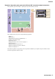
Example 2) High audio quality system with XMV and YDIF connections (digital connections) Settings in the “MATRIX” screen Here you can specify which input channel will be sent to which zone. For details on send level and other parameters, refer to “MTX Editor User’s Manual.” In this example, make the settings shown in the above illustration. Clicking a cross point (a square area) or dragging cross points will switch it on/off. If you right-click on a cross point, a context menu appears.
Example 2) High audio quality system with XMV and YDIF connections (digital connections) Settings in the “ZONE” screen In the “ZONE” screen you can make Priority DUCKER settings. The Priority Ducker function temporarily attenuates the inputs from other channels when audio is input from a specified input channel, ensuring that the audio from the specified input channel will be broadcast clearly. Priority is given in the order of “1st PRIORITY > 2nd PRIORITY >Matrix Out signals.
Example 2) High audio quality system with XMV and YDIF connections (digital connections) Settings in the “ROUTER” screen In the “ROUTER” screen you can assign zones to outputs. In this example we will leave the default settings unchanged, since the assignments are ZONE1=OUTPUT 1, ZONE2=OUTPUT 2, ZONE3=OUTPUT 3, and ZONE4=OUTPUT 4.
Example 2) High audio quality system with XMV and YDIF connections (digital connections) Digital Control Panel (DCP) settings Here’s how to assign functions to the DCP that is installed in each zone. To make these settings, choose the [Controller] menu item [Digital Control Panel]. Here we will use the example of the DCP located in Hall A of the Preset 01 Basic library. Use the drop down list at the top of the screen to select the DCP for which you want to make settings.
Example 2) High audio quality system with XMV and YDIF connections (digital connections) Next click the [Copy] button, and then click “02 [No Data]” to select the second library item. With this selected, click the [Paste] button. The library item you created as “Basic” will be copied. After changing the PARAMETER of switch 1 to “01,” double-click “Basic” in “02 Basic” located in the left of the screen, and change the name of the library item to “Party.
Example 2) High audio quality system with XMV and YDIF connections (digital connections) Example settings for other DCP units ID of the DCP Library name 1 (Hall B) Basic 2 (Entrance) Party Switch 1 Switch 2 Switch 3 Same as ID=0 (Hall A) Switch 4 Knob 1 ZONE OUT Level (ZONE2) Same as ID=0 (Hall A) Basic Party 3 (Kitchen) Basic Party Input Ch ON (CH1) Input Ch ON (CH2) No Assign No Assign Input Ch Level (CH1) Input Ch Level (CH2) Storing a preset Now we’ll store the settings we’ve made u
Example 2) High audio quality system with XMV and YDIF connections (digital connections) Up to this point, you made separate settings for zone 1 and zone 2. However in some cases, such as a party, you might want to remove the boundary between zone 1 and zone 2 so that they can be a single meeting area. In this case, make settings in the “ROUTER” screen to route zone 1 to output 2, so that zone 1 and zone 2 can be used as a single space.
Example 2) High audio quality system with XMV and YDIF connections (digital connections) If you store these settings as a different preset, you’ll be able to easily switch to settings suitable for a party. If you use Recall Filter to specify that only ROUTER and DCP settings are recalled, other settings such as gain will remain at the Basic settings even if you recall a party preset. For External I/O as well, press the [All Off] button so that all settings are carried over.
Example 2) High audio quality system with XMV and YDIF connections (digital connections) Connecting the equipment After you’ve rack-mounted the MTX and your other equipment, connect the MTX and the other equipment as shown below. If you’ve copied audio sources to an SD memory card, insert the card into the MTX now.
Example 2) High audio quality system with XMV and YDIF connections (digital connections) Powering-on the MTX Turn on the power of the MTX. Turn off the amplifier before you power-off the MTX. Powering-on the amp On the rear panel of the XMV, set the [SPEAKERS] DIP switch, and then turn on the power of the amps (XMV). To prevent unwanted sound from being output, we recommend that you turn down the attenuator settings of all channels on the amp itself before you turn it on.
Example 2) High audio quality system with XMV and YDIF connections (digital connections) 6. In the [IP address] box, enter “192.168.0.253”; in the [Subnet mask] box, enter “255.255.255.0.” NOTE The MTX3’s IP address is set to “192.168.0.1,” and the XMV’s IP address is set to “192.168.0.26.” 7. Click [OK]. NOTE In some cases, Windows firewall may block MTX Editor when you make this setting. Select the [Private Network] check box, and click [Allow Access].
Example 2) High audio quality system with XMV and YDIF connections (digital connections) Making XMV settings If necessary, use the XMV’s front panel to make settings such as the high pass filter. For more about the settings you can make on the XMV, refer to the XMV owner’s manual. Verifying that the settings were applied The main items to verify are listed below. For details on each parameter setting, refer to “MTX Editor User’s Manual.” 1. 2. Recall the Basic preset.
Example 3) Using cascade mode to add MTX input channels (analog connection) Using the Device Configuration Wizard to create your device setup You will use MTX Editor’s wizard to create your device setup before actually connecting your equipment. After you’ve made basic settings, you’ll be able to print information about system cabling and ID numbers. Use the following procedure to make basic settings. 1. Type a name for the MTX system you’ll be constructing, and click [Next>].
Example 3) Using cascade mode to add MTX input channels (analog connection) 2. Specify the number of units that will be connected in your MTX system, and click [Next>]. Specify “2” as the number of “YDIF Connected” MTX3 units, and specify “1” as the number of “ANALOG Connected” XMV4280. 3. Specify the YDIF MODE to CASCADE, and then click [Next>]. A dialog box will appear when you change this to CASCADE; click [OK]. Unless you have specific reasons for doing so, use the UNIT ID that is assigned.
Example 3) Using cascade mode to add MTX input channels (analog connection) 4. Set the [UNIT ID] rotary switch and DIP switch of the MTX and XMV. You will set the computer’s IP address after completing the wizard, in “Specifying the computer’s TCP/IP address.” If the MTX and XMV are not nearby, you can set them during the step “Connecting the equipment.” Make the following settings.
Example 3) Using cascade mode to add MTX input channels (analog connection) 6. Verify that the MTX and XMV are shown in the screen, and click [Next>]. 7. Choose the model of DCP that is connected to the MTX, enter a device name, and click [Finish]. Since one DCP1V4S will be connected to the UNIT ID=01 MTX3, choose [01 MTX3] for Device, and register the one DCP unit.
Example 3) Using cascade mode to add MTX input channels (analog connection) 8. When you see the dialog box “Display the configuration diagram? The diagram can also be printed.” click [Yes]. A cabling diagram will appear. If you want, click [Print] to print the diagram. To close the screen, click [Close]. Set the DIP switches of the DCP units as shown in the “Digital Control Panel” section of the schematic diagram. For the last DCP (ID=0), set DIP switch 4 ON (upward).
Example 3) Using cascade mode to add MTX input channels (analog connection) Making preliminary settings in MTX Editor Here’s how to make detailed MTX system settings in MTX Editor. When you’ve finished making settings, you should save them by clicking [File] menu, then [Save]. NOTE The “User Account Control” dialog box may appear. Click [Continue] or [Yes]. Making EXT. I/O settings Here you’ll make settings for inputting analog audio into the XMV.
Example 3) Using cascade mode to add MTX input channels (analog connection) 2. Click the [ANALOG] button. The MTX analog output setting screen will appear. Step 3 3. Click the button located below OUT1. The “Line Out Patch” dialog box will appear.
Example 3) Using cascade mode to add MTX input channels (analog connection) 4. Click the “CHANNEL” [A] button. The screen will show that with these settings, analog output 1 of the ID=01 MTX is connected to the CH A analog input of the XMV. 5. Change the output destination in the [Out:] list box, to assign CH B through CH D of the XMV to OUT 2 through OUT 4, and then click the [Close] button.
Example 3) Using cascade mode to add MTX input channels (analog connection) Specifying the MTX configuration Here you’ll specify how the MTX’s inputs and outputs will be handled. On the [System] menu, click [MTX Configuration] to open the “MTX Configuration” dialog box. The default settings are shown in the screen below. You can change them as necessary. In this example, we’ll use the default settings without change.
Example 3) Using cascade mode to add MTX input channels (analog connection) Settings in the “MAIN” screen In the “MAIN” screen you can make overall settings for each channel. For details on each parameter, refer to “MTX Editor User’s Manual.” You’ll make these settings for both MTX units, UNIT ID=01 and UNIT ID=02. Here you’ll make the following settings.
Example 3) Using cascade mode to add MTX input channels (analog connection) ID=02 MTX Setup Manual 64
Example 3) Using cascade mode to add MTX input channels (analog connection) INPUT settings Port select button Port/External Device parameter access button EQ/HPF FBS (Feedback suppressor) [ON] button Fader Channel name Port select button When you click this, the “Input Patch” dialog box will open. In this example we are using the default settings, but if you want to switch to a different input port of the MTX, click this button, choose the desired input port, and then click the [Close] button.
Example 3) Using cascade mode to add MTX input channels (analog connection) OUTPUT settings Port select button Port select button Click this to open the “Output Patch” dialog box. In this example we will use the default settings, but if you want to use a different output port of the MTX, click this button, choose the desired output port, and then click the [Close] button.
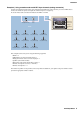
Example 3) Using cascade mode to add MTX input channels (analog connection) Settings in the “MATRIX” screen Here you can specify which input channel will be sent to which zone. For details on send level and other parameters, refer to “MTX Editor User’s Manual.
Example 3) Using cascade mode to add MTX input channels (analog connection) In this example, make the settings shown in the above illustration. Clicking a cross point (a square area) or dragging cross points will switch it on/off. If you right-click on a cross point, a context menu appears. You can select [All OFF] to turn off all cross points. The cross point shows the send level as the amount of green.
Example 3) Using cascade mode to add MTX input channels (analog connection) Settings in the “ZONE” screen In the “ZONE” screen you can make Priority DUCKER settings. The Priority Ducker function temporarily attenuates the inputs from other channels when audio is input from a specified input channel, ensuring that the audio from the specified input channel will be broadcast clearly. Priority is given in the order of “1st PRIORITY > 2nd PRIORITY >Matrix Out signals.
Example 3) Using cascade mode to add MTX input channels (analog connection) Settings in the “ROUTER” screen In the “ROUTER” screen you can assign zones to outputs. In this example, since ZONE1 will be output to OUTPUT1 through 4, set the MTX units of ID=01 and 02 as shown in the illustration.
Example 3) Using cascade mode to add MTX input channels (analog connection) Settings in the “DCA” screen (INPUT CH MUTE) In the “DCA” screen you can make level and mute settings for multiple channels in a single operation. ID=01 ID=02 In this example, press the [INPUT CH MUTE] button on the digital control panel at the chairman’s seat to mute all microphones other than the chairman’s microphone. Turn on CH1 through CH7 of ID=01, and CH1 through CH4 of ID=02.
Example 3) Using cascade mode to add MTX input channels (analog connection) Digital Control Panel (DCP) settings Here we’ll assign functions to the DCP that is located at the chairman’s seat. To make these settings, choose the [Controller] menu item [Digital Control Panel]. When you click one of the numbered buttons, a “Settings” dialog box will appear; assign parameters to the controls. When you’ve made the assignments, click to select “01 [No data]” and then click the [Store] button.
Example 3) Using cascade mode to add MTX input channels (analog connection) Storing a preset Now we’ll store the settings we’ve made up to this point as a preset. By recalling presets from the MTX itself or from the DCP, you can switch the settings as appropriate for various situations. To store or recall a preset, click the camera icon in the upper part of MTX Editor. When you click the camera icon, the “Preset” dialog box will appear. You can create up to 50 presets.
Example 3) Using cascade mode to add MTX input channels (analog connection) NOTE If you don’t store the preset, alert number 61 will occur. Up to this point, our settings use all of the microphones connected to MTX units of UNIT ID =01 and 02, but there might be cases in which you want to use a different number of microphones. In such cases, you can limit the number of microphones by turning off the channels of unused microphones in the “MAIN” screen.
Example 3) Using cascade mode to add MTX input channels (analog connection) ID=01 ID=02 If you store these settings as a different preset, you’ll be able to easily switch to settings with a limited number of microphones. In the example above, wireless microphones 9 through 11 are not used, so FBS is used on all of the wireless microphones (1 through 8) that are being used. This completes settings in the offline state. Save the settings once again.
Example 3) Using cascade mode to add MTX input channels (analog connection) Connecting the equipment After you’ve rack-mounted the MTX and your other equipment, connect the MTX and the other equipment as shown below. If you’ve copied audio sources to an SD memory card, insert the card into the MTX now.
Example 3) Using cascade mode to add MTX input channels (analog connection) Powering-on the MTX Turn on the power of the MTX. Turn off the amplifier before you power-off the MTX. Powering-on the amp On the rear panel of the XMV, set the [SPEAKERS] DIP switch, and then turn on the power of the amps (XMV). To prevent unwanted sound from being output, we recommend that you turn down the attenuator settings of all channels on the amp itself before you turn it on.
Example 3) Using cascade mode to add MTX input channels (analog connection) 6. In the [IP address] box, enter “192.168.0.253”; in the [Subnet mask] box, enter “255.255.255.0.” NOTE The MTX3’s IP address is set to “192.168.0.1” and “192.168.0.2,” and the XMV’s IP address is set to “192.168.0.26.” 7. Click [OK]. NOTE In some cases, Windows firewall may block MTX Editor when you make this setting. Select the [Private Network] check box, and click [Allow Access].
Example 3) Using cascade mode to add MTX input channels (analog connection) Making XMV settings If necessary, use the XMV’s front panel to make settings such as the high pass filter. For more about the settings you can make on the XMV, refer to the XMV owner’s manual. Verifying that the settings were applied The main items to verify are listed below. For details on each parameter setting, refer to “MTX Editor User’s Manual.” 1. 2. Recall the Basic preset.
Example 4) A system using Dante This example assumes an audio signal flow like the one shown below. System A Power Amp CH1 EXi8 Main Microphone OUTPUT 1 (YDIF) MTX5-D INPUT 1 (YDIF) OUTPUT 1–4 (Analog) OUTPUT 5–8 (YDIF) OUTPUT 9/10 (Dante) : Channel 9 is the main microphone for System A. INPUT 9/10 (Dante) : Channel 9 is the main microphone for System B.
Example 4) A system using Dante Using the Device Configuration Wizard to create your device setup You will use MTX Editor’s wizard to create your device setup before actually connecting your equipment. After you’ve made basic settings, you’ll be able to print information about system cabling and ID numbers. Make basic settings for System A, and then make basic settings for System B. Use the following procedure to make basic settings. 1.
Example 4) A system using Dante 3. Specify the UNIT ID of each device, and click [Next>]. Unless you have specific reasons for doing so, use the UNIT ID that is assigned. 4. Select the Mini-YGDAI card, and click [NEXT>]. In this example we are not using a Mini-YGDAI card, so leave the setting at [No Assign] and click [Next>].
Example 4) A system using Dante 5. Set the [UNIT ID] rotary switch and DIP switch of the devices. You will set the computer’s IP address after completing the wizard, in “Specifying the computer’s TCP/IP address.” If the devices are not nearby, you can set them during the step “Connecting the equipment.” Make the following settings.
Example 4) A system using Dante 7. Verify that the devices are shown in the screen, and click [Next>]. 8. Choose the model of DCP that is connected to the MTX, enter a device name, and click [Finish]. In this example we are not using a DCP, so leave the settings as they are.
Example 4) A system using Dante 9. When you see the dialog box “Display the configuration diagram? The diagram can also be printed.” click [Yes]. A cabling diagram will appear. If you want, click [Print] to print the diagram. To close the screen, click [Close]. NOTE If you want to view the cabling diagram again, do so by choosing [File] menu [Print Configuration Diagram].
Example 4) A system using Dante 10. In order to make basic settings for System B, click the system select tab [2 No Assign]. Step 11 11. System select tabs Click [Device Config]. The Device Configuration Wizard for System B will appear. 12. Enter a name for the MTX system that we are calling System B, and then click [NEXT>].
Example 4) A system using Dante 13. Specify the number of units that will be connected in your MTX system, and click [Next>]. In the “YDIF Connected” area, specify 1 each as the number of MTX5-D and XMV4280 units; in the “Dante Connected” area, specify 1 as the number of XMV4280-D devices. 14. Specify the UNIT ID of each device, and click [Next>]. Unless you have specific reasons for doing so, use the UNIT ID that is assigned.
Example 4) A system using Dante 15. Select the Mini-YGDAI card, and click [NEXT>]. In this example we are not using a Mini-YGDAI card, so leave the setting at [No Assign] and click [Next>]. 16. Set the [UNIT ID] rotary switch and DIP switch of the devices. You will set the computer’s IP address after completing the wizard, in “Specifying the computer’s TCP/IP address.” If the devices are not nearby, you can set them during the step “Connecting the equipment.
Example 4) A system using Dante Make the following settings. MTX5-D UNIT ID = 04 [UNIT ID] rotary switch = 4 DIP switches are all OFF (upward) XMV4280 UNIT ID = 30 [UNIT ID] rotary switch = 0 DIP switch 1 and 2 are ON (downward), others are OFF (upward) XMV4280-D [HIGH] UNIT ID = 31 [UNIT ID] rotary switch [HIGH] = 3 [UNIT ID] rotary switch [LOW] = 1 [LOW] NOTE On the XMV4280, the higher digit of the UNIT ID is set by the DIP switch, and the lower digit is set by the [UNIT ID] rotary switch.
Example 4) A system using Dante 18. Verify that the devices are shown in the screen, and click [Next>]. 19. Choose the model of DCP that is connected to the MTX, enter a device name, and click [Finish]. In this example we are not using a DCP, so leave the settings as they are.
Example 4) A system using Dante 20. When you see the dialog box “Display the configuration diagram? The diagram can also be printed.” click [Yes]. A cabling diagram will appear. If you want, click [Print] to print the diagram. To close the screen, click [Close]. NOTE If you want to view the cabling diagram again, do so by choosing [File] menu [Print Configuration Diagram].
Example 4) A system using Dante Making preliminary settings in MTX Editor Here’s how to make detailed MTX system settings in MTX Editor. When you’ve finished making settings, you should save them by clicking [File] menu, then [Save]. NOTE The “User Account Control” dialog box may appear. Click [Continue] or [Yes]. To switch between System A and System B, use the system select tabs in the “Project” screen. The currently selected MTX system is indicated by the system select tabs and the SYSTEM tab.
Example 4) A system using Dante We’ll start by making settings for System A. Making EXT. I/O settings Make settings for inputting and outputting digital audio. First we will make YDIF settings for System A. Click the SYSTEM tab to access the setting screen. 1. Click the [EXT. I/O] button. The “EXT. I/O” screen will appear, allowing you to make input/output settings for the external devices.
Example 4) A system using Dante 4. For CHANNEL, click [1] and then click [Close] button. The YDIF 1 input routing select button shows that CH1 of the EXi8 whose UNIT ID = 02 has been assigned to YDIF 1. 5. In the upper left, click [EDIT] to lock the settings.
Example 4) A system using Dante 6. Verify that for the MTX5-D with UNIT ID = 01, the buttons located below YDIF 5 through YDIF 8 are set to OUT5 (OUTPUT 5) through OUT 8 (OUTPUT 8) respectively. If the settings are different, click the button and change the setting. 7. In the lower left, click the [EDIT] button. Now you can specify the outputs from the MTX to YDIF 1–8.
Example 4) A system using Dante 8. Click the output routing select button located below YDIF 5. The “YDIF Out Patch” dialog box will appear. 9. For CHANNEL, click [1] button. The YDIF 5 output routing select button shows that the YDIF 5 output has been assigned to CH 1 of the UNIT ID=03 EXo8.
Example 4) A system using Dante 10. Change the output destination in the [YDIF Out:] list box, to assign YDIF 6 through YDIF 8 to CH 2 through CH 4 of the EXo8, and then click “Close” button. 11. In the lower left, click [EDIT] button to lock the settings.
Example 4) A system using Dante Settings in the “MAIN” screen In the “MAIN” screen you can make overall settings for each channel. Click the [01 MTX5-D] button to access the MTX “MAIN” screen. For details on each parameter, refer to “MTX Editor User’s Manual.” Here you’ll make the following settings.
Example 4) A system using Dante INPUT settings Make the following input settings.
Example 4) A system using Dante OUTPUT settings Make the following output settings.
Example 4) A system using Dante Settings in the “MATRIX” screen Here you can specify which input channel will be sent to which zone. For details on send level and other parameters, refer to “MTX Editor User’s Manual.” When making settings for System A, “this MTX system” refers to System A, and “the other MTX system” refers to System B. When making settings for System B, “this MTX system” refers to System B, and “the other MTX system” refers to System A.
Example 4) A system using Dante In this example, make the settings shown in the illustration in before page. Clicking a cross point (a square area) or dragging cross points will switch it on/off. If you right-click on a cross point, a context menu appears. You can select [All OFF] to turn off all cross points. The cross point shows the send level as the amount of green. For each zone, this setting will be as follows.
Example 4) A system using Dante Settings in the “ZONE” screen In the “ZONE” screen you can make Priority DUCKER settings. The Priority Ducker function temporarily attenuates the inputs from other channels when audio is input from a specified input channel, ensuring that the audio from the specified input channel will be broadcast clearly. Priority is given in the order of “1st PRIORITY > 2nd PRIORITY > Matrix Out signals.
Example 4) A system using Dante Settings in the “ROUTER” screen In the “ROUTER” screen you can assign zones to outputs. In this example, set ZONE1=OUTPUT 1 through 8, ZONE2=OUTPUT 9, and ZONE3=OUTPUT 10. With these settings, this MTX system will broadcast all of its own audio as well as all audio of the other MTX system, the main mic of this MTX system will be sent to Dante channel 9, and signals of this MTX system other than the main mic will be sent to Dante channel 10.
Example 4) A system using Dante Next we will make settings for System B. System B will have many of the same settings as System A. For the System B settings, we will explain settings made in the “EXT I/O” screen and settings made in the “MAIN” screen. Other settings will be the same as previously explained. If you’ve also finished the settings for System B, proceed to “Dante settings between systems.” First, select System B in the “Project” screen.
Example 4) A system using Dante Making EXT. I/O settings Make settings for inputting and outputting digital audio. First make YDIF and Dante settings for System B. Click the SYSTEM tab to access the setting screen. 1. Click the [EXT. I/O] button. The “EXT. I/O” screen will appear, allowing you to make input/output settings for the external devices. Since you’ll be making settings for YDIF 1–8, there’s no need to switch screens; simply make the settings in this screen. 2.
Example 4) A system using Dante 4. For CHANNEL, click [A] button. The YDIF 1 output routing select button shows that the YDIF 1 output has been assigned to CH A of the UNIT ID=30 XMV4280. 5. Change the output destination in the [YDIF Out:] list box, to assign YDIF 2 through YDIF 4 to CH B through CH D of the XMV4280, and then click [Close] button.
Example 4) A system using Dante 6. In the lower left, click [EDIT] button to lock the settings. [EDIT] button 7. Click [DANTE] button. The Dante setting screen will appear. Here you will specify the output to the XMV4280-D.
Example 4) A system using Dante 8. In the lower left, click the [EDIT] button. Now you can specify the outputs from the MTX to Dante. If the [Preserve the Dante settings configured by Dante Controller] check box is selected, clear the check box. 9. Click the output routing select button located below D OUT 5. The “Dante Out Patch” dialog box will appear.
Example 4) A system using Dante 10. In “[System B]31 XMV428 ...”, click [A]. The D OUT 5 output routing select button shows that the Dante 5 output has been assigned to CH A of the UNIT ID=31 XMV4280-D. 11. Change the output destination in the [Dante Out:] list box, to assign D OUT 6 through D OUT 8 to CH B through CH D of the XMV4280-D, and then click [Close] button.
Example 4) A system using Dante 12. In the lower left, click [EDIT] button to lock the settings.
Example 4) A system using Dante Settings in the “MAIN” screen In the “MAIN” screen you can make overall settings for each channel. Click the [04 MTX5-D] button to access the MTX “MAIN” screen. For details on each parameter, refer to “MTX Editor User’s Manual.” Here you’ll make the following settings.
Example 4) A system using Dante INPUT settings Make the following input settings.
Example 4) A system using Dante OUTPUT settings Make the following output settings.
Example 4) A system using Dante Subsequent settings in MTX Editor are the same as System A “MATRIX” screen settings through “ROUTER” screen settings. Make the Settings in the “MATRIX” screen through the settings in the “ROUTER” screen. Dante settings between systems Here you’ll make Dante settings for between System A and System B. Regardless of whether you make these settings in System A or in System B, the settings will be applied to each other.
Example 4) A system using Dante 2. In the upper left and lower left, click the [EDIT] buttons. Now you can make Dante input/output settings. If the [Preserve the Dante settings configured by Dante Controller] check box is selected, clear the check box. 3. [EDIT] button Input routing select buttons [EDIT] button Output routing select buttons Click the input routing select button located above D IN9. The “Dante In Patch” dialog box will appear.
Example 4) A system using Dante 4. For CHANNEL, click [9] button. The D IN9 input routing select button shows that it is assigned to the signal being output by the MTX5-D (UNIT ID=01) from D OUT9. 5. Change the input destination in the [Dante In:] list box, so that the signal being output from D OUT10 by the MTX5-D (UNIT ID=01) is assigned to D IN10, and then click [Close] button.
Example 4) A system using Dante 6. Click the output routing select button located below D Out9. The “Dante Out Patch” dialog box will appear. 7. In “[System A]01 MTX5-D”, click [9]. The D OUT9 output routing select button shows that it is assigned to the signal being input by the MTX5-D (UNIT ID=01) as D IN9.
Example 4) A system using Dante 8. Change the output destination in the [Dante Out:] list box, so that the output of D OUT10 will be input to D IN10 of the MTX5-D (UNIT ID=01), and then click [Close] button. 9. In the upper left and lower left, click [EDIT] buttons to lock the settings.
Example 4) A system using Dante Storing a preset Now we’ll store the settings we’ve made up to this point as a preset. To store or recall a preset, click the camera icon in the upper part of MTX Editor. When you click the camera icon, the “Preset” dialog box will appear. You can create up to 50 presets. Click the preset number that you want to store; the line will be selected. Then click the [Store] button, specify the preset name, and click the [OK] button.
Example 4) A system using Dante Connecting the equipment After you’ve rack-mounted the MTX and your other equipment, connect the MTX and the other equipment as shown below. If you’ve copied audio sources to an SD memory card, insert the card into the MTX now. Here we will explain an example of redundant Dante connections. If you’re using daisy-chain connections, refer to the Q&A.
Example 4) A system using Dante System B connections from the System A Network Switch Network Switch for Primary Computer BGM Player MTX5-D ID=04 CD Player Main Microphone ON XMV4280 ID=30 ON 1 2 3 4 5 6 7 8 2 3 4 5 6 7 8 ON XMV4280-D ID=31 ON 1 from the System A MTX5-D’s SECONDARY connector Network Switch for Secondary To connect the MTX to your computer, use a CAT5e or higher cable with all eight pins connected.
Example 4) A system using Dante Powering-on the MTX Turn on the power of the MTX. Turn off the amplifier before you power-off the MTX. Powering-on the amp On the rear panel of the XMV, set the [SPEAKERS] DIP switch, and then turn on the power of the amps (XMV). To prevent unwanted sound from being output, we recommend that you turn down the attenuator settings of all channels on the amp itself before you turn it on.
Example 4) A system using Dante 6. In the [IP address] box, enter “192.168.0.253”; in the [Subnet mask] box, enter “255.255.255.0.” NOTE The IP address of each device is set as follows. 7. System A: MTX5-D : 192.168.0.1 EXi8 : 192.168.0.2 EXo8 : 192.168.0.3 System B: MTX5-D : 192.168.0.4 XMV4280 : 192.168.0.48 XMV4280-D : 192.168.0.49 Click [OK]. NOTE In some cases, Windows firewall may block MTX Editor when you make this setting. Select the [Private Network] check box, and click [Allow Access].
Example 4) A system using Dante Taking MTX Editor online In the upper right of MTX Editor, click the [Online] button. When the unit has successfully come online, the indicator 1 and 2 at the left will light blue. When the “Synchronization” dialog box appears, select “To Device,” and click the [OK] button. When the indication in the dialog box has switched, select the system that you want to place online, and click the [Online] button. The project created in MTX Editor will be sent to the MTX.
Example 4) A system using Dante Verifying that the settings were applied The main items to verify are listed below. For details on each parameter setting, refer to “MTX Editor User’s Manual.” Perform these checks for each MTX system. 1. Using the oscillator in the “ROUTER” screen, adjust the output level. Adjust the amp’s attenuator value to an appropriate level.
Q&A Q: A: If YDIF connections are in a ring, does the order of connections matter? Q: A: How should I make connections when daisy-chaining the Dante network connections in example 4? The order is very important. If you ignore the order, it will not be possible to correctly specify the YDIF routing. Make connections according to the “Configuration Diagram” displayed in [File] menu [Print Configuration Diagram]. Make connections as follows.
Q&A System B from the System A Network Switch Network Switch for Primary Computer BGM Player MTX5-D ID=04 CD Player Main Microphone ON XMV4280 ID=30 ON 1 2 3 4 5 6 7 8 7 8 ON XMV4280-D ID=31 ON 1 2 3 4 5 6 from the System A MTX5-D MTX Setup Manual 128
Uninstalling the software (Removing the application) Use “Control Panel” to uninstall the software. In Control Panel, click [Programs and functions] or [Uninstall a program], then select the item you want to uninstall, and click [Uninstall or change]. A dialog box will appear; follow the instructions in the screen to uninstall the software. If the “User Account Control” dialog box appears, click [Continue] or [Yes]. The way to access Control Panel will depend on your operating system.