
User Guide


12
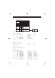
MU80 MIDI Data Format
2.1.4.4 Multi Effect1 Data parameter change
See Tables 1-1, 1-4.
2.1.4.5 Multi EQ Data parameter change
See Tables 1-1, 1-5.
2.1.4.6 Multi Effect2 Data parameter change
See Tables 1-1, 1-6.
2.1.4.7 Display Data parameter change
See Tables 1-1, 1-7.
2.1.4.8 Multi Part Data parameter change
See Tables 1-1, 1-8.
2.1.4.9 AD Part Data parameter change
See Tables 1-1, 1-9.
2.1.4.10 Drum Setup Data parameter change
See Tables 1-1, 1-10.
If operation is in XG mode, this message reinitializes all drum setup parameters.
Note that regardless of mode, drum setup parameters always reinitialize whenever the drum
set changes.
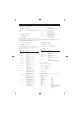
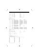
2.1.5 MU80 Native Parameter Change
11110000 F0 Exclusive status
01000011 43 YAMAHA ID
0001nnnn 1n Device Number
01001001 49 Model ID
0aaaaaaa aaaaaaa Address High
0aaaaaaa aaaaaaa Address Mid
0aaaaaaa aaaaaaa Address Low
0ddddddd ddddddd Data
||
11110111 F7 End of Exclusive
Data size must match parameter size (2 or 4 bytes).
2.1.5.1 MU80 System Data parameter change
See Tables 2-1, 2-2.
2.1.5.2 Current Performance parameter change
See Tables 2-1, 2-3.
2.1.5.3 Remote Switch
See Tables 2-1, 2-4.
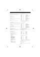
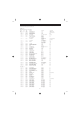
2.1.6 Other Parameter Changes
2.1.6.1 Master Tuning
11110000 F0 Exclusive status
01000011 43 YAMAHA ID
0001nnnn 1n Device Number
00100111 27 Model ID
00000001 30 Sub ID2
00000000 00
00000000 00
0mmmmmmm mm Master Tune MSB
0lllllll ll Master Tune LSB
0ccccccc cc
11110111 F7 End of Exclusive
Changes tuning of all channels.
2.2 Bulk Dump
The MU80 supports the following parameters.
[XG NATIVE ]
1) XG System Data
2) Multi Effect1 Data
3) Multi EQ Data
4) Multi Effect2 Data
5) Multi Part Data
6) AD Part Data
7) Drums Setup Data
[MU80 NATIVE ]
1) MU80 System data
2) Internal Performance
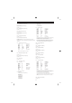
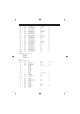
2.2.1 XG Native Bulk Data
11110000 F0 Exclusive status
01000011 43 YAMAHA ID
0000nnnn 0n Device Number
01001100 4C Model ID
0bbbbbbb bbbbbbb ByteCount
0bbbbbbb bbbbbbb ByteCount
0aaaaaaa aaaaaaa Address High
0aaaaaaa aaaaaaa Address Mid
0aaaaaaa aaaaaaa Address Low
00000000 00 Data
||
||
0ccccccc ccccccc Check sum
11110111 F7 End of Exclusive
For information about “Address” and “Byte Count” fields, refer to attached tables.
The checksum value is set such that the sum of Address, Byte Count, and
Checksum has value zero in its seven least significant bits.
No more than 512 bytes should be sent in a single transmission. If the Dump
Request asks for more than 512 bytes, data should be sent in packets of 512 bytes
or less, with at least 120ms between transmission of consecutive packets.
2.2.1.1 XG System Data bulk dump
See Tables 1-1, 1-2.
2.2.1.2 Multi Effect1 Data bulk dump
See Tables 1-1, 1-4.
2.2.1.3 Multi EQ Data bulk dump
See Tables 1-1, 1-5.
2.2.1.4 Multi Effect2 Data bulk dump
See Tables 1-1, 1-6.
2.2.1.5 Multi Part Data bulk dump
See Tables 1-1, 1-8.
2.2.1.6 AD Part Data bulk dump
See Tables 1-1, 1-9.
2.2.1.7 Drums Setup Data bulk dump
See Tables 1-1, 1-10.
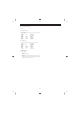
2.2.2 MU80 Native Bulk Dump
11110000 F0 Exclusive status
01000011 43 YAMAHA ID
0000nnnn 0n Device Number
01001001 49 Model ID
0bbbbbbb bbbbbbb ByteCount
0bbbbbbb bbbbbbb ByteCount
0aaaaaaa aaaaaaa Address High
0aaaaaaa aaaaaaa Address Mid
0aaaaaaa aaaaaaa Address Low
00000000 00 Data
||
||
0ccccccc ccccccc Check sum
11110111 F7 End of Exclusive
For information about “Address” and “Byte Count” fields, refer to attached tables.
The checksum value is set such that the sum of Address, Byte Count, and
Checksum has value zero in its seven least significant bits.
No more than 512 bytes should be sent in a single transmission.
If the Dump Request asks for more than 512 bytes, data should be sent in packets
of 512 bytes or less, with at least 120ms between transmission of consecutive
packets.
2.2.2.1 MU80 System Data bulk dump
See Tables 2-1, 2-2.