
User Guide


2
AC1
Parameter Range Value
Table No.
Control
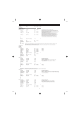
MU80 Effect Parameter List
HALL1,HALL2
ROOM1,ROOM2,ROOM3
STAGE1,STAGE2
PLATE
1 Reverb Time 0.3~30.0s 0-69 Table#4 This determines the time or length of the Reverb effect.
2 Diffusion 0~10 0-10 This determines the density and complexity of the reflections that make up the
Reverb effect. Lower values result in a clearer, simpler Reverb sound, while
higher values result in a thicker, richer sound.
3 Initial Delay 0~63 0-63 Table#5 This determines the time delay between the direct sound and the first of the many
reflections that make up the Reverb sound.
4 HPF Cutoff Thru~8.0kHz 0-52 Table#3 The High Pass Filter allows you to filter out low frequency sounds from the
Reverb sound, “passing” only the high frequencies above the cutoff point.
This parameter determines the frequency cutoff point for the filter.
Higher values effectively take the bass sounds out of the Reverb effect.
5 LPF Cutoff 1.0k~Thru 34-60 Table#3 The Low Pass Filter allows you to filter out high frequency sounds from the
Reverb sound, “passing” only the low frequencies below the cutoff point.
This parameter determines the frequency cutoff point for the filter.
Lower values effectively take the treble sounds out of the Reverb effect.
6
7
8
9
10 Dry/Wet D63>W ~ D=W ~ D<W63 1-127 •
11 Rev Delay 0~63 0-63 Table#5
12 Density 0~4 0-4
13 Er/Rev Balance E63>R ~ E=R ~ E<R63 1-127
14 High Damp 0.1~1.0 1-10
15
16
HINT : LPF Cutoff Judicious use of the Low Pass Filter helps to create a more natural Reverb sound, since many actual performance environments have a relatively “dead”
sound in which the high frequency reflections are absorbed. On the other hand, you may wish to create a more “live” reverb sound by setting the
High Pass Filter Cutoff above to emphasize the high frequencies.
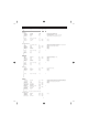
WHITE ROOM
TUNNEL
CANYON
BASEMENT
1 Reverb Time 0.3~30.0s 0-69 Table#4 See above.
2 Diffusion 0~10 0-10 See above.
3 Initial Delay 0~63 0-63 Table#5 See above.
4 HPF Cutoff Thru~8.0kHz 0-52 Table#3 See above.
5 LPF Cutoff 1.0k~Thru 34-60 Table#3 See above.
6 Width 0.5~10.2m 0-37 Table#11
7 Height 0.5~20.2m 0-73 Table#11
8 Depth 0.5~30.2m 0-104 Table#11
9 Wall Vary 0~30 0-30
10 Dry/Wet D63>W ~ D=W ~ D<W63 1-127
•
11 Rev Delay 0~63 0-63 Table#5
12 Density 0~4 0-4
13 Er/Rev Balance E63>R ~ E=R ~ E<R63 1-127
14 High Damp 0.1~1.0 1-10
15 Feedback Level -63~+63 1-127
16
DELAY L,C,R
1 Lch Delay 0.1~715.0ms 1-7150 Left channel initial delay time.
2 Rch Delay 0.1~715.0ms 1-7150 Right channel initial delay time.
3 Cch Delay 0.1~715.0ms 1-7150 Center channel initial delay time.
4 Feedback Delay 0.1~715.0ms 1-7150 Time delay of all delayed repeats following the initial delayed repeat.
5 Feedback Level -63~+63 1-127 Level of feedback delays.
A setting of 0 results in no delayed repeats after the initial delay.
6 Cch Level 0~127 0-127
7 High Damp 0.1~1.0 1-10
8
9
10 Dry/Wet D63>W ~ D=W ~ D<W63 1-127 •
11 HPF Cutoff Thru~8.0kHz 0-52 Table#3 See above.
12 LPF Cutoff 1.0k~Thru 34-60 Table#3 See above.
13
14
15
16
CAUTION! : FB Level Be careful when setting this parameter, since extreme values may result in uncontrollable feedback.
NOTE : FB Level This parameter is not available for the Symphonic effect.
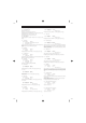
DELAY L,R
1 Lch Delay 0.1~715.0ms 1-7150 Right channel initial delay time.
2 Rch Delay 0.1~715.0ms 1-7150 Center channel initial delay time.
3 Feedback Delay 1 0.1~715.0ms 1-7150 Time delay of all delayed repeats (for Delay 1) following the initial delayed repeat.
4 Feedback Delay 2 0.1~715.0ms 1-7150 Time delay of all delayed repeats (for Delay 2) following the initial delayed repeat.
5 Feedback Level -63~+63 1-127 Level of both feedback delays.
6 High Damp 0.1~1.0 1-10
7
8
9
10 Dry/Wet D63>W ~ D=W ~ D<W63 1-127
•
11 HPF Cutoff Thru~8.0kHz 0-52 Table#3 See above.
12 LPF Cutoff 1.0k~Thru 34-60 Table#3 See above.
13
14
15
16
ECHO
1 Lch Delay1 0.1~355.0ms 1-3550 Left channel initial delay time.
2 Lch Feedback Level -63~+63 1-127 Level of left channel feedback delays (following initial delay).
3 Rch Delay1 0.1~355.0ms 1-3550 Right channel delay time.
4 Rch Feedback Level -63~+63 1-127 Level of right channel feedback delays (following initial delay).
5 High Damp 0.1~1.0 1-10 Damping or filtering out of high frequencies in delay sound.
6 Lch Delay2 0.1~355.0ms 1-3550
7 Rch Delay2 0.1~355.0ms 1-3550
8 Delay2 Level 0~127 0-127
9
10 Dry/Wet D63>W ~ D=W ~ D<W63 1-127 •
11 HPF Cutoff Thru~8.0kHz 0-52 Table#3 See above.
12 LPF Cutoff 1.0k~Thru 34-60 Table#3 See above.
13