
User Guide


3
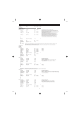
MU80 Effect Parameter List
AC1
Parameter Range Value
Table No.
Control
14
15
16
CROSS DELAY
1 L->R Delay 0.1~355.0ms 1-3550 Time of delay fed from left channel to right.
2 R->L Delay 0.1~355.0ms 1-3550 Time of delay fed from right channel to left.
3 Feedback Level -63~+63 1-127 Level of feedback delays.
4 Input Select L,R,L&R 0-2 Determines input for initial delay: Left, Right, or Left & Right.
5 High Damp 0.1~1.0 1-10 Damping or filtering out of high frequencies in delay sound.
6
7
8
9
10 Dry/Wet D63>W ~ D=W ~ D<W63 1-127 •
11 HPF Cutoff Thru~8.0kHz 0-52 Table#3 See above.
12 LPF Cutoff 1.0k~Thru 34-60 Table#3 See above.
13
14
15
16
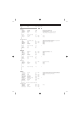
EARLY REF1,EARLY REF2
1 Type S-H, L-H, Rdm, Rvs, Plt, Spr 0-5 Selects the pattern of early reflections: S-H (Small Hall), L-H (Large Hall), Rdm
(Random), Rvs (Reverse), Plt (Plate), Spr (Spring).
2 Room Size 0.1~7.0 0-44 Table#6 Apparent room size. Affects length of reflections.
3 Diffusion 0~10 0-10 See above.
4 Initial Delay 0~63 0-63 Table#5 See above.
5 Feedback Level -63~+63 1-127 See above.
6 HPF Cutoff Thru~8.0kHz 0-52 See above.
7 LPF Cutoff 1.0k~Thru 34-60 See above.
8
9
10 Dry/Wet D63>W ~ D=W ~ D<W63 1-127
•
11 Liveness 0~10 0-10
12 Density 0~3 0-3
13 High Damp 0.1~1.0 1-10
14
15
16
GATE REVERB
REVERSE GATE
1 Type TypeA,TypeB 0-1 Selects the type of gate reverb.
2 Room Size 0.1~7.0 0-44 Table#6 Apparent room size. Affects length of reverb.
3 Diffusion 0~10 0-10 See above.
4 Initial Delay 0~63 0-63 Table#5 See above.
5 Feedback Level -63~+63 1-127 See above.
6 HPF Cutoff Thru~8.0kHz 0-52 See above.
7 LPF Cutoff 1.0k~Thru 34-60 See above.
8
9
10 Dry/Wet D63>W ~ D=W ~ D<W63 1-127
•
11 Liveness 0~10 0-10
12 Density 0~3 0-3
13 High Damp 0.1~1.0 1-10
14
15
16
KARAOKE1,2,3
1 Delay Time 0~63 0-127 Table#7 Time between delayed repeats.
2 Feedback Level -63~+63 1-127 See above.
3 HPF Cutoff Thru~8.0kHz 0-52 See above.
4 LPF Cutoff 1.0k~Thru 34-60 See above.
5
6
7
8
9
10 Dry/Wet D63>W ~ D=W ~ D<W63 1-127
•
11
12
13
14
15
16
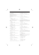
CHORUS1,2,3
CELESTE1,2,3
1 LFO Frequency 0.08~39.7Hz 0-127 Table#1 This determines the amount of phase shift, or to what degree the modulated signal
is out of phase with the dry signal. Lower values result in the signal being more
out of phase, and hence create a stronger Phaser effect.
2 LFO PM Depth 0~63 0-63 See above.
3 Feedback Level -63~+63 1-127 See above.
4 Delay Offset 0~127 0-127 Table#2 See above.
5
6 EQ Low Frequency 32Hz~2.0kHz 4-40 Table#3
7 EQ Low Gain -12~+12dB 52-76
8 EQ High Frequency 500Hz~16.0kHz 28-58 Table#3
9 EQ High Gain -12~+12dB 52-76
10 Dry/Wet D63>W ~ D=W ~ D<W63 1-127
•
11 EQ Mid Frequency 100Hz~10.0kHz 14-54 Table#3
12 EQ Mid Gain -12~+12dB 52-76
13 EQ Mid Width 1.0~12.0 10-120
14 LFO AM Depth 0~127 0-127
15
16
NOTE : Delay Ofst This parameter is not available for the Phaser effect.
FLANGER1,FLANGER2
1 LFO Frequency 0.08~39.7Hz 0-127 Table#1 See above.
2 LFO Depth 0~127 0-127
3 Feedback Level -63~+63 1-127
4 Delay Offset 0~63 0-63 Table#2
5
6 EQ Low Frequency 32Hz~2.0kHz 4-40 Table#3