AD CONVERTER Owner’s Manual POWER ON OFF E
FCC INFORMATION (U.S.A.) 1. IMPORTANT NOTICE: DO NOT MODIFY THIS UNIT! This product, when installed as indicated in the instructions contained in this manual, meets FCC requirements. Modifications not expressly approved by Yamaha may void your authority, granted by the FCC, to use the product. 2. IMPORTANT: When connecting this product to accessories and/or another product use only high quality shielded cables. Cable/s supplied with this product MUST be used. Follow all installation instructions.
i Important Information Please read the following before using the AD824 Warnings • Do not subject the AD824 to extreme temperatures, humidity, direct sunlight, or dust, which could be a potential fire or electrical shock hazard. • Do not allow water to enter the AD824 or allow it to become wet. Fire or electrical shock may result. • Connect the power cord only to an AC outlet of the type stated in this Owner’s Manual or as marked on the AD824. Failure to do so is a fire and electrical shock hazard.
ii Cautions • Allow enough free space around the unit for normal ventilation. This should be: 10 cm at the sides, 15 cm behind, and 30 cm above. These distances should also be adopted when rack-mounting the AD824. For normal ventilation during use, remove the rear of the rack or open a ventilation hole. If the airflow is not adequate, the AD824 will heat up inside and may cause a fire. • Use the AD824 in an environment with a temperature of between 10˚C and 35˚C (50˚F and 95˚F).
iii Trademarks ADAT MultiChannel Optical Digital Interface is a trademark of Alesis Corporation. Tascam Digital Interface is a trademark and Tascam and Teac are registered trademarks of Teac Corporation. Yamaha is a trademark of Yamaha Corporation. All other trademarks are the property of their respective holders and are hereby acknowledged.
iv Contents Contents 1 Introduction . . . . . . . . . . . . . . . . . . . . . . . . . . . . . . . . 1 Welcome . . . . . . . . . . . . . . . . . . . . . . . . . . . . . . . . . . . . . . . . . . . . . . . . . . . . . . . . . . . Installation . . . . . . . . . . . . . . . . . . . . . . . . . . . . . . . . . . . . . . . . . . . . . . . . . . . . . . . . . Connecting the Power Cord . . . . . . . . . . . . . . . . . . . . . . . . . . . . . . . . . . . . . . . . . . . Turning On the Power . . . . . . . . . . .
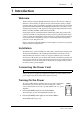
Introduction 1 1 Introduction Welcome Thank you for choosing the Yamaha AD824 AD Converter. The AD824 is a high-performance 8-channel analog-to-digital converter, with 24-bit linear analog-to-digital converters and 128-times oversampling, providing a typical dynamic range of 110 dB. Optional mini YGDAI (Yamaha General Digital Audio Interface) cards offer a variety of digital output interfaces, with support for all the popular digital audio interconnect formats, including AES/EBU, ADAT, and Tascam TDIF-1.
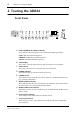
2 Chapter 2—Touring the AD824 2 Touring the AD824 Front Panel WORD CLOCK INTERNAL 44.1kHz 48kHz BNC PEAK PEAK NOMINAL SLOT NOMINAL SIGNAL GAIN POWER ON OFF dB SIGNAL +48V +48V 1 2 3 4 5 6 7 SEL +48V MASTER OFF ON 8 SEL AD CONVERTER A PEAK, NOMINAL & SIGNAL indicators These indicators show the signal level of each channel and light up as follows: PEAK 3 dB below maximum input level. NOMINAL 14 dB below maximum input level. SIGNAL 34 dB below maximum input level.
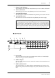
3 Rear Panel J Channel +48V indicators These indicators show whether the +48V phantom power is on or off for each channel. K +48V on/off button This button is used to set the +48V phantom power for the selected channel. L +48V MASTER indicator This indicator shows whether the MASTER +48V phantom power switch is on or off. M +48V MASTER switch This switch is used to turn on and off the +48V phantom power master supply.
4 Chapter 2—Touring the AD824 D COM PC/RS422 port This 9-pin D-sub connector is for connecting the AD824 to a device for remote control, such as a Yamaha DME32 or personal computer. It’s also used to connect to the previous AD824 in a multiple-unit system.
Operation 5 3 Operation Selecting the Wordclock Source The wordclock source can be set to 44.1 kHz internal, 48 kHz internal, BNC, or SLOT. Note: When the wordclock source is changed on the wordclock master device (e.g., this AD824, a DME32 or 02R), noise may occur from the outputs of the wordclock slave devices, especially a AD824 with an MY8-AT I/O card installed, so turn down your power amps beforehand, otherwise any connected speakers may be damaged. 1 Use the [WORD CLOCK] button to select a source.
6 Chapter 3—Operation Setting the +48V Phantom Power Master The +48V phantom power for all channels can be turned on and off by using the +48V MASTER switch. 1 Set the +48V MASTER switch to the ON position to turn on the +48V phantom power master supply. The +48V MASTER indicator lights up. 2 Set the +48V MASTER switch to the OFF position to turn off the +48V phantom power master supply. The +48V MASTER indicator goes out.
Digital I/O Cards 7 4 Digital I/O Cards About Digital I/O Cards For digital output the AD824 uses optional mini YGDAI (Yamaha General Digital Audio Interface) cards, which are available in all the popular digital audio interconnect formats, including AES/EBU, ADAT, and Tascam TDIF-1. The following digital I/O cards are currently available. See the Yamaha Professional Audio Web site at the following address for up-to-date news on mini YGDAI cards: .
8 Chapter 4—Digital I/O Cards Installing I/O Cards This section explains how to install mini YGDAI cards in the AD824. 1 Turn off the AD824. 2 Undo the two fixing screws and remove the slot cover, as shown below. CO M PC RS 42 2 OU T W OR D SL OT CL OC K 7 ON 5Ω OF F IN 8 8 8 Keep the cover and fixing screws in a safe place for future use. 3 Insert the card between the guide rails and slide it all the way into the slot, as shown below.
9 Hookup Examples 5 Hookup Examples In the following hookup examples, the “digital audio device” could be any device with a compatible AES/EBU or ADAT interface, including the following Yamaha products with the necessary I/O cards installed: DME32 Digital Mixing Engine, 02R Digital Recording Console, 03D Digital Mixing Console, 01V Digital Mixing Console, or D24 Digital Multitrack Recorder.
10 Chapter 5—Hookup Examples AES/EBU Connection with Splitter Cable This example shows how both an AD824 and DA824 can be connected to a digital audio device with a single AES/EBU interface by using MY8-AE I/O cards and a custom AES/EBU splitter cable. Pin wiring details for the AES/EBU interface are supplied with the MY8-AE I/O card. The digital audio device is the wordclock master, with the AD824 receiving its wordclock via a BNC connection, the DA824, via its slot input.
11 Insert Connection Insert Connection This example shows how analog outboard equipment can be patched into each channel by using the INSERT IN and OUT 1/4" TRS phone jacks. The insert point on each channel is located between the head amplifier and A/D converter. The signal level indicators are located after the INSERT IN connector. Digital Audio Device (DME32, 02R, D24, etc.) AES/EBU I/O AES/EBU cable SLOT: MY8-AE AD824 Outboard equipment Input OUT INSERT WORD CLOCK INTERNAL 44.
12 Chapter 5—Hookup Examples
Multiple AD824 Connection 13 Multiple AD824 Connection The next example shows how the AD824 COM ports can be used to connect several AD824s in combination with a DME32. The COM PC/RS422 port on the AD824 #1 is connected to the COM port on the DME32, while the COM RS422 port on AD824 #1 is connected to the COM PC/RS422 port on AD824 #2. The COM PC/RS422 switches on both AD824s are set to RS422. The DME32 is the wordclock master and both the AD824s receive their wordclocks via their SLOT inputs.
14 Chapter 6—Wordclocks 6 Wordclocks About Wordclocks For correct operation and analog-to-digital conversion, it’s essential that the AD824 is wordclock locked to the digital audio device connected to its SLOT output. The AD824 can generate a wordclock signal internally at either 44.1 kHz or 48 kHz, so it could be used as the wordclock master, in which case the device connected to the SLOT would be used as a wordclock slave.
Wordclock Termination 15 Wordclock Termination For correct and reliable operation, wordclock signals distributed via BNC cables must be terminated correctly. Termination is typically applied at the last device, although it depends on the distribution method being used. The AD824’s WORD CLOCK 75Ω ON/OFF switch allows the AD824 to be connected in a variety of ways. The following examples show three ways in which wordclock signals can be distributed and how termination should be applied in each case.
16 Appendix Appendix Error Messages The AD824 performs several diagnostic checks when it’s turned on. If a problem is detected, one of the following error codes appears briefly on the GAIN display. E1—Internal backup-battery voltage low. E2—Internal memory data corrupt. E3—Internal backup-battery voltage low and internal memory data corrupt. Specifications MY8-AE, MY8-TD 39.69–50.88 kHz MY8-AT 41.013–50.88 kHz Sampling rate AD conversion resolution 24-bit linear, 128-times oversampling –1.
Specifications 17 Power requirements U.S.A. & Canada 120 V AC, 60 Hz Europe 230 V AC, 50 Hz Power consumption 50 W Dimensions (W × H × D) 480 × 97.5 × 377.6 mm (18.9 x 3.84 x 14.86 inches) Weight 8.5 kg (18.7 lbs) Free-air operating temperature 10˚ C to 35˚ C (50˚ F to 95˚ F) Storage temperature –20˚ C to 60˚ C (–4˚ F to 140˚ F) Relative humidity 10%–95% Power cord length 1.9 m Supplied accessories Owner’s Manual, 9-pin D-sub crossed cable (1.
18 Appendix Digital I/O Connection Format Level/Impedance Connector COM PC/RS422 — RS232C/RS422 9-pin D-sub (male) COM RS422 — RS422 9-pin D-sub WORD CLOCK IN — TTL, 75Ω (ON/OFF) BNC — TTL, 75Ω BNC mini YGDAI — — WORD CLOCK OUT SLOT Dimensions 30 10.8 48 30 274 D: 377.6 355 (33) 13 430 W: 480 410 35 H: 97.5 45 17 35 88 67.5 345 67.5 Specifications and external appearance subject to change without notice.