AV Pre-Amplifier Owner’s Manual Read the supplied booklet “Safety Brochure” before using the unit.
CONTENTS Accessories . . . . . . . . . . . . . . . . . . . . . . . . . . . . . . . . . . . . . . . . . . . . . . . . . . . . . . 5 7 Connecting other devices . . . . . . . . . . . . . . . . . . . . . . . . . . . . . . . . . . . . . . 41 Connecting a device with analog multichannel output . . . . . . . . . . . . . . . . . . . . . . . . . . . . . . . . . . . . . . . . . . . . . 41 FEATURES 6 Connecting a device compatible with the trigger function . . . . . . . . . . . . . . . . . . . . . . . . . . . . .
CONFIGURATIONS Listening to FM/AM radio . . . . . . . . . . . . . . . . . . . . . . . . . . . . . . . . . . . . . . . 75 Setting the frequency steps . . . . . . . . . . . . . . . . . . . . . . . . . . . . . . . . . . . . . . . . . . . . . . . . . . . . . . . . . . . . . . . . . . . . . . . 75 Selecting a frequency for reception . . . . . . . . . . . . . . . . . . . . . . . . . . . . . . . . . . . . . . . . . . . . . . . . . . . . . . . . . . . . . . . . 75 112 Configuring input sources (Input menu) . . .
Controlling external devices with the remote control . . . . . . . . . . . . . 149 Reference diagram (rear panel) . . . . . . . . . . . . . . . . . . . . . . . . . . . . . . . . . 180 Registering remote control codes . . . . . . . . . . . . . . . . . . . . . . . . . . . . . . . . . . . . . . . . . . . . . . . . . . . . . . . . . . . . . . . . . 150 Trademarks . . . . . . . . . . . . . . . . . . . . . . . . . . . . . . . . . . . . . . . . . . . . . . . . . . .
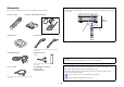
Accessories Operating range of the remote control Check that the following accessories are supplied with the product. • Point the remote control at the remote control sensor on the unit and remain within the operating range shown below. Remote control Batteries (AAA, LR03, UM-4) (x4) Within 6 m (20 ft) 30° 30° Insert the batteries the right way round. AM antenna FM antenna *One of the above is supplied depending on the region of purchase.
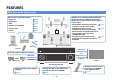
FEATURES What you can do with the unit Wide variety of supported content • Bluetooth • iPod/iPhone • USB • Media server (PC/NAS) • Internet radio • AirPlay . . . . . . Supports 2- to 11-channel balance/unbalance pre-out and up to 2 subwoofer connections. Allows you to enjoy favorite acoustic spaces in various styles. p.79 p.80 p.84 p.87 p.91 p.94 • Automatically optimizing the speaker . p.45 settings to suit your room (YPAO) • Reproducing stereo or latest . p.
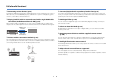
Full of useful functions! ❑ Connecting various devices (p.35) ❑ Surround playback with 5 speakers placed in front (p.72) A number of HDMI jacks and various input/output jacks on the unit allow you to connect video devices (such as BD/DVD players), audio devices (such as CD players), game consoles, camcorders, and other devices.
Useful tips I want to connect a playback device using HDMI for video and non-HDMI for audio... Use “Audio Select” in the “Option” menu to specify the type of an audio input jack to be used for the corresponding input source (p.111). Video and audio are not synchronized... Use “Lipsync” in the “Setup” menu to adjust the delay between video and audio output (p.128). I want to hear audio from the TV speakers...
CINEMA DSP The excitement of a concert hall and the powerful sense of being inside a movie - we all want to enjoy these experiences in our own living room. Yamaha has pursued the fulfillment of these desires for more than 20 years, and this fulfillment has now taken shape as the Yamaha AV receivers.
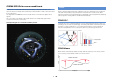
CINEMA DSP HD3 for new surround format YPAO In 2014, the new surround audio format that employs “object-based audio” was announced (such as Dolby Atmos). With object-based audio, sounds can be allocated freely in 3D space. YPAO is Yamaha original automatic calibration system to optimizing your sound and surround environment by using microphone measurement.
YPAO 3D measurement Unrivaled audio and video quality The direction (angle) of front, surround and presence speakers, and the height of presence speakers as seen from the listening position is measured, and compensation is applied to maximize the 3D sound field effectiveness of the CINEMA DSP. High-resolution music enhancer 32-bit Hi-bit high-sampling extension up to 96 kHz / 32-bit can be applied to lossless 44.
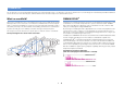
Expandable to meet diverse needs The best expandability in Yamaha Multi-zone function Useful applications By connecting a power amplifier, you can enjoy the highest peak of CINEMA DSP - an 11.2-channel 3-dimensional sound field. The multi-zone function (p.96) allows you to play back different input sources in the room where the unit is installed (main zone) and in other rooms (such as Zone2). ■ AV CONTROLLER Power amplifier (The following shows examples of use.
Part names and functions Front panel 1 2 3 4 5 MAIN ZONE PURE DIRECT VOLUME INPUT ON SCREEN OPTION SCENE TONE/BALANCE STRAIGHT 1 2 ZONE 2 ZONE 3 3 MULTI ZONE PROGRAM INFO (WPS) MEMORY PRESET FM AM TUNING 4 ENTER RETURN ZONE 4 VIDEO AUX PHONES 5V 6 1 MAIN ZONE z key Turns on/off (standby) the unit. 2 Standby indicator Lights up when the unit is in standby mode under any of the following conditions. • HDMI Control is enabled (p.133) • Standby Through is enabled (p.
■ Inside of the front panel door 9 0 AB C ON SCREEN OPTION DE F GH SCENE TONE/BALANCE STRAIGHT 1 2 3 IJ K INFO (WPS) MEMORY PRESET FM AM TUNING L 4 (CONNECT) MULTI ZONE PROGRAM ENTER ZONE 2 RETURN ZONE 3 ZONE 4 VIDEO AUX PHONES 5V 1A M 9 ON SCREEN key Displays the on-screen menu on the TV. 0 Menu operations keys Cursor keys Select a menu or a parameter. ENTER Confirms a selected item. RETURN Returns to the previous screen. A OPTION key Displays the option menu (p.107).
Front display (indicators) 1 2 5 4 3 A Lights up when HDMI signals are being input or output. IN Lights up when HDMI signals are being input. OUT1/OUT2 Indicates the HDMI OUT jacks currently outputting an HDMI signal. 2 Signal strength indicator Indicates the strength of the wireless network signal (p.57). 3 ZONE indicators Lights up when Zone2, Zone3 or Zone4 is enabled (p.100). 4 SLEEP Lights up when the sleep timer is on.
Rear panel 1 2 3 4 5 6 7 8 9 0 A B C D (U.S.A. model) DC OUT 5V 0.5A NETWORK HDMI (HDCP2.2) HDMI OUT ( 3 NET ) (HDCP2.
(U.S.A. model) DC OUT 5V 0.5A NETWORK HDMI (HDCP2.2) HDMI OUT ( 3 NET ) (HDCP2.
Remote control 1 Remote control signal transmitter 1 Transmits infrared signals. 2 2 RECEIVER z key SOURCE RECEIVER Turns on/off (standby) the unit. SOURCE/RECEIVER key 3 Changes the device (the unit or external device) that is operated with the remote control (p.152). You can operate the unit when this key lights up in orange, and an external device when this key lights up in green.
■ Inside of the remote control cover I Sound mode keys Select a sound mode (p.69). SOURCE RECEIVER J INFO key Selects the information displayed on the front display (p.106). K Numeric keys AV 1 2 5 6 3 4 7 V-AUX Let you enter numerical values, such as radio frequencies. L ZONE key AUDIO 1 2 3 4 TUNER BLUETOOTH USB NET PHONO MULTI [A] [B] Changes the zone that is controlled by the remote control (p.100). M PARTY key Turns on/off the party mode (p.101).
PREPARATIONS General setup procedure 1 Placing speakers (p.21) Select the speaker layout and connect the speakers to the power amplifier. For details on speaker connections, refer to the instruction manual for the power amplifier. 2 Connecting the power amplifier and subwoofers (p.30) Connecting the power amplifier and subwoofers (with built-in amplifier) to the unit. 3 Connecting a TV (p.33) Connect a TV to the unit. 4 Connecting playback devices (p.
1 2 3 4 5 6 7 8 9 10 11 12 1 Placing speakers The unit has 11.2-channel pre-amplifiers. You can connect 2- to 11-channel speakers (via a power amplifier) and up to 2 subwoofers to create the favorite acoustic space in your room. You can also apply multi-zone configurations to enhance your system (p.96). Ideal speaker layout Functions of each speaker Speaker type Abbr. Function Front (L) 1 Front (R) 2 Center 3 Produces center channel sounds (such as movie dialogues and vocals).
1 2 3 4 5 6 7 8 9 10 11 12 Basic speaker configuration ■ Placing speakers in your room Depending on the number of speakers, place the speakers and subwoofer in your room. This section describes the representative speaker layout examples. ❑ 9.2-channel system [★5.1.4] (using rear presence speakers) • To play back Dolby Atmos contents, apply a speaker system with a ★ mark. E • (About the number of channels) For example, “5.1.2” denotes “standard 5.1-channel plus 2 for overhead speaker channels”.
1 2 3 4 5 6 7 8 9 10 11 12 ❑ 9.2-channel system [★7.1.2] (using surround back speakers) E ❑ 7.1-channel system [★5.1.2] (using front presence speakers) R 1 9 2 3 9 4 5 6 7 This speaker system uses the front presence speakers to produce a natural 3-dimensional sound field, and also allows you to enjoy extended surround sounds using the surround back speakers.
1 2 3 4 5 6 7 8 9 10 11 12 ❑ 7.1-channel system [★7.1.0] (using surround back speakers) ❑ 5.1-channel system This speaker system creates front Virtual Presence Speaker (VPS) using the front, center and surround speakers to produce a 3-dimensional sound field, and also allows you to enjoy extended surround sounds using the surround back speakers.
1 2 3 4 5 6 7 8 9 10 11 12 ❑ Front 5.1-channel system (using surround speakers) 4 ❑ Front 5.1-channel system (using front presence speakers) 5 9 Even when surround speakers are placed in the front side, the unit creates the virtual surround speakers in the rear side to allow you to enjoy multichannel surround sound (Virtual CINEMA FRONT) when “Layout (Surround)” (p.126) in the “Setup” menu is set to “Front”.
1 2 3 4 5 6 7 8 9 10 11 12 ❑ 2.1-channel system ❑ Presence speaker layout The unit provides three layout patterns for presence speakers (Front Height/Rear Height, Overhead and Dolby Enabled SP). Choose a layout pattern that suits your listening environment. • You can enjoy Dolby Atmos or Cinema DSP HD3 with any layout pattern. • You can configure the placement patterns for front presence and rear presence speakers separately.
1 2 3 4 5 6 7 8 9 10 11 12 Dolby Enabled SP Notes on installation of ceiling speakers Use the Dolby Enabled speakers as the presence speakers. When installing presence speakers to a ceiling, use the following illustration as a reference. It utilizes sounds reflected from ceiling and lets you enjoy overhead sounds only from speakers that are placed at the same level as traditional speakers.
Input/output jacks and cables ■ Video/audio jacks ■ Video jacks ❑ HDMI jacks ❑ COMPONENT VIDEO jacks Transmit digital video and digital sound through a single jack. Use an HDMI cable. Transmit video signals separated into three components: luminance (Y), chrominance blue (PB), and chrominance red (PR). Use a component video cable with three plugs. AV 1 HDMI cable Component video cable A Y • Use a 19-pin HDMI cable with the HDMI logo. We recommend using a cable less than 5.0 m (16.
■ Audio jacks ❑ XLR jacks ❑ OPTICAL jacks Transmit analog audio signals. Use an XLR balanced cable. Transmit digital audio signals. Use a digital optical cable. Remove the tip protector (if available) before using the cable. About the XLR jacks XLR input jacks Match the pins and insert the “male” connector of the XLR balanced cable until you hear a click. Digital optical cable XLR balanced cable (male) IO AUD 4 R Transmit digital audio signals. Use a digital coaxial cable.
1 2 3 4 5 6 7 8 9 10 11 12 2 Connecting the power amplifier and subwoofers ■ Balanced connection Connecting a power amplifier Depending on the speaker system you want to use, connect the corresponding PRE OUT (XLR) jacks of the unit to the amplifier with XLR balanced cables. Connect the input jacks of your power amplifier to the PRE OUT jacks of the unit so that the audio source selected on the unit can be output to the power amplifier for playback.
1 2 3 4 5 6 7 8 9 10 11 12 ■ Unbalanced connection Connecting subwoofers Depending on the speaker system you want to use, connect the corresponding PRE OUT (RCA) jacks of the unit to the amplifier with audio pin cables (RCA unbalanced cables). Connect the subwoofers (with built-in amplifier) to the PRE OUT jacks of the unit. Select a balanced (XLR) or an unbalanced (RCA) connection depending on the input jacks available on your subwoofer.
1 2 3 4 5 6 7 8 9 10 11 12 ■ Unbalanced connection Connect the subwoofers (with built-in amplifier) to the SUBWOOFER PREOUT (RCA) 1–2 jacks of the unit with audio pin cables (RCA unbalanced cables). The unit (rear) HDMI (HDCP2.
1 2 3 4 5 6 7 8 9 10 11 12 3 Connecting a TV Connect a TV to the unit so that video input to the unit can be output to the TV. To use HDMI Control and ARC, you need to configure the HDMI settings on the unit. For details on the settings, see “Information on HDMI” (p.177). You can also enjoy playback of TV audio on the unit. To maximize the performance of the unit, we recommend connecting a TV with an HDMI cable. About Audio Return Channel (ARC) • ARC allows audio signals to travel both ways.
1 2 3 4 5 6 7 8 9 10 11 12 ■ Connecting another TV or a projector ❑ COMPONENT VIDEO connection (with a component video cable) The unit (rear) MONITOR OUT/ ZONE OUT (HDCP2.2) (ZONE OUT) AV 1 (1 BD/DVD) CENTER L AV 1 1 AV 3 AV 2 AV 3 Video input (component video) AV 4 (1 BD/DVD) ARC AV 2 AV 4 MONITOR OUT/ ZONE OUT PB Y The unit has two HDMI output jacks.
1 2 3 4 5 6 7 8 9 10 11 12 4 Connecting playback devices Connecting video devices (such as BD/DVD players) The unit is equipped with a variety of input jacks including HDMI input jacks to allow you to connect different types of playback devices. For information on how to connect an iPod or a USB storage device, see the following pages. Connect video devices such as BD/DVD players, set-top boxes (STBs) and game consoles to the unit.
1 2 3 4 5 6 7 8 9 10 11 12 ■ Component video connection ■ Composite video connection Connect a video device to the unit with a component video cable and an audio cable (digital coaxial, digital optical or stereo pin cable). Choose a set of input jacks (on the unit) depending on the audio output jacks available on your video device. Connect a video device to the unit with a video pin cable and an audio cable (digital coaxial, digital optical, or stereo pin cable).
1 2 3 4 5 6 7 8 9 10 11 12 Connecting audio devices (such as CD players) Audio output (PHONO) PHONO jacks Connect audio devices such as CD players, MD players, and a turntable to the unit. Depending on the audio output jacks available on your audio device, choose one of the following connections. PHONO PHONO L L L L R R The unit (rear) R HDMI OUT (HDCP2.2) 2 1 (ZONE OUT) GND • The following explanation is based on the assumption that you have not changed the “Input Assignment” setting (p.
1 2 3 4 5 6 7 8 9 10 11 12 Connecting to the jacks on the front panel ❑ Composite video/analog stereo connection Use the VIDEO AUX jack to temporarily connect a playback device to the unit. Connect a playback device (such as game consoles and camcorders) to the unit with a video pin cable and a stereo pin cable. Use the USB jack to connect an iPod or a USB storage device. For details, see “Connecting an iPod” (p.80) or “Connecting a USB storage device” (p.84).
1 2 3 4 5 6 7 8 9 10 11 12 5 Connecting the FM/AM antennas Connect the supplied FM/AM antennas to the unit. Assembling the AM antenna Fix the end of the FM antenna to a wall, and place the AM antenna on a flat surface. FM antenna AM antenna HDMI (HDCP2.2) HDMI OUT (HDCP2.
1 2 3 4 5 6 7 8 9 10 11 12 6 Connecting a network cable or preparing the wireless antenna Connect the unit to a router (access point) with a network cable, or prepare the wireless antenna for establishing a wireless network connection. You can enjoy Internet radio or music files stored on media servers, such as PCs and Network Attached Storage (NAS), on the unit.
1 2 3 4 5 6 7 8 9 10 11 12 7 Connecting other devices Connecting a device with analog multichannel output Connecting a device compatible with the trigger function You can connect an analog multichannel output device such as a DVD player and an SACD player to the MULTI CH INPUT jacks. The trigger function can control an external device in conjunction with operating the unit (such as powering on/off and input selection).
1 2 3 4 5 6 7 8 9 10 11 12 8 Connecting the power cable After all the connections are complete, connect the supplied power cable to the unit and then to an AC wall outlet.
1 2 3 4 5 6 7 8 9 10 11 12 SOURCE RECEIVER RECEIVER z Select the desired on-screen menu language from English, Japanese, French, German, Spanish, Russian, Italian and Chinese. AV 1 2 3 4 5 6 7 V-AUX 1 2 AUDIO 1 2 3 4 TUNER BLUETOOTH USB NET PHONO MULTI [A] [B] 9 Selecting an on-screen menu language SCENE 1 2 3 PROGRAM MUTE 4 Turn on the TV and switch the TV input to display video from the unit.
1 2 3 4 5 6 7 8 9 10 11 12 SOURCE RECEIVER RECEIVER z If you use any of the following speaker configurations, follow the procedure below to configure the corresponding speaker settings manually before performing YPAO. AV 1 2 3 4 5 6 7 V-AUX 1 2 3 4 TUNER BLUETOOTH USB NET PHONO MULTI [A] [B] 10 Configuring the necessary speaker settings AUDIO 6 When using the surround speakers for front 5.1-channel system (Virtual CINEMA FRONT) • Using the surround speakers for front 5.
1 2 3 4 5 6 7 8 9 10 11 12 SOURCE RECEIVER RECEIVER z The Yamaha Parametric room Acoustic Optimizer (YPAO) function detects speaker connections, measures the distances from them to your listening position(s), and then automatically optimizes the speaker settings, such as volume balance and acoustic parameters, to suit your room.
1 2 3 4 5 6 7 8 9 10 11 12 ❑ Multi Position The following screen appears on the TV. SOURCE RECEIVER SOURCE/RECEIVER Selects multi measure or single measure. AV 1 2 3 4 5 6 7 V-AUX AUDIO 1 2 3 4 TUNER BLUETOOTH USB NET PHONO MULTI [A] [B] SCENE 1 2 3 PROGRAM MUTE 4 VOLUME • To cancel the operation, disconnect the YPAO microphone before starting the measurement.
1 2 3 4 5 6 7 8 9 10 11 12 Single measure a ❑ Angle/Height Multi measure (5 listening positions) d Enables/disables the angle/height measurement. e bac Settings Multi measure Multi measure (1 listening position + front/back/left/right) (2 listening positions + front/back) b c a e d c a b d En 47 Yes Enables the angle/height measurement.
1 2 3 4 5 6 7 8 9 10 11 12 Measuring at one listening position (single measure) SOURCE RECEIVER 2 3 4 5 6 7 V-AUX AUDIO 1 2 3 4 TUNER BLUETOOTH USB NET PHONO MULTI [A] [B] • If any error message (such as E-1) or warning message (such as W-1) appears, see “Error messages” (p.55) or “Warning messages” (p.56). SCENE 1 2 3 Proceed to Step 2. When “Multi Position” is set to “No”, follow the procedure below for measurement. It takes about 5 minutes to perform the measurement.
1 2 3 4 5 6 7 8 9 10 11 12 c Place the microphone base at the listening position and set the YPAO microphone to the position “1”. SOURCE RECEIVER e In the same way, perform the angle measurement for the positions “2” and “3”. f Set the YPAO microphone at the top of the pole and perform the fourth angle measurement.
1 2 3 4 5 6 7 8 9 10 11 12 4 SOURCE RECEIVER To save the measurement results, use the cursor keys (e/r) to select “SAVE” and press ENTER. 6 Disconnect the YPAO microphone from the unit. This completes optimization of the speaker settings.
1 2 3 4 5 6 7 8 9 10 11 12 Measuring at multiple listening positions (multi measure) SOURCE RECEIVER When “Multi Position” is set to “Yes”, follow the procedure below for measurement. It takes about 15 minutes to measure 8 listening positions. AV 1 2 3 4 5 6 7 V-AUX AUDIO 1 2 3 4 TUNER BLUETOOTH USB NET PHONO MULTI [A] [B] 1 2 When the measurements at the positions you want to measure are completed, use the cursor keys to select “CANCEL” and press ENTER.
1 2 3 4 5 6 7 8 9 10 11 12 4 SOURCE RECEIVER d Press ENTER to start the first angle measurement. Perform the angle/height measurement. a Use the cursor keys to select “YES” and press ENTER. Select “NO” to cancel the angle/height measurement. AV 1 2 5 6 1 2 TUNER PHONO The following screen appears on the TV when the first angle measurement finishes. 3 4 7 V-AUX 3 4 BLUETOOTH USB NET MULTI [A] [B] b Attach the supplied pole to the center of the microphone base.
1 2 3 4 5 6 7 8 9 10 11 12 5 SOURCE RECEIVER Use the cursor keys to select “Save/Cancel” and press ENTER. 8 Disconnect the YPAO microphone from the unit. This completes optimization of the speaker settings. AV 1 2 3 4 5 6 7 V-AUX • To check the measurement results, select “Result”. For details, see “Checking the measurement results” (p.53).
1 2 3 4 5 6 7 8 9 10 11 12 2 SOURCE RECEIVER AV 1 2 3 4 5 6 7 V-AUX Use the cursor keys to select an item. Wiring Polarity of each speaker Reverse: The speaker cable may be connected with the reverse polarity (+/-). Size Size of each speaker (cross-over frequency of the subwoofer) Large: The speaker can reproduce low-frequency signals effectively. Small: The speaker cannot reproduce low-frequency signals effectively.
1 2 3 4 5 6 7 8 9 10 11 12 Error messages If any error message is displayed during the measurement, resolve the problem and perform YPAO again. Error message Cause Remedy E-1: No Front SP Front speakers are not detected. E-2: No Sur. SP One of the surround speakers cannot be detected. E-3: No F.PRNS SP One of the front presence speakers cannot be detected. E-4: SBR → SBL A surround back speaker is connected to the R side only.
1 2 3 4 5 6 7 8 9 10 11 12 Warning messages If a warning message is displayed after the measurement, you can still save the measurement results by following on-screen instructions. However, we recommend you perform YPAO again in order to use the unit with the optimal speaker settings. Warning message Cause Remedy A speaker cable may be connected with the reverse polarity (+/-). Select “Wiring” in “Result” (p.53) and check the cable connections (+/-) of the speaker identified by “Reverse”.
1 2 3 4 5 6 7 8 9 10 11 12 12 Connecting to a network device wirelessly Connect the unit to a wireless router (access point) or a mobile device by establishing a wireless connection. ■ Connecting without a wireless router (access point) Selecting the connection method You can use the application for smartphone / tablet “AV CONTROLLER” (p.12) to control the unit from mobiles devices or enjoy music files stored on mobiles devices on the unit. Connect a mobile device to the unit directly.
1 2 3 4 5 6 7 8 9 10 11 12 SOURCE RECEIVER RECEIVER z Connecting the unit to a wireless network There are several methods to connect the unit to a wireless network. AV 1 2 3 4 5 6 7 V-AUX Select a connection method according to your environment. 6 Use the cursor keys (q/w) to select “Network Connection” and press ENTER. 7 Use the cursor keys (q/w) and ENTER to check “Wireless (Wi-Fi)” and select “OK”.
1 2 3 4 5 6 7 8 9 10 11 12 9 SOURCE RECEIVER Use the cursor keys (q/w) and ENTER to select the desired connection method and select “NEXT”. AV 1 2 3 4 5 6 7 V-AUX 1 2 3 4 TUNER BLUETOOTH USB NET PHONO MULTI [A] [B] ❑ Sharing the iOS device setting wirelessly If you select “Wireless (WAC)” as the connection method, perform the network setting sharing operation on your iOS device. (The following procedure is a setup example for iOS 8.
1 2 3 4 5 6 7 8 9 10 11 12 SOURCE RECEIVER RECEIVER z AV 1 2 5 6 3 4 7 V-AUX ❑ Sharing the iOS device setting using a USB cable If you select “USB Cable” as the connection method, follow the procedure below to share the iOS device setting with the unit. 1 AUDIO 1 2 3 4 TUNER BLUETOOTH USB NET PHONO MULTI [A] [B] 1 2 Connect the iOS device to the USB jack, and disable the screen lock on the iOS device.
1 2 3 4 5 6 7 8 9 10 11 12 SOURCE RECEIVER RECEIVER z AV 1 2 3 4 5 6 7 V-AUX 2 3 4 BLUETOOTH USB NET PHONO MULTI [A] [B] If your wireless router (access point) does not support WPS push button configuration method, follow the procedure below to configure the wireless network settings. 1 2 AUDIO 1 TUNER ■ C: Using other connection methods SCENE 1 2 3 PROGRAM MUTE Turn on the TV and switch the TV input to display video from the unit (HDMI OUT jack).
1 2 3 4 5 6 7 8 9 10 11 12 SOURCE RECEIVER AV 1 2 3 4 5 6 7 V-AUX 1 2 3 4 TUNER BLUETOOTH USB NET MULTI [A] [B] 1 2 ❑ Setting up the wireless connection manually If you select “Manual Setting” as the connection method, the wireless connection setting screen appears on the TV. 1 AUDIO PHONO ❑ Searching for an access point If you select “Access Point Scan” as the connection method, the unit starts searching for access points.
1 2 3 4 5 6 7 8 9 10 11 12 3 SOURCE RECEIVER If you select “None” in Step 2, this setting is not available. Proceed to Step 4. AV 1 2 5 6 3 4 7 V-AUX 1 2 3 4 BLUETOOTH USB NET PHONO MULTI [A] [B] 1 2 If you select other method, enter either 8 to 63 character string, or 64 hexadecimal digits. SCENE 3 PROGRAM MUTE ❑ Using the PIN code If you select “PIN Code” as the connection method, the list of available access points appears on the TV screen.
1 2 3 4 5 6 7 8 9 10 11 12 SOURCE RECEIVER RECEIVER z 2 3 4 5 6 7 V-AUX 7 Use the cursor keys (q/w) and ENTER to check “Wireless Direct” and select “OK”. Follow the procedure below to connect a mobile device to the unit directly. AV 1 Connecting a mobile device to the unit directly (Wireless Direct) AUDIO 1 2 3 4 TUNER BLUETOOTH USB NET PHONO MULTI [A] [B] • Wireless Direct connection may be insecure since the communication is not strongly encrypted.
1 2 3 4 5 6 7 8 9 10 11 12 9 SOURCE RECEIVER If you select “None” in Step 8, this setting is not available. Proceed to Step 10. AV 1 2 3 4 5 6 7 V-AUX Otherwise, either 8 to 63 character string, or 64 hexadecimal digits. AUDIO 1 2 3 4 TUNER BLUETOOTH USB NET PHONO MULTI [A] [B] Use the cursor keys and ENTER to enter the security key and select “NEXT”.
PLAYBACK SOURCE RECEIVER Basic playback procedure AV 1 2 3 4 5 6 7 V-AUX AUDIO 1 2 3 4 TUNER BLUETOOTH USB NET PHONO MULTI [A] [B] 1 2 Input selection keys SCENE 3 PROGRAM VOLUME VOLUME POP-UP/MENU MUTE ON SCREEN MUTE TOP MENU 4 1 Turn on the external devices (such as a TV or BD/DVD player) connected to the unit. 2 Use the input selection keys to select an input source. 3 Start playback on the external device or select a radio station.
Selecting the input source and favorite settings with one touch (SCENE) SOURCE RECEIVER The SCENE function allows you to select the assigned input source, sound program, HDMI output and various settings with just one touch. AV 1 2 3 4 5 6 7 V-AUX You can use up to 12 scenes to register your favorite settings and switch them depending on a playback source. 1 AUDIO 1 2 3 4 TUNER BLUETOOTH USB NET PHONO MULTI [A] [B] 1 2 SCENE 3 PROGRAM MUTE TOP MENU 4 SCENE Press SCENE.
Configuring scene assignments SOURCE RECEIVER AV 1 2 3 4 5 6 7 V-AUX 1 Set the unit to the condition (such as input source and sound program) that you want to assign to a scene. 2 Hold down the desired SCENE key until “SET Complete” appears on the front display.
Selecting the sound mode SOURCE RECEIVER The unit is equipped with a variety of sound programs and surround decoders that allow you to enjoy playback sources with your favorite sound mode (such as sound field effect or stereo playback). AV 1 2 3 4 5 6 7 V-AUX 1 2 3 4 TUNER BLUETOOTH USB NET PHONO MULTI [A] [B] AUDIO ❑ Selecting a sound program suitable for movies • MOVIE THEATER category (p.70): Press MOVIE repeatedly.
Enjoying stereoscopic sound fields (CINEMA DSP HD3) ■ Sound programs suitable for movies (MOVIE) The following sound programs are optimized for viewing video sources, such as movies, TV programs, and games. ❑ MOVIE THEATER The unit is equipped with a variety of sound programs that utilize Yamaha’s original DSP 3). technology (CINEMA DSP HD It allows you to easily create sound fields like actual movie theaters or concert halls in your room and enjoy natural stereoscopic sound fields.
■ Sound programs suitable for music/stereo playback (MUSIC) ❑ ENTERTAINMENT Sports This program allows listeners to enjoy the rich vividness of sport broadcasts and light entertainment programs. In sports broadcasts, the commentators’ voices are positioned clearly at the center, while the atmosphere inside the stadium is realistically conveyed by the peripheral delivery of the sounds of the fans in a suitable space.
Church in Royaumont This program features the sound field created by the refectory (dining hall) of a beautiful medieval Gothic monastery located in Royaumont on the outskirts of Paris. Chamber This program creates a relatively wide space with a high ceiling, like an audience hall in a palace. It offers pleasant reverberations that are suitable for courtly music and chamber music.
Enjoying unprocessed playback SOURCE RECEIVER You can play back input sources without any sound field effect processing. AV 1 2 3 4 5 6 7 V-AUX 1 2 3 4 ■ Playing back in original channels (straight decode) AUDIO TUNER BLUETOOTH USB NET PHONO MULTI [A] [B] 1 2 When the straight decode mode is enabled, the unit produces stereo sound from the front speakers for 2-channel sources such as CDs, and produces unprocessed multichannel sounds for multichannel sources.
Enjoying pure high fidelity sound (Pure Direct) SOURCE RECEIVER When the Pure Direct mode is enabled, the unit plays back the selected source with the least circuitry in order to reduce the electrical noise from other circuitry (such as the front display). It allows you to enjoy Hi-Fi sound quality.
Listening to FM/AM radio SOURCE RECEIVER You can tune into a radio station by specifying its frequency or selecting from registered radio stations. AV 1 2 3 4 5 6 1 2 7 3 V-AUX 4 TUNER BLUETOOTH USB NET PHONO MULTI [A] [B] AUDIO TUNER SCENE 1 2 3 PROGRAM • If you cannot obtain good reception on the radio, adjust the direction of the FM/AM antennas.
Registering favorite radio stations (presets) SOURCE RECEIVER You can register up to 40 radio stations as presets. Once you have registered stations, you can easily tune into them by selecting their preset numbers. AV 1 2 3 4 5 6 7 V-AUX ■ Selecting a preset station Tune into a registered radio station by selecting its preset number. 1 Press TUNER to select “TUNER” as the input source. 2 Press PRESET repeatedly to select the desired radio station.
Radio Data System tuning SOURCE RECEIVER • “Program Service”, “Program Type”, “Radio Text”, and “Clock Time” are not displayed if the radio station does not provide the Radio Data System service. (U.K. and Europe models only) Radio Data System is a data transmission system used by FM stations in many countries.
You can view the radio information or select a radio station on the TV. AV 1 2 5 6 1 2 TUNER PHONO ■ Browse screen Operating the radio on the TV SOURCE RECEIVER 3 4 7 V-AUX 3 4 BLUETOOTH USB NET MULTI [A] [B] 1 AUDIO TUNER 1 Press TUNER to select “TUNER” as the input source. 3 The playback screen is displayed on the TV. 2 SCENE 1 2 3 PROGRAM MUTE 4 ■ Playback screen VOLUME 2 1 TOP MENU 1 Preset station list Displays the list of preset stations.
Playing back music via Bluetooth SOURCE RECEIVER You can play back music files stored on a Bluetooth device (such as smartphones) on the unit. AV 1 2 3 4 5 6 7 V-AUX AUDIO 1 2 3 4 TUNER BLUETOOTH USB NET PHONO MULTI [A] [B] 2 3 PROGRAM MUTE The unit TOP MENU 4 Bluetooth device (such as smartphones) VOLUME • To use the Bluetooth function, set “Bluetooth” (p.137) in the “Setup” menu to “On”.
Playing back iPod music Connecting an iPod You can play back iPod music on the unit using a USB cable supplied with the iPod. Connect your iPod to the unit with the USB cable supplied with the iPod. • For details on playable iPod devices, see “Supported devices and file formats” (p.174). 1 2 • The unit does not support a USB connection for iPad. To play back iPad music on the unit, use AirPlay (p.94) Connect the USB cable to the iPod. Connect the USB cable to the USB jack.
■ Browse screen Playback of iPod content SOURCE RECEIVER 1 2 3 Follow the procedure below to operate the iPod contents and start playback. AV 1 2 3 4 5 6 7 V-AUX You can control the iPod with the menu displayed on the TV screen. AUDIO 1 2 3 4 TUNER BLUETOOTH USB NET PHONO MULTI [A] [B] USB 1 5 Press USB to select “USB” as the input source. The browse screen is displayed on the TV.
■ Playback screen SOURCE RECEIVER ■ Operating the iPod itself (simple play) 1 1 2 AV 1 2 3 4 5 6 7 V-AUX The TV menu screen turns off and iPod operations are enabled. 3 AUDIO 1 2 3 4 TUNER BLUETOOTH USB NET PHONO MULTI [A] [B] 2 3 PROGRAM MUTE 4 1 Status indicators VOLUME Display the current shuffle/repeat settings (p.83) and playback status (such as play/pause).
■ Shuffle/repeat settings SOURCE RECEIVER You can configure the shuffle/repeat settings of your iPod. AV 1 2 3 4 5 6 7 V-AUX • During simple play, configure the shuffle/repeat settings directly on your iPod or press MODE to display the TV menu screen and then follow the procedure below. AUDIO 1 2 3 4 TUNER BLUETOOTH USB NET PHONO MULTI [A] [B] 1 2 1 When “USB” is selected as the input source, press OPTION.
Playing back music stored on a USB storage device SOURCE RECEIVER You can play back music files stored on a USB storage device on the unit. AV 1 2 3 4 5 6 7 V-AUX 1 2 3 4 The unit supports USB mass storage class devices (FAT16 or FAT32 format). AUDIO TUNER BLUETOOTH USB NET PHONO MULTI [A] [B] 1 2 SCENE 3 PROGRAM MUTE 4 • Connect a USB memory device directly to the USB jack of the unit. Do not use extension cables.
2 SOURCE RECEIVER 2 3 4 5 6 7 V-AUX ■ Browse screen 1 2 3 If a song is selected, playback starts and the playback screen is displayed. AV 1 Use the cursor keys to select an item and press ENTER. 5 AUDIO 1 2 3 4 TUNER BLUETOOTH USB NET PHONO MULTI [A] [B] 4 SCENE 1 2 3 PROGRAM MUTE 4 1 Status indicators VOLUME Display the current shuffle/repeat settings (p.86) and playback status (such as play/pause).
■ Playback screen SOURCE RECEIVER ■ Shuffle/repeat settings You can configure the shuffle/repeat settings for playback of USB storage device contents. 1 2 AV 1 2 3 4 5 6 7 V-AUX 3 AUDIO 1 2 3 4 TUNER BLUETOOTH USB NET PHONO MULTI [A] [B] 1 When “USB” is selected as the input source, press OPTION. 2 Use the cursor keys to select “Shuffle” (Shuffle) or “Repeat” (Repeat) and press ENTER.
Playing back music stored on media servers (PCs/NAS) ❑ For Windows Media Player 11 You can play back music files stored on your PC or DLNA-compatible NAS on the unit. • To use this function, the unit and your PC must be connected to the same router (p.40). You can check whether the network parameters (such as the IP address) are properly assigned to the unit in “Network” (p.144) in the “Information” menu. • The audio may be interrupted while using the wireless network connection.
Playback of PC music contents SOURCE RECEIVER AV 1 2 5 6 1 2 3 4 7 3 V-AUX 4 TUNER BLUETOOTH USB NET PHONO MULTI [A] [B] 1 2 You can control the PC/NAS with the menu displayed on the TV screen. AUDIO NET 1 SCENE 3 PROGRAM MUTE TOP MENU 3 Follow the procedure below to operate the PC music contents and start playback. 4 If a song is selected, playback starts and the playback screen is displayed. Press NET repeatedly to select “SERVER” as the input source.
■ Browse screen SOURCE RECEIVER 2 3 4 5 6 7 V-AUX 1 2 1 2 3 AV 1 ■ Playback screen 2 3 4 BLUETOOTH USB NET PHONO MULTI [A] [B] 4 SCENE 1 2 3 PROGRAM MUTE 4 1 Status indicators 1 Status indicators VOLUME Display the current shuffle/repeat settings (p.90) and playback status (such as play/pause). TOP MENU 3 5 AUDIO 1 TUNER Display the current shuffle/repeat settings (p.90) and playback status (such as play/pause).
■ Shuffle/repeat settings SOURCE RECEIVER You can configure the shuffle/repeat settings for the playback of PC music content. AV 1 2 3 4 5 6 7 V-AUX 1 When “SERVER” is selected as the input source, press OPTION. 2 Use the cursor keys to select “Shuffle” (Shuffle) or “Repeat” (Repeat) and press ENTER. AUDIO 1 2 3 4 TUNER BLUETOOTH USB NET PHONO MULTI [A] [B] SCENE 1 2 3 PROGRAM MUTE 4 VOLUME • To return to the previous screen during menu operations, press RETURN.
Listening to Internet radio SOURCE RECEIVER You can listen to Internet radio stations from all over the world. AV 1 2 3 4 5 6 7 V-AUX AUDIO 1 2 3 4 TUNER BLUETOOTH USB NET PHONO MULTI [A] [B] NET 2 3 • To use this function, the unit must be connected to the Internet (p.40). You can check whether the network parameters (such as the IP address) are properly assigned to the unit in “Network” (p.144) in the “Information” menu.
■ Browse screen SOURCE RECEIVER 2 3 4 5 6 7 V-AUX 1 2 1 2 3 AV 1 ■ Playback screen 2 3 4 BLUETOOTH USB NET PHONO MULTI [A] [B] 4 SCENE 1 2 3 PROGRAM MUTE TOP MENU 4 VOLUME 1 Playback indicator 1 Playback indicator 2 List name 2 Playback information Displays the station name, album name, song title, and elapsed time. Use the cursor keys (q/w) to select scrollable information.
Registering favorite Internet radio stations (bookmarks) SOURCE RECEIVER By registering your favorite Internet radio stations to “Bookmarks”, you can quickly access to them from the “Bookmarks” folder in the browse screen. AV 1 2 3 4 5 6 1 2 7 3 V-AUX 4 TUNER BLUETOOTH USB NET PHONO MULTI [A] [B] 1 2 3 AUDIO ■ Registering the station on the browse/playback screen Access the vTuner website (http://yradio.vtuner.com/) with the web browser on your PC and enter the vTuner ID.
Playing back music via AirPlay Playback of iTunes/iPod music contents The AirPlay function allows you to play back iTunes/iPod music on the unit via network. iTunes Follow the procedure below to play back iTunes/iPod music contents on the unit. PC (wired or wireless) 1 Router The unit Turn on the unit, and start iTunes on the PC or display the playback screen on the iPod.
■ Playback screen SOURCE RECEIVER • You can turn on the unit automatically when starting playback on iTunes or iPod by setting “Network Standby” (p.135) in the “Setup” menu to “On”. 1 2 3 4 5 6 7 V-AUX 1 2 3 4 TUNER BLUETOOTH USB NET PHONO MULTI [A] [B] 1 2 • You can edit the network name (the unit’s name on the network) displayed on iTunes/iPod in “Network Name” (p.136) in the “Setup” menu.
Playing back videos/audio in multiple rooms (multi-zone) The multi-zone function allows you to play back different input sources in the room where the unit is installed (main zone) and in other rooms (Zone2, Zone3 and Zone4). ■ Enjoying videos/music in other rooms For example, while you are watching TV in the living room (main zone), another person can listen to PC music in the study room (Zone2), and another can listen to radio in the guest room (Zone3) and play DVD in the kitchen (Zone4).
Preparing the multi zone system ■ Connecting a video monitor to play back analog videos Connect the device that will be used in other rooms to the unit. Connect a video monitor to watch analog videos at Zone2 or Zone3. Depending on the video input jacks available on your video monitor, choose one of the video connection methods. Caution • Remove the unit’s power cable from the AC wall outlet before connecting an external amplifier.
■ Connecting an HDMI-compatible device to play back videos/audio To assign the HDMI OUT 2 (ZONE OUT) jack to Zone2 or Zone4, set “HDMI OUT2 Assign” (p.139) in the “Setup” menu to “Zone2” or “Zone4”. Connect an HDMI-compatible device (such as a TV) to play back videos/audio at Zone2 or Zone4. If you connect an AV amplifier, you can enjoy multichannel playback in another room (Zone4).
■ Operating the unit from another room (remote connection) Remote connections between Yamaha products An infrared signal transmitter is not required if you are using Yamaha products that support remote connections, as the unit does. You can transmit remote control signals by connecting the REMOTE IN/OUT jacks with monaural mini-jack cables and an infrared signal receiver.
SOURCE RECEIVER RECEIVER z 1 AV 1 2 5 6 Controlling Zone2, Zone3 or Zone4 3 4 7 V-AUX AUDIO 1 2 3 4 TUNER BLUETOOTH USB NET PHONO MULTI [A] [B] 1 2 Input selection keys Start playback on the external device or select a radio station. Press ZONE repeatedly to select a zone. Refer to the instruction manual for the external device. Each time you press the key, the zone to be operated switches. For details on the following operations, see the corresponding pages.
SOURCE RECEIVER AV 1 2 5 6 1 2 3 4 7 V-AUX 3 4 TUNER BLUETOOTH USB NET MULTI [A] [B] 1 2 PROGRAM VOLUME MUTE TOP MENU 4 POP-UP/MENU SUR.
Registering favorite items (shortcut) SOURCE RECEIVER You can register up to 40 favorite USB and network contents as shortcuts and access them directly by selecting the shortcut numbers. AV 1 2 5 6 1 2 3 4 7 V-AUX 3 4 Recalling a registered item Recall a registered item by selecting the shortcut number. AUDIO TUNER BLUETOOTH USB NET PHONO MULTI [A] [B] 1 2 BLUETOOTH USB NET SCENE 3 PROGRAM • Only the input source will be registered for Bluetooth and AirPlay.
Controlling the unit from a web browser (web control) You can control the unit with the web control screen displayed in a web browser. Web browser • You can check the IP address of the unit in “Network” (p.144) in the “Information” menu. • You can bookmark the unit’s IP address in the browser or create a shortcut link (p.105) to access the web control screen quickly in the future. However, if you are using a DHCP server, the IP address of the unit may change each time the unit is turned on.
■ Top menu screen ■ Control screen 3 1 5 1 6 2 3 4 4 5 7 2 6 1 PLAY INFO 1 CONTROL Selects an input source or controls playback for the selected zone. Moves to the control screen for the selected zone. 2 TOP MENU 2 STATUS Moves to the top menu screen. Turns on/off the power for each zone or displays the input source and volume set for each zone. 3 SCENE 3 SETTINGS Selects a scene for the selected zone. Moves to the settings screen.
■ Settings screen 2 BACK Moves to the top menu screen. 3 RELOAD Reloads the current status of the unit. 1 Note • If the network settings are changed, you may need to restart the browser or regain access to the unit. • When using the MAC address filter, make sure you specify the MAC addresses of your network devices correctly. Otherwise, the unit will be inaccessible from your network devices such as PCs and other external devices.
Viewing the current status SOURCE RECEIVER Switching information on the front display AV 1 2 3 4 5 6 7 V-AUX AUDIO 1 2 3 4 TUNER BLUETOOTH USB NET PHONO MULTI [A] [B] 1 Press INFO. Each time you press the key, the displayed item changes. SCENE 1 2 3 PROGRAM TOP MENU Info Audio Decoder About 3 seconds later, the corresponding information for the displayed item appears. OPTION ENTER RETURN SUR.
Configuring playback settings for different playback sources (Option menu) Option menu items You can configure separate playback settings for different playback sources. This menu is available on the front panel (or on the TV screen), allowing you to easily configure settings during playback. 1 Press OPTION. • Available items vary depending on the selected input source. • Text in parentheses denotes indicators on the front display. Option Tone Control • Default settings are underlined.
Item Function FM Mode (FM Mode) Switches between stereo and monaural for FM radio reception. 111 Traffic Program (TrafficProgram) (U.K. and Europe models only) Automatically searches for a traffic information station. 77 Shuffle (Shuffle) Configures the shuffle setting for the iPod (p.83), USB storage device (p.86), or media server (p.90). — Repeat (Repeat) Configures the repeat setting for the iPod (p.83), USB storage device (p.86), or media server (p.90).
■ Dialogue (Dialog) ■ Subwoofer/Bass (Subwoofer/Bass) Adjusts the volume or perceive height of dialogue sounds. Adjust the subwoofer volume or bass sound. Dialogue Level (Dialog Lvl) Subwoofer Trim (SW.Trim) Adjusts the volume of dialogue sounds. If dialogue sounds cannot be heard clearly, you can turn up its volume by increasing this setting. Fine-adjusts the subwoofer volume. Setting range -6.0 dB to 0.0 dB to +6.0 dB (0.
■ Enhancer (Enhancer) ■ Video Processing (Video Process.) Enables/disables Compressed Music Enhancer and the high-resolution mode. Configures the video signal processing settings. Enhancer (Enhancer) Video Mode (V.M) Enables/disables Compressed Music Enhancer (p.74). Enables/disables the video signal processing (resolution, aspect ratio and video adjustments) settings configured in “Processing” (p.131) in the “Setup” menu. Settings • This setting is applied separately to each input source.
■ Input Settings (Input Settings) ■ FM Mode (FM Mode) Configures the input settings. Switches between stereo and monaural for FM radio reception. Settings • This setting is applied separately to each input source. Input Trim (In.Trim) Corrects volume differences between input sources. If you are bothered by volume differences when switching between input sources, use this function to correct it. Setting range -6.0 dB to 0.0 dB to +6.0 dB (0.5 dB increments) Audio Select (A.
CONFIGURATIONS 4 Configuring input sources (Input menu) Use the cursor keys (q/w) to select an item and press ENTER. You can change the input source settings using the TV screen. 1 2 Press ON SCREEN. Use the cursor keys to select “Input” and press ENTER. • To return to the previous screen during menu operations, press RETURN. 3 5 6 Use the cursor keys (e/r) to select an input source to be configured and press the cursor key (q). Use the cursor keys to select a setting and press ENTER.
■ Rename/Icon Select ■ Decoder Mode Changes the input source name and icon displayed on the front display or TV screen. Sets the format of digital audio playback to “DTS”. For example, if the unit does not detect DTS audio and outputs noise, set “Decoder Mode” to “DTS”.
■ Balance Input Attenuator Configuring the SCENE function (Scene menu) Selects whether to activate the attenuator for the balance input (AUDIO 4) so that you can avoid sound distortion when high-level signals are input. You can change the settings of the SCENE function (p.67) using the TV screen. Activate the attenuator when connecting an audio device which outputs signals of 3 V (RMS) or higher to the AUDIO 4 (XLR balanced input) jacks (p.37). Input source AUDIO 4 1 2 Press ON SCREEN.
5 6 ■ Load Use the cursor keys and ENTER to change the setting. Loads the settings registered for the selected scene. Select “DETAIL” to configure the SCENE link playback setting or view the scene assignments. To exit from the menu, press ON SCREEN. Device Control Scene menu items Item Function Save Registers the current settings in the selected scene. Load Loads the settings registered for the selected scene.
■ Rename/Icon Select Detail Changes the scene name and icon displayed on the front display or TV screen. Selects items to be included as the scene assignments. You can also view the settings currently assigned to the selected scene. ■ Setup procedure To include items as the scene assignments, use the cursor keys to select an item and press ENTER to check the box (or uncheck the box to exclude). 1 Use the cursor keys (e/r) to select an icon and press the cursor key (w).
4 Configuring sound programs/surround decoders (DSP Program menu) Use the cursor keys (q/w) to select an item and press ENTER. You can change the settings of the sound programs and surround decoders using the TV screen. 1 2 Press ON SCREEN. Use the cursor keys to select “DSP Program” and press ENTER. • To return to the previous screen during menu operations, press RETURN. • To restore the default settings for the selected sound program, select “Reset”.
DSP Program menu items Item Function Settings Reverb Time Adjust the decay time of the rear reverberant sound. 1.0 s to 5.0 s Higher to enrich the reverberant sound and lower to have clear sound. Reverb Delay Adjusts the delay between the direct sound and reverberant sound generation. 0 ms to 250 ms Higher to enhance the delay effect, and lower to reduce it. Reverb Level Adjusts the volume of the reverberant sound. 0% to 100% Higher to strengthen the reverberant sound, and lower to weaken it.
■ Settings for decoders The following items are available when you select “2ch Stereo” or “11ch Stereo”. Sound program 2ch Stereo Item Function Settings Direct Selects whether to automatically bypass the DSP circuit when an analog audio source is played back. Auto, Off Level Front / Rear Balance Left / Right Balance The following items are available when you set “Decode Type” of “SURROUND DECODER” to “bSurround”, “bPLIIx Music” (bPLII Music) or “Neo:6 Music”.
4 Configuring various functions (Setup menu) Use the cursor keys (q/w) to select an item and press ENTER. You can configure the unit’s various function with the menu displayed on the TV screen. 1 2 Press ON SCREEN. Use the cursor keys to select “Setup” and press ENTER. • To return to the previous screen during menu operations, press RETURN. 3 5 6 Use the cursor keys (e/r) to select a menu. En 120 Use the cursor keys to select a setting and press ENTER. To exit from the menu, press ON SCREEN.
Setup menu items Menu Item Function Auto Setup Setting Pattern Speaker Manual Setup Automatically optimizes the speaker settings (YPAO). 45 Registers two speaker setting patterns and switches between them. 124 Copies the “Setting Pattern” parameters in the specified direction. 124 Front Selects the size of the front speakers. 124 Center Selects whether or not a center speaker is connected and its size. 124 Surround Selects whether or not surround speakers are connected and their size.
Menu Item Lipsync Sound Video HDMI Network Bluetooth Function Page Delay Enable Enables/disables the Lipsync adjustment for each input source. 128 Auto/Manual Select Selects the method to adjust the delay between video and audio output. 128 Adjustment Adjusts the delay between video and audio output manually. 129 Dynamic Range Selects the dynamic range adjustment method for bitstream audio (Dolby Digital and DTS signals) playback.
Menu Item Changes the zone name (for main zone) displayed on the front display or TV screen. 137 Volume Enables/disables volume adjustments for Zone2 or Zone3 output. 138 Max Volume Sets the Zone2 or Zone3 maximum volume to prevent excessive loudness in the second zone. 138 Initial Volume Sets the Zone2 or Zone3 initial volume for when the unit is turned on. 138 Audio Delay Adjusts the audio output timing for Zone2 or Zone3.
■ Setting Data Copy Speaker (Manual Setup) Copies the “Setting Pattern” parameters in the specified direction. Configures the speaker settings manually. Choices Pattern1 > 2 Copies the “Pattern1” parameters to “Pattern2”. Pattern2 > 1 Copies the “Pattern2” parameters to “Pattern1”. • Default settings are underlined. ■ Configuration Configures the output characteristics of the speakers.
Surround Front Presence Selects whether or not surround speakers are connected and their sizes. Selects whether or not front presence speakers are connected and their size. Settings Settings Select this option for large speakers. The surround speakers will produce all of the surround channel frequency components. Large Select this option for large speakers. Large Small Select this option for small speakers. None Select this option when no front presence speakers are connected.
Rear Presence Layout Selects a rear presence layout when rear presence speakers are used. This setting facilitates the optimization of the sound field effect. Selects the layouts of the surround speakers, front/rear presence speakers and subwoofers. Settings Surround Selects a surround speaker layout when surround speakers are used. Rear Height Select this option when rear presence speakers are installed on the rear side wall.
■ Distance ■ Parametric EQ Sets the distance between each speaker and listening position so that sounds from the speakers reach the listening position at the same time. First, select the unit of distance from “Meter” or “Feet”. Adjusts the tone with an equalizer. Settings Choices Front L, Front R, Center, Surround L, Surround R, Surround Back L, Surround Back R, Front Presence L, Front Presence R, Rear Presence L, Rear Presence R, Subwoofer 1, Subwoofer 2 Manual Setting range 0.30 m to 3.00 m to 24.
5 Sound To fine-adjust the center frequency or Q factor (bandwidth), press ENTER repeatedly to select an item. Configures the audio output settings. Frequency: Use the cursor keys (e/r) to adjust the center frequency of the selected band and the cursor keys (q/w) to adjust the gain. Q: Use the cursor keys (e/r) to adjust the Q factor (bandwidth) of the selected band and the cursor keys (q/w) to adjust the gain. Setting range Center frequency: 31.3 Hz to 16.0 kHz (31.3 Hz to 250.
■ Max Volume Adjustment Sets the maximum volume to prevent excessive loudness. Adjusts the delay between video and audio output manually when “Auto/Manual Select” is set to “Manual”. You can fine-adjust the audio output timing when “Auto/Manual Select” is set to “Auto”. Setting range -30.0 dB to +15.0 dB (5.0 dB increments), +16.5 dB ■ Initial Volume Sets the initial volume when the receiver is turned on. Settings Off Sets the level to the volume level of the unit when it last entered standby mode.
■ CINEMA DSP 3D Mode ■ DAC Digital Filter Selects the digital filter type of the audio DAC (digital-to-analog converter) to have favorite sounds. 3 Enables/disables CINEMA DSP HD (p.70). If this function is set to “On”, CINEMA DSP 3 HD functions with the selected sound programs (except 2ch Stereo and 11ch Stereo). Settings Settings Off Disables CINEMA DSP HD3. On Enables CINEMA DSP HD3. Sharp Roll-off Type Removes out-of-band noises by the filter with steep attenuation characteristics.
Video Resolution Configures the video output settings. Selects a resolution to output HDMI video signals when “Video Mode” is set to “Processing”. Settings Enables/disables the video signal processing (resolution, aspect ratio and video adjustments). Processing Enables the video signal processing. Configure the settings in “Resolution”, “Aspect” and “Adjustment”. Auto Selects a resolution automatically in accordance with TV resolution.
Detail Enhancement Adjustment Adjusts the enhancement effect of video details. Configures the video adjustments when “Video Mode” is set to “Processing”. You can register the video adjustments as presets (up to 6). Setting range 0 to 50 ■ Setup procedure 1 2 Edge Enhancement Use the cursor keys (q/w) to select a preset number and press ENTER. Adjusts the enhancement effect of video edges. Use the cursor keys (q/w) to select an item. Setting range 0 to 50 Brightness Adjusts the video brightness.
HDMI ARC Configures the HDMI settings. Enables/disables ARC (p.178) when “HDMI Control” is set to “On”. Settings Off Disables ARC. On Enables ARC. • You do not need to change this setting normally. In case noises are produced from the speakers connected to the unit because TV audio signals input to the unit via ARC are not supported by the unit, set “ARC” to “Off” and use the TV’s speakers.
HDMI OUT1, HDMI OUT2 Network Enables/disables the audio output from a TV connected to the HDMI OUT 1 jack or HDMI OUT 2 jack. Configures the network settings. Settings Off Disables the audio output from the TV. On Enables the audio output from the TV. • The HDMI OUT 1–2 jacks output 2-channel audio signals when the unit is turned on. ■ Standby Through ■ Network Connection Select whether to output videos/audio (input through HDMI jacks) to the TV when the unit is in standby mode.
■ IP Address ■ Network Standby Configures the network parameters (such as IP address). Selects whether the unit can be turned on from other network devices (network standby). DHCP Settings Select whether to use a DHCP server. Off Disables the network standby function. On Enables the network standby function. (The unit consumes more power than when “Off” is selected.) Auto Enables the network standby function.
■ MAC Address Filter ■ Network Name Sets the MAC address filter to limit access to the unit from other network devices. Edits the network name (the unit’s name on the network) displayed on other network devices. Filter ■ Procedure Enables/disables the MAC address filter. 1 2 Settings Off Disables the MAC address filter. On Enables the MAC address filter. In “MAC Address 1–10”, specify the MAC addresses of the network devices that will be permitted access to the unit.
Bluetooth Multi Zone Configures the Bluetooth settings. Configures the multi zone settings. ■ Bluetooth ■ Main Zone Set Enables/disables the Bluetooth function (p.79). Configures the main zone setting. Settings Zone Rename Off Disables the Bluetooth function. On Enables the Bluetooth function. Changes the zone name (for main zone) displayed on the front display or TV screen.
3 Initial Volume Use the cursor keys to select “OK” and press ENTER. Sets the Zone2 or Zone3 initial volume for when the unit is turned on. Settings • To restore the default setting, select “RESET”. 4 To exit from the menu, press ON SCREEN. ■ Zone2 Set, Zone3 Set Off Sets the level at the volume level of the unit when it last entered standby mode. On Sets at Mute or the specified volume level (-80.0 dB to +16.5 dB, 0.5 dB increments).
■ Zone4 Set ■ Party Mode Set Configures the Zone4 settings. Enables/disables switching to the party mode (p.101) for each zone. Choice Target: Zone2, Target: Zone3, Target: Zone4 Zone Rename Changes the zone name (for Zone4) displayed on the front display or TV screen. Settings You can change the zone name in the same manner as “Zone Rename” in “Main Zone Set” (p.137). ■ Monitor Out Assign Select the zone for which the MONITOR OUT/ZONE OUT (COMPONENT VIDEO and VIDEO) jacks are used.
Function 2 Use the cursor keys to select “b” and press ENTER. 3 To exit from the menu, press ON SCREEN. Configures the functions that make the unit easier to use. ■ Input Assignment • You cannot assign both COAXIAL and OPTICAL jacks to the same input source. Assigns the COMPONENT VIDEO, COAXIAL and OPTICAL jacks to another input source. ■ Display Set ■ Procedure Configures the settings related to the front display and TV screen display.
Manual Wallpaper Switches the output level for electronic signal transmission manually when “Trigger Mode” is set to “Manual”. This setting can also be used to confirm proper function of the external device connected via the TRIGGER OUT jack. Selects the image to be used as wallpaper on the TV. Settings Choices Piano Displays the piano image on the TV screen when there is no video signal. Gray Displays a gray background on the TV screen when there is no video signal.
■ Memory Guard ECO Prevents accidental changes to the settings. Configures the auto-standby setting. Settings Off Does not protect the settings. On Protects the settings until “Off” is selected. • When “Memory Guard” is set to “On”, the lock icon (o) is displayed on the menu screen. Icon ■ Auto Power Standby Sets the amount of time for the auto-standby function.
Language Viewing information about the unit (Information menu) Select an on-screen menu language. You can view information about the unit using the TV screen. 1 2 Press ON SCREEN. 3 Use the cursor keys (e/r) to select an information type. 4 To exit from the menu, press ON SCREEN. Use the cursor keys to select “Information” and press ENTER.
■ Network Types of information Displays the network information on the unit. ■ Audio Signal (When using wired or wireless [Wi-Fi] network connection) Displays information about the current audio signal. IP Address IP address Subnet mask Format Audio format of the input signal Subnet Mask Default Gateway The IP address of the default gateway Channel The number of source channels in the input signal (front/surround/LFE) For example, “5.1 (3/2/0.1)” means 5.
■ System Configuring the system settings (ADVANCED SETUP menu) Displays the system information on the unit. Remote ID The unit’s remote control ID setting (p.146) TV Format The unit’s video signal type (p.147) Configure the system settings of the unit while viewing the front display. Tuner Freq. Step (Asia model only) The FM/AM tuning frequency setting of the unit (p.147) System ID System ID number Firmware Version The version of firmware installed on the unit 1 2 Set the unit to standby mode.
ADVANCED SETUP menu items Selecting the remote control ID (REMOTE CON AMP) REMOTE CON AMP ID1 • Default settings are underlined. Item Function Page REMOTE SENSOR Turns on/off of the remote control sensor on the main unit. 146 REMOTE CON AMP Selects the unit’s remote control ID. 146 TUNER FRQ STEP (Asia model only) Changes the FM/AM tuning frequency setting. 147 TV FORMAT Switches the video signal type.
Changing the FM/AM tuning frequency setting (TUNER FRQ STEP) Removing the limitation on HDMI video output (MONITOR CHECK) (Asia model only) MONITOR CHECK YES TUNER FRQ STEP FM50/AM9 The unit automatically detects resolutions supported by a TV connected to the HDMI OUT jack. Change the FM/AM tuning frequency setting of the unit depending on your country or region. Disable the monitor check function if you want to specify a resolution in “Resolution” (p.
Backing up/recovering the settings (RECOV./BACKUP) Updating the firmware (FIRM UPDATE) RECOV./BACKUP BACKUP FIRM UPDATE USB Creates backup of the settings of the unit, or recovers the settings from the backup. New firmware that provides additional features or product improvements will be released as needed. Updates can be downloaded from the Yamaha website. If the unit is connected to the Internet, you can download the firmware via the network.
Controlling external devices with the remote control SOURCE RECEIVER You can use the unit’s remote control to operate external devices (such as BD/DVD players) if you have registered the remote control code of the external device. You can also use the macro function to sequentially operate multiple functions at once. AV 1 2 5 6 3 4 7 V-AUX AUDIO 1 2 3 4 TUNER BLUETOOTH USB NET PHONO MULTI [A] [B] 1 2 1 Press SETUP.
Registering remote control codes SOURCE RECEIVER ■ Registering the remote control code for a TV AV 1 2 3 4 5 6 1 2 7 V-AUX 3 4 TUNER BLUETOOTH USB NET PHONO MULTI [A] [B] • You can also register your TV’s remote control code to the unit’s input selection keys (p.151). This would allow you to use the cursor keys or numeric keys to operate the TV (this function may not be available on some TV models).
■ Registering the remote control codes for playback devices SOURCE RECEIVER AV 1 2 3 4 5 6 1 2 7 3 V-AUX 4 TUNER BLUETOOTH USB NET PHONO MULTI [A] [B] AUDIO Input selection keys 4 You can use the unit’s remote control to operate playback devices if you have registered their remote control codes.
SOURCE RECEIVER SOURCE/RECEIVER ❑ Playback device operations Once you have registered the remote control code for your playback device, you can control it using the following keys after selecting the input source or scene. AV 1 2 3 4 5 6 7 V-AUX AUDIO 1 2 3 4 TUNER BLUETOOTH USB NET PHONO MULTI [A] [B] 1 2 • By pressing SOURCE/RECEIVER, you can switch the devices (the unit or external device) that are operated by the menu operation keys, DISPLAY and numeric keys.
4 5 SOURCE RECEIVER AV 1 2 3 4 5 6 7 V-AUX 8 Press ENTER. Aim the infrared transmitters of the remote controls at each other. Remote control of external device AUDIO 4 AV SOURCE RECEIVER 2 3 1 4 V-AUX 6 Perform the following steps (a and b) within 10 seconds. a On the unit, press one of the following keys to which you want to assign a function.
SOURCE RECEIVER RECEIVER z Editing device names AV 1 2 3 4 5 6 7 V-AUX 1 2 3 4 TUNER BLUETOOTH USB NET PHONO MULTI [A] [B] AUDIO Input selection keys 1 2 3 PROGRAM To select a character (A to Z, a to z, 0 to 9, space, symbols), use the cursor keys (q/w). Press SETUP. BD/DVD Otherwise, the setting will be canceled. If this happens, repeat from Step 1. SCENE 2 VOLUME MUTE TOP MENU 4 Use the cursor keys (q/w) to select “RENAME” and press ENTER.
SOURCE RECEIVER RECEIVER z Operating multiple functions at once (macro) 4 To exit from the setup menu, press SETUP. “MACRO” lights up (when macro operations are enabled) The macro function allows you to sequentially operate multiple functions at once.
SOURCE RECEIVER RECEIVER z SOURCE/RECEIVER AV 1 2 3 4 5 6 1 2 7 3 V-AUX 4 TUNER BLUETOOTH USB NET PHONO MULTI [A] [B] AUDIO 2 3 You can program up to 10 remote control commands for each macro operation key. If you press the corresponding macro operation key, the multiple operations will be carried out sequentially according to the programmed remote control commands.
SOURCE RECEIVER RECEIVER z 2 5 6 1 2 3 4 7 V-AUX 3 4 AUDIO TUNER BLUETOOTH USB NET PHONO MULTI [A] [B] 1 2 Input selection keys PROGRAM To apply the selection to all the corresponding keys, proceed to Step 5. 1 To apply the selection to a specific key, proceed to Step 4. 2 OPTION Cursor keys ENTER ENTER RETURN • When “RESET” is selected, all remote control configurations will be cleared. You cannot select a specific key. Proceed to step 5.
■ Erasing a function assigned to each key by learning SOURCE RECEIVER You can erase a function assigned to each key by learning and restore the default key assignments. AV 1 2 3 4 5 6 1 2 7 3 V-AUX 4 TUNER BLUETOOTH USB NET PHONO MULTI [A] [B] 1 2 AUDIO Input selection keys 1 Perform each of the following steps within 30 seconds. Otherwise, the setting will be canceled. If this happens, repeat from Step 1. SCENE 3 PROGRAM TOP MENU 4 2 VOLUME MUTE Press SETUP.
Updating the unit’s firmware via the network SOURCE RECEIVER New firmware that provides additional features or product improvements will be released as needed. If the unit is connected to the Internet, you can download the firmware via the network and update it. AV 1 2 3 4 5 6 7 V-AUX AUDIO 1 2 3 4 TUNER BLUETOOTH USB NET PHONO MULTI [A] [B] 1 2 3 • Do not operate the unit or disconnect the power cable or network cable during firmware update.
APPENDIX Frequently asked questions The new speaker system does not provide an ideal sound balance... enable HDMI Control on each device and perform the HDMI Control link setup. This setup is required every time you add a new HDMI Control-compatible device to your system. For information on how HDMI Control works between your TV and playback devices, refer to the instruction manuals for each device.
Troubleshooting Refer to the table below when the unit does not function properly. If the problem you are experiencing is not listed below or if the instructions below do not help, turn off the unit and power amplifier, disconnect the power cable, and contact the nearest authorized Yamaha dealer or service center. First, check the following: a The power cables of the unit, power amplifier, TV and playback devices (such as BD/DVD players) are connected to AC wall outlets securely.
Problem The unit cannot be controlled using the remote control. Cause Remedy The unit is out of the operating range. Use the remote control within the operating range (p.5). The batteries are weak. Replace with new batteries. The unit’s remote control sensor is exposed to direct sunlight or strong lighting. Adjust the lighting angle, or reposition the unit. The remote control is set to control external devices.
Audio Problem No sound. Cause Remedy Another input source is selected. Select an appropriate input source with the input selection keys. Signals that the unit cannot reproduce are being input. Some digital audio formats cannot be played back on the unit. To check the audio format of the input signal, use “Audio Signal” in the “Information” menu (p.144). The cable connecting the unit and playback device is defective. If there is no problem with the connection, replace with another cable.
Problem Cause Remedy The TV is set to output audio from the TV speakers. Change the audio output setting on your TV so that the TV audio is output from the speakers connected to the unit. A TV that does not support ARC is connected to the unit only with an HDMI cable. Use a digital optical cable to make an audio connection (p.33). (If the TV is connected to the unit with an audio cable) The TV audio input setting does not match the actual connection.
Video Problem No video. No video from the playback device (connected to the unit with HDMI). Cause Remedy Another input source is selected on the unit. Select an appropriate input source with the input selection keys. Another input source is selected on the TV. Switch the TV input to display the video from the unit. The video signal output from the unit is not supported by the TV. Set “MONITOR CHECK” in the “ADVANCED SETUP” menu to “YES” (p.147).
FM/AM radio Problem Cause Remedy There is multi-path interference. Adjust the FM antenna height or orientation, or place it in a different location. Set “FM Mode” in the “Option” menu to “Mono” to select monaural FM radio reception (p.111). FM radio reception is weak or noisy. Your area is too far from the FM station transmitter. Use an outdoor FM antenna. We recommend using a sensitive multi-element antenna. AM radio reception is weak or noisy.
Problem Cause Remedy The volume of the Bluetooth device is set too low. Turn up the volume of the Bluetooth device. The Bluetooth device is not set to send audio signals to the unit. Switch the audio output of the Bluetooth device to the unit. The Bluetooth connection has been terminated. Establish a Bluetooth connection between the Bluetooth device and the unit again (p.79). The unit and the Bluetooth device are too far apart. Move the Bluetooth device closer to the unit.
Problem Cause Remedy The media sharing setting is not correct. Configure the sharing setting and select the unit as a device to which music contents are shared (p.87). Some security software installed on your PC is blocking the access of the unit to your PC. Check the settings of security software installed on your PC. The unit and PC are not in the same network. Check the network connections and your router settings, and then connect the unit and the PC to the same network.
Error indications on the front display Message Cause Remedy Access denied Access to the PC is denied. Configure the sharing settings and select the unit as a device to which music contents are shared (p.87). The unit cannot access the USB device. Turn off the unit and reconnect your USB device. If the problem persists, try another USB device. The unit cannot access the iPod. Turn off the iPod and turn it on again. The connected iPod is not supported by the unit.
Glossary Audio information Dolby Pro Logic II ■ Audio decoding format Dolby Pro Logic IIx Dolby Pro Logic II enables 5-channel playback from 2-channel sources. There are three modes available: “Music mode” for music sources, “Movie mode” for movie sources, and “Game mode” for game sources. Dolby Pro Logic IIx enables 7-channel playback from 2-channel or multichannel sources.
DTS Express Sampling frequency/Quantization bit DTS Express is a compressed digital audio format that supports 5.1-channel audio and allows a higher compression rate than the DTS Digital Surround format developed by DTS, Inc. This technology is developed for audio streaming services on the Internet and secondary audio on BD (Blu-ray discs). Sampling frequency and quantization bits indicate the quantity of information when an analog audio signal is digitized.
HDMI and video information Network information Component video signal SSID With the component video signal system, the video signal is separated into the Y signal for luminance and the Pb and Pr signals for chrominance. Color can be reproduced more faithfully with this system because each of these signals is independent. SSID (Service Set Identifier) is a name that identifies a particular wireless LAN access point.
Yamaha technologies CINEMA DSP (Digital Sound Field Processor) Since the Dolby Surround and DTS systems were originally designed for use in movie theaters, their effect is best experienced in a theater that has many speakers designed for acoustic effects. Since home conditions (such as room size, wall material, and number of speakers) can differ so widely, it is inevitable that there are differences in the sound that you hear.
■ File formats Supported devices and file formats ❑ USB/PC (NAS) ■ Supported devices Sampling frequency (kHz) Quantization bitrate (bit) Bitrate The number of channels Gapless playback WAV * 32/44.1/48/88.2/96/ 176.4/192 16/24 — 2 ✔ • A Bluetooth device may not be detected by the unit or some feature may not be compatible, depending on the model. MP3 32/44.1/48 — 8 to 320 2 — WMA 32/44.1/48 — 8 to 320 2 — ❑ USB devices MPEG-4 AAC 32/44.
Video signal flow Video signals input from a video device to the unit are output to a TV as shown below. ■ Video conversion table • You can select the resolution and the aspect ratio applied to HDMI-output video processing in “Video Mode” (p.131) in the “Setup” menu. • The unit does not convert 480-line and 576-line video signals interchangeably.
Multi-zone output ■ Audio output Out In ■ Video output ZONE OUT jacks Zone2 Digital audio (HDMI) m (*3) Digital audio (COAXIAL/OPTICAL) m (*6) Zone3 m (*6) HDMI OUT 2 (ZONE OUT) jack Zone2 (*1) Zone4 (*2) m (*4) m (*5) Out In m (*6) Analog audio (AUDIO) m m m USB (including iPod) (*7) m m m Network sources (*7) m m m TUNER m m m MONITOR OUT/ZONE OUT jacks (*8) COMPONENT VIDEO VIDEO Zone2/3 Zone2/3 HDMI video Component video Composite video On-screen display (browse/playback
(Example) Information on HDMI HDMI Control HDMI Control HDMI Control HDMI Control allows you to operate external devices via HDMI. If you connect a TV that supports HDMI Control to the unit with an HDMI cable, you can control the unit (such as power and volume) with TV remote control operations. You can also control playback devices (such as HDMI Control-compatible BD/DVD players) connected to the unit with an HDMI cable.
d Use the cursor keys (e/r) to select “HDMI”. Audio Return Channel (ARC) ARC allows you to input TV audio to the unit with the HDMI cable which transmits video signal to the TV. Check the following after the HDMI Control settings. 1 2 e Use the cursor keys (q/w) to select “HDMI Control” and press ENTER. – “ARC” (p.133) in the “Setup” menu is set to “On”. g Press ON SCREEN. 3 Enable HDMI Control on the TV and playback devices (such as HDMI Control-compatible BD/DVD players).
HDMI signal compatibility Audio signals Audio signal type Audio signal format Compatible media (example) 2ch Linear PCM 2ch, 32 to 192 kHz, 16/20/24 bit CD, DVD-Video, DVD-Audio Multichannel Linear PCM 8ch, 32 to 192 kHz, 16/20/24 bit DVD-Audio, BD (Blu-ray disc), HD DVD DSD 2 to 5.1ch, 2.
Reference diagram (rear panel) HDMI (HDCP2.2) HDMI OUT (HDCP2.2) 2 (ZONE OUT) 1 AV 1 AV 2 AV 3 NETWORK AV 4 AV 5 AV 6 ( 3 NET ) WIRELESS AV 7 (1 BD/DVD) ARC AC IN MULTI CH INPUT AV 1 CENTER L (1 BD/DVD) AV 2 AV 3 AV 4 MONITOR OUT/ ZONE OUT PB Y Y PR COMPONENT VIDEO AV 2 PB TRIGGER OUT PR B 1 REMOTE IN R RS-232C OUT 2 A SURROUND PHONO L AUDIO 1 (2 TV) SUR. BACK AUDIO 2 Y SUBWOOFER AUDIO 3 PB AV 1 PRE OUT ZONE OUT C PR Y (SINGLE) PB AV 3 PR 12V 0.
Trademarks Bluetooth protocol stack (Blue SDK) Manufactured under license from Dolby Laboratories. Dolby, Dolby Atmos, Dolby Surround, Pro Logic, Surround EX, and the double-D symbol are trademarks of Dolby Laboratories. Copyright 1999-2014 OpenSynergy GmbH All rights reserved. All unpublished rights reserved. The Wi-Fi CERTIFIED™ Logo is a certification mark of Wi-Fi Alliance®. The Wi-Fi Protected Setup™ Identifier Mark is a certification mark of Wi-Fi Alliance®.
Specifications Input jacks • Analog Audio Audio (Unbalance) x 9 (AV 1–4, AUDIO 1–3, PHONO, V-AUX) Audio (Balance) x 1 (AUDIO 4) (1:GHD, 2:HOT, 3:COLD) MULTI CH INPUT x 1 (8 ch) (FRONT L/R*, CENTER, SURROUND L/R, SURROUND BACK L/R, SUBWOOFER) * barter to AUDIO 3 • Digital Audio (Supported frequencies: 32 kHz to 96 kHz) Optical x 3 (AV 3, AUDIO 1–2) Coaxial x 3 (AV 1–2, AUDIO 3) • Video Composite x 5 (AV 1–4, V-AUX) Component x 3 (AV 1–3) • HDMI Input HDMI x 8 (AV 1–7, V-AUX) • Others USB x 1 (USB2.
Bluetooth • Sink Function Source Device to AVR (ex. Smartphone/Tablet) • Post Decoding Format • Maximum Output Level (0.06%THD) - Dolby Pro Logic (RCA Unbalance Preout) - Dolby Pro Logic II Music, Dolby Pro Logic II Movie, Dolby Pro Logic II Game • Capable of Play/Stop Operation from Sink Device • Bluetooth Version................................................. Ver. 2.1+EDR • Supported Profile................................................ A2DP, AVRCP • Supported Codec..............................
• Total Harmonic Distortion General • Filter Characteristics (Pure Direct, 1 V) (fc=40/60/80/90/100/110/120/160/200 Hz) PHONO to PreOut (RCA Unbalance) (1 kHz)....0.008% or less H.P.F. (Front, Center, Surround, Surround Back: Small) AUDIO 2 etc. to PreOut (RCA Unbalance) (20 Hz to 20 kHz) ................................................................................. 12 dB/oct. ...........................................................................0.008% or less L.P.F. (Subwoofer)...........
Index Dialogue 109, 144 Dimmer (Front Display) 140 DLNA 87 DMC 113 Dolby Atmos 22, 44, 69, 130 DSP Program (front display information) Symbols Exclamation mark (!) Lock icon (o) 142 145, 159 Numerics 11.2-channel system 22 11ch Stereo 72 2.1-channel system 26 2ch Stereo 72 4K Ultra HD 179 7.1-channel system 23 9.
Sleep timer 101 sleep timer 19 Sound program 70, 71 Standby Through 134 Straight decode 73 Subwoofer Trim 109 Surround decoder 73 T Test Tone 128 Tone Control 108 Trigger function 41, 141 Turntable 37 U Unbalanced connection 31, 32 USB storage device content playback 84 V Virtual CINEMA FRONT 25, 72 Virtual Presence Speaker (VPS) 23, 130 Virtual Surround Back Speaker (VSBS) 22, 130 W Wallpaper 141 Web control 103 Wireless (Wi-Fi) 58, 134 Wireless Direct 64, 134 WPS 60, 172 X XLR jacks 29 Y YPAO (Yam
© 2015 Yamaha Corporation YH133A0/EN