
manual


ENGLISH
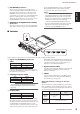
Part Names and Functions
MY16-ES64 Owner’s Manual
5
C
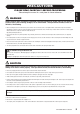
[HA REMOTE] Connector
This is a D-sub 9-pin connector that enables remote
control of a Yamaha AD8HR or AD824 AD converter via
EtherSound. In most situations, you will connect to the
[REMOTE] connector of the host device using a serial
cross cable. If you use a host device, such as Yamaha digital
mixer LS9, which is capable of remotely controlling
directly via a slot connection, you do not need to connect
this [HA REMOTE] connector to the host device.
D
[NEXT MY16-EX IN][NEXT MY16-EXOUT]
Connectors
These RJ-45 connectors can be connected via an Ethernet
cable (CAT5e or higher category) to the [MASTER SIDE
IN] or [MASTER SIDE OUT] connector of the Yamaha
MY16-EX I/O expansion card for transmission and
reception of the audio and word clock signals.
NOTE:
• Use an STP (Shielded Twisted Pair) cable to prevent
electromagnetic interference. Using a UTP (Unshielded
Twisted Pair) cable may cause noise or cut off sound.
Also, be sure to attach the ferrite core included with the
MY16-EX to a location close to the cable plug
connected to the [NEXT MY16-EX OUT] connector.
• Do not use cables that feature protective boots for their
plugs as they could come in contact with the cable
connected to the [HA REMOTE] connector.
■
Switches
Set these switches as appropriate for your situation and for the device in which the card is installed.
A
Signals via [HA REMOTE] Connector
(SW1)
Typically set this switch to the [422] position. When you
connect the [HA REMOTE] connector to a computer, set
this switch to the [232] position.
B
Sampling Frequency (SW2)
NOTE:
This card supports only Double Speed mode when
running at 88.2/96kHz. (Double Channel mode is not
supported.)
C
Card ID (SW3)
Typically set this switch to the [Emu.] position. If you set
this switch to the [Emu.] position and switch
2
(SW2) to
the [48K] position, the host device will recognize the card
as a Yamaha MY16-AT digital I/O card. If you set this
switch to the [Emu.] position and switch
2
(SW2) to the
[96K] position, the host device will recognize the card as a
Yamaha MY8-AE96 digital I/O card. If you install the card
in a host device whose firmware supports the MY16-ES64,
setting this switch to the [Nat.] position enables you to
make best use of the MY16-ES64 function.
D
Operation Mode (SW4)
Typically set this switch to the [OnChip] position. You will
set this switch to the [BOOT] position to update the
firmware in the future.
E
SW201
Leave this switch permanently set to the [OFF] position
during use. Please do not change this setting. Otherwise
the card will not operate properly.
Word Clock Master Settings on the host
devices
The word clock master settings will differ as per the following
chart, depending on whether the MY16-ES64 card(s) (that are
not a primary master) have been installed in the same device as
the primary master MY16-ES64 card.
* SLOT:
Indicates the slot in which the MY16-ES64 is installed.
SW3
SW1
SW4
232 422
Emu.SW248K
96K
OnChip
BOOT
Nat.
1234
5
SW201
OFF
Mode Position
RS-232C 232
RS-422 422
Mode Position
44.1/48 kHz 48K
88.2/96 kHz 96K
Mode Position
Emulation Emu.
Native Nat.
Primary Master
Other than Primary
Master
If installed in
different
devices
Select other than
“SLOT”
Select “SLOT”
If installed in
the same
device
Select other than “SLOT”