DIGITAL MIXING ENGINE Owner’s Manual EN
Explanation of Graphical Symbols CAUTION RISK OF ELECTRIC SHOCK DO NOT OPEN CAUTION: TO REDUCE THE RISK OF ELECTRIC SHOCK, DO NOT REMOVE COVER (OR BACK). NO USER-SERVICEABLE PARTS INSIDE. REFER SERVICING TO QUALIFIED SERVICE PERSONNEL. The lightning flash with arrowhead symbol within an equilateral triangle is intended to alert the user to the presence of uninsulated “dangerous voltage” within the product’s enclosure that may be of sufficient magnitude to constitute a risk of electric shock to persons.
FCC INFORMATION (U.S.A.) 1. IMPORTANT NOTICE: DO NOT MODIFY THIS UNIT! This product, when installed as indicated in the instructions contained in this manual, meets FCC requirements. Modifications not expressly approved by Yamaha may void your authority, granted by the FCC, to use the product. 2. IMPORTANT: When connecting this product to accessories and/ or another product use only high quality shielded cables. Cable/s supplied with this product MUST be used. Follow all installation instructions.
PRECAUTIONS PLEASE READ CAREFULLY BEFORE PROCEEDING * Please keep this manual in a safe place for future reference. WARNING Always follow the basic precautions listed below to avoid the possibility of serious injury or even death from electrical shock, short-circuiting, damages, fire or other hazards. These precautions include, but are not limited to, the following: Power supply/Power cord Water warning • Only use the voltage specified as correct for the device.
Maintenance Backup battery • Remove the power plug from the AC outlet when cleaning the device. Handling caution • Do not insert your fingers or hand in any gaps or openings on the device (vents, ports, etc.). • Avoid inserting or dropping foreign objects (paper, plastic, metal, etc.) into any gaps or openings on the device (vents, ports, etc.) If this happens, turn off the power immediately and unplug the power cord from the AC outlet.
Foreword Foreword Thank you for choosing a Yamaha DME64N/24N Digital Mixing Engine. Using the supplied DME Designer software, the DME64N and DME24N can be easily configured to handle a wide range of audio processing applications – institutional audio installations, sub-mixing, speaker system control, matrix and routing, multi-effect processing, and much more.
Contents Foreword 8 Accessories (Please make sure the following items are included in the package.). . . . . . . . . . . 8 Options . . . . . . . . . . . . . . . . . . . . . . . . . . . . . . . . . . 8 About the Product Names . . . . . . . . . . . . . . . . . . 8 About the Firmware Version. . . . . . . . . . . . . . . . . 8 Preparation. . . . . . . . . . . . . . . . . . . . . . . . . . . . . . . 8 Connecting the AC power cord . . . . . . . . . . . . . . . . . . . . . .8 Turning the power on and off . . . .
Accessories (Please make sure the following items are included in the package.) Foreword Thank you for choosing a Yamaha DME64N/24N Digital Mixing Engine. In order to take full advantage of the features and performance provided by the DME64N/24N, we urge you to read this owner’s manual thoroughly before connecting or using the unit. Keep this manual in a safe place for future reference. Foreword Accessories (Please make sure the following items are included in the package.
Differences between DME64N/24N Introduction to the DME64N/24N Differences between DME64N/24N The DME64N has four I/O card slots, while the DME24N has one I/O card slot and eight channels of builtin analog audio I/O. A single I/O card can handle up to 16 channels of audio I/O, so the DME64N can handle a maximum of 64 audio I/O channels. The DME24N can handle up to 24 audio I/O channels. The DME64N has approximately double the DSP processing power of the DME24N.
Glossary for the DME64N/24N Scene A combination of all configuration and preset parameters is called a “scene.” Scenes can be recalled from an ICP1, GPI device, other external controllers, DME64N/DME24N, or computer. Up to 999 scenes can be stored for each device group. Scene structure Scene Preset Parameter Configuration Matrix Mixer Scene 1 Ex.
Signal Types Signal Types DME64N/24N audio system signals can be broadly categorized as follows. 1 Audio The DME64N/24N will be required to send and receive audio signals to and from other DME series units as well as other audio equipment. Audio signal transmission and reception will occur primarily via the [INPUT] and [OUTPUT] connectors on the DME24N. 2 Control signals within a device group Introduction to the DME64N/24N Device group control signals control all DME series devices in the group.
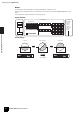
System Examples System Examples Large systems using CobraNet Space A Space B Computer ICP1 DME24N 1 Network Switch EXT. CLOCK NETWORK 96kHz MID 88.2kHz MASTER 48kHz 2 3 4 2 3 4 5 6 7 8 5 6 7 8 Analog Out Analog In PEAK IN SIGNAL 1 44.1kHz PEAK SCENE NUMBER OUT SIGNAL MY16-CII Network Switch DME24N 1 EXT. CLOCK NETWORK 96kHz MID 88.2kHz MASTER 48kHz 2 3 4 2 3 4 5 6 7 8 5 6 7 8 PEAK 1 Analog Out Analog In IN SIGNAL 44.
About DME Designer About DME Designer DME64N/DME24N Owner’s Manual Introduction to the DME64N/24N DME Designer software enables you to integrate, configure, and control the DME series system from a connected computer. You can build the DME series audio system using graphic blocks in DME Designer that are displayed on the computer monitor. The DME series settings, configuration, and parameter data are transferred from the computer to the DME series unit via the USB or Ethernet connection.
Front Panel The Controls and Connectors Front Panel DME64N The Controls and Connectors SCENE HOME UTILITY LEVEL MUTE CANCEL ENTER SCENE HOME UTILITY LEVEL MUTE CANCEL ENTER DME24N [USB] Connector A computer can be connected here when it is necessary to program or control the device. When a USB connection is to be used, the USB-MIDI driver must be installed on the computer. Refer to the DME Designer Installation Guide for installation instructions. [EXT.
Front Panel [MIDI] Indicator Lights while data communication is occurring via the [MIDI] connector. Received data causes the indicator to light green, while transmitted data causes the indicator to light orange. The indicator will light green when reception and transmission occur simultaneously. If a problem occurs the indicator will light red. [MUTE] Button Calls the mute display (page 39). The indicator will light orange when mute is on.
Rear Panel Rear Panel DME64N DME24N The Controls and Connectors [AC IN] Connector This is the device’s three-pronged AC power connector. Connect to the AC mains using the supplied AC power cord. See “Setup” on page 18 for details. NOTE Use the supplied AC cord clamp to prevent accidental disconnection of the AC power. CAUTION Even when the power switch is turned off, electricity is still flowing to the product all the minimum level.
Rear Panel [NETWORK] Connector This is a 100Base-TX/10Base-T Ethernet connector for connection to a computer or other DME series units. Normally this connector will be connected to a network switch via an Ethernet cable. When two DME64N/24N units are to be directly connected a “cross” cable should be used. See “Ethernet Connection ([NETWORK] Connector)” on page 23 for connection details. NOTE Use a STP (Shielded Twisted Pair) cable for this connection to prevent electromagnetic interference.
Setup Procedure Setup Setup Procedure Follow the steps outlined below to prepare the DME64N/24N for operation. 1. Install any required I/O cards. Refer to “I/O Card Installation” on page 20 for details. 2. Connect the AC power cord. CAUTION Be sure to turn all devices OFF before connecting AC mains power. Attach the cable clamp to prevent accidental disconnection. Attaching the cable clamp. Setup Be sure to properly ground the device to prevent possible electrical shock.
Setup Procedure 4. Connect devices. • Network connection Ethernet connection (page 23) USB connection (page 22) • Analog connection (page 26) • External device connection Remote connection (page 28) MIDI connection(page 30) CASCADE connection(page 31) WORD CLOCK connection(page 32) GPI connection (page 33) 5. Turn power to the computer, DME64N/24N, and related devices on. Press the DME64N/24N [POWER] switch to turn it on.
I/O Card Installation I/O Card Installation The DME64N has four I/O card slots, and the DME24N has one I/O card slot. The number of audio input channels available on the DME64N/24N can be increased by plugging the appropriate Mini-YGDAI I/O card(s) into the available card slot(s). Compatible I/O Cards For the latest information on what cards can be used with the DME64N/24N, visit the Yamaha Pro Audio website at: http://www.yamahaproaudio.
I/O Card Installation I/O Card Installation Procedure 1. Make sure that the DME64N/24N power is OFF. If the power is on, turn it off. 2. Loosen the two card slot screws and remove the slot cover, as shown in the diagram. NOTE 3. Setup The slot cover and screws will need to be re-attached if the I/O card is later removed from the slot, so keep them in a safe place. Slide the I/O card into the slots in the guide rails, as shown in the diagram, and push the card into the slot.
USB Connection Connecting to a Computer USB Connection NOTE • Refer to the “DME Setup Manual” (PDF file) for details on installing USB-MIDI Driver and DME Designer. • Make sure that the USB-MIDI Driver’s THRU setting is “OFF.” USB connections can be used in the following two ways: (1) Control the DME64N/24N from DME Designer. (2) Connect to any individual DME64N/24N and control that DME64N/24N unit by transmitting MIDI commands from a MIDI sequencer or similar software.
Ethernet Connection ([NETWORK] Connector) Ethernet Connection ([NETWORK] Connector) To control the DME64N/24N from the computer via Ethernet, use an Ethernet cable to connect the [NETWORK] connector on the rear panel of the DME64N/24N to the computer, then install DME-N Network Driver. NOTE • Refer to the “DME Setup Manual” (PDF file) for details on installing DME-N Network Driver. • Appropriate IP addresses must first be assigned to all devices connected to an Ethernet network.
Ethernet Connection ([NETWORK] Connector) Control from a computer in the same subnet group Device Group Group Master INPUT USB PEAK PEAK PEAK SIGNAL SIGNAL SIGNAL PEAK PEAK PEAK SIGNAL SIGNAL SIGNAL DIGITAL MIXING ENGINE SATELLITE INPUT DME Satellite (IP address: 192.168.0.7) Ethernet Cable Ethernet Cable Network Switch Ethernet Cable Computer (IP address: 192.168.0.
Ethernet Connection ([NETWORK] Connector) Connecting multiple device groups Device Group 1 Device Group 2 Group Master Group Master INPUT USB INPUT PEAK PEAK PEAK SIGNAL SIGNAL SIGNAL DIGITAL MIXING ENGINE SATELLITE USB PEAK PEAK PEAK SIGNAL SIGNAL SIGNAL PEAK PEAK PEAK PEAK PEAK PEAK SIGNAL SIGNAL SIGNAL SIGNAL SIGNAL SIGNAL INPUT DIGITAL MIXING ENGINE SATELLITE INPUT DME Satellite (IP address: 192.168.0.2) Ethernet Cable DME Satellite (IP address: 192.168.0.
Analog Audio Connection ([IN] and [OUT] Connectors) Audio I/O Connection Analog Audio Connection ([IN] and [OUT] Connectors) (DME24N only) The DME24N includes [IN] and [OUT] connectors for 8 channels of analog audio input and output. Wire the supplied Euroblock plugs as shown below. Head amplifier gain and phantom power settings can be made via the Utility display HA page described on page 52 of this manual, or via the DME Designer application.
I/O Slots 3. Securely tighten terminal screws. Pull the cables (not too strongly) to confirm that they are securely connected. 4. Plug the Euroblock plug into the panel connector. I/O Slots Audio I/O Connection The DME64N has four I/O card slots, and the DME24N has one I/O card slot. The number of audio input channels available on the DME64N/24N can be increased by plugging the appropriate Mini-YGDAI I/O card(s) into the available card slot(s).
Remote Connection ([REMOTE] Connector) Connecting to an External Device Remote Connection ([REMOTE] Connector) The [REMOTE] connector of the DME64N/24N can be connected to remotely-controllable Yamaha AD8HR or AD824 head amplifiers (pre-amps), digital mixers, or RS-232C compatible controllers (such as those from AMX or Crestron). The [REMOTE] connector also transmits and receives MIDI messages.
Remote Connection ([REMOTE] Connector) Controlling a DME24N’s internal head amps from a digital mixer The internal head amp settings of a DME24N can be remotely controlled from a digital mixer such as the Yamaha PM5D or DM2000. Connect the digital mixer to the DME series’ [REMOTE] connector, and use an Ethernet cable to make connections between the [NETWORK] connectors of the DME series. From the digital mixer, DME series units can be controlled as an AD8HR.
Network Connection ([NETWORK] Connectors) Network Connection ([NETWORK] Connectors) You can connect a controller such as the AMX or Crestron to DME64N/24N via Ethernet, and remotely control multiple DME64N/24N units. For details about the settings, refer to the “Rmt Ctrl” in “Remote page” on page 48. • The port used for remote control is specified from DME Designer. For details on making this setting, refer to the “DME Designer Owner’s Manual.
Cascade Connection ([Cascade] Connectors) (DME64N only) Cascade Connection ([Cascade] Connectors) (DME64N only) The rear-panel [CASCADE] connector can be connected to the [CASCADE] connector on another DME64N/24N or other compatible device via a dedicated cascade cable for bidirectional transfer of control, audio, and word clock signals.
WORD CLOCK Connection ([WORD CLOCK] Connectors) WORD CLOCK Connection ([WORD CLOCK] Connectors) Word clock signals are transferred to and from external devices via the [WORD CLOCK IN] and [WORD CLOCK OUT] connectors. The [WORD CLOCK OUT] connector can be used to supply the DME64N/24N word clock to external equipment. Word clock is continuously output by the DME64N/24N during normal operation. The word clock signal from an external device can be received via the [WORD CLOCK IN] connector.
GPI Connection ([GPI] Connectors) GPI Connection ([GPI] Connectors) GPI (General Purpose Interface) device (GPI controller, etc.) can be connected to the rear-panel [GPI] connectors. Using GPI a variety of control signals can be transferred between the DME64N/24N and external controllers or other devices. The optional CP4SW, CP4SF, and CP1SF control panels are also connected via GPI.
Basic Operation Panel Operation and Displays Basic Operation By pressing the panel buttons it is possible to select the DME64N/24N Main display, Utility display, and Parameter Edit displays that allow individual settings to be edited and changed. refer to the pages listed below for more detailed information about each display. [HOME] button Main Display (page 35) The Main display can be directly recalled from any display other than the Main display by pressing the [HOME] button.
Main Display Main Display The Main display will appear in a few seconds after the power is turned on. The Main display shows information about the current scene. NOTE Nothing will appear on the display if no scene data is stored in the DME64N/24N scene memory (this is the case when the unit is initially shipped, for example). Up to 24 parameters can be accessed from the DME64N/24N or ICP1 control panel for each scene. Six parameters are shown on the Main display at a time.
Parameter Edit Displays Parameter Edit Displays Panel Lock The panel controls can be “locked” to prevent accidental mis-operation. To activate the panel lock function simultaneously press and hold the [HOME] and [ENTER] buttons for longer than 2 seconds. The panel lock icon will appear on the Main display when the panel is locked. Panel lock icon Panel Lock can be disengaged by pressing the [CANCEL] button for longer than 2 seconds.
Parameter Edit Displays Some Parameter Edit displays have just one numeric parameter, while other may have two or more. 2. Rotate the dial to edit the value as required. 3. Repeat step 1 to select the next value to be edited, use the dial to edit as required, and repeat until all values have been edited as required. 4. When all values have been edited, press the [ENTER] button. A confirmation window will appear: press [ENTER] one more time to confirm the edits and close the window.
Parameter Edit Displays List Parameters ON/OFF Parameters List parameters allow you to make one selection from a list of possibilities. Parameters that are either ON or OFF are edited via this type of display (e.g., Mute Parameter Edit display in “Mute Switching” on page 39). Rotate the dial to scroll up or down the list.
Parameter Edit Displays Mute Switching Turns the DME64N/24N output mute function ON or OFF. 1. Scene Recall This procedure recalls a new scene (refer to page 10). Press the [MUTE] button. NOTE The Mute Parameter Edit display will appear. The same procedure is used for scene recall from an ICP1 control panel. 1. Press the [SCENE] button. The Scene Recall display will appear. 2. Select Mute ON or OFF. The mute function is turned on or off as described in “ON/OFF Parameters” on page 38.
Parameter Edit Displays NOTE Scenes can also be changed from a computer or GPI/ MIDI controller connected to the device. The DME Designer application is used to make scene changes from a computer. If a GPI/MIDI controller is to be used for changes it must be initially set up for scene change control by using the DME Designer. Monitoring The monitor functions allow you to monitor the audio signal at the inputs or outputs of I/O slots, points between components, and other critical monitoring points.
Spectrum Display 3. Select the desired monitor point from the list. Spectrum Display The audio signal from the selected monitoring point will be output via the PHONES jack and the [MONITOR] indicator lights up. The monitor functions also provide spectrum analyzer type level display of the signal at the selected monitor point. NOTE NOTE Press the [CANCEL] button to move back to the previous edit display. Spectrum display is not available on the ICP1 control panel.
Level Meter Display Level Meter Display Individually displays the input/output level for each channel. NOTE Level display is not available on the ICP1 control panel. 1. Make sure that the Main display is showing. If the Main display is not showing, press the [CANCEL] to return. 2. Initializing the DME64N/ DME24N The DME64N/DME24N and ICP1 internal memories can be initialized as follows. Begin with the power turned off.
Utility Displays Utility Displays Most basic DME64N/24N functions can be accessed via the Utility Display. Items accessible via the Utility display Page Item Info Description Manual Page Current status and settings for the devices basic parameters. Label Page 45 Name display. Version The device’s current version number. Date Current status and setup for the internal calendar/clock. Battery Shows the status of the internal battery.
Utility Displays Page Item Displays info about an I/O card installed in a DME64N/24N I/O slot. Slot Card name Displays the name of the installed card. (no title) Resets the installed card. Format Reset Resets the GPI calibration. Max Sets the maximum calibration value. Min Sets the minimum calibration value. (no title) HA Current status and setup for head amplifier type. WCLK Current status and setup for the word clock used by the head amplifier(s).
Utility Displays Utility Display Operation The general procedure for operating the Utility displays is outlined below. 1. Press the [UTILITY] button for longer than 2 seconds from the Main display to go to the Utility display. 2. Press the [UTILITY] button as many times as necessary until the desired parameter page appears. Program Version This is the current firmware version number. Date Shows the currently set date and time. The internal clock and calendar can be set here.
Utility Displays Network Settings (Net) Page Shows the Ethernet network address and other parameters. NOTE If the IP address of the DME device is changed after the device has been synchronized with DME Designer, it will be necessary to re-transfer the configuration data by performing a “Full Resync” operation. Refer to the “Online” section in Chapter 2 of the DME Designer Owner’s Manual for details about the “Full Resync” operation. Master ID Displays and sets the device group master host address.
Utility Displays LCD Contrast The current LCD contrast setting. This parameter can be adjusted from 0% through 100%. Edit using the “Numeric Parameters” editing procedure described on page 36. LCD Backlight Specifies LCD backlight operation. Two settings are available: “ON,” and “OFF.” ON: The display is continuously lit. OFF: The display lights when a control is operated, and will go out 10 seconds after panel operation ceases. Pressing the [ENTER] button alternately selects “ON” and “OFF”.
Utility Displays Miscellaneous Setup (Misc) Page This page includes parameters not available in any other page. Event Scheduler Determines whether an event schedule setup in the DME Designer will be executed or not, and displays the current status. This parameter can be set to “ON” or “OFF.” ON: The event will be executed. OFF: The event schedule will not be executed. Edit using the “List Parameters” editing procedure described on page 38.
Utility Displays Ext HA Ctrl (External head amp control) Displays/sets the type of connection to be used for external head amp control. OFF: Select “OFF” when this function is not to be used. Remote (422): Allows remote head amp control. Always use this setting when a remote head amp unit (AD8HR, AD824) is connected. Also, don’t change the setting while a remote head amp is connected. Doing so can damage the unit. COM Displays/sets the type of connection to be used for DME communication Protocol.
Utility Displays Protocol (MIDI Protocol Setup) Displays/sets the protocol to be used for communication with devices connected via MIDI. The available settings are: MIDI, DAW(Type1), and DAW(Type2). MIDI: Use this setting when any MIDI device other than a general-purpose ProTools controller (HUI protocol) or general-purpose Logic or Cubase controller (Mackie control protocol) is to be connected. DAW (Type1): Use this setting when a generalpurpose ProTools controller (HUI protocol) is to be connected.
Utility Displays SLOT1~4 Shows the status of the word clock signal input via I/O cards installed in the I/O slots. GPI Setup (GPI) Page Input calibration parameters for the [GPI] connector. The Status Icons A word clock signal is present, and this signal can be selected as the DME64N/24N word clock. NOTE This page will not appear on the ICP1 display. No word clock signal (cannot be selected as the master clock). A word clock signal is present, but is not in sync with the master word clock.
Utility Displays Head Amplifier Setup (HA) Page Provides access to the head amplifier settings. Refer to “REMOTE Connection” on page 28 for head amplifier control signal connection. NOTE This page will not appear on the ICP1 display. NOTE Some scenes include head amplifier settings. In such cases, the HA page settings will be saved along with the scene when it is stored.
Utility Displays NOTE The gain of the DME24N internal head amplifiers can be adjusted from +10 dB to –60 dB in 1-dB increments. The internal circuitry switches at about the –45-dB point, and the signal is automatically muted at that point to prevent noise. The AD8HR gain can be adjusted from +10 dB to –62 dB in 1-dB steps, and the AD824 gain can be adjusted from +10 dB to –62 dB in 6-dB steps.
Utility Displays NOTE Make sure that the Mixer I/O setting is the same for all cascaded DME64N/24N units. Check Page Even in an environment with no computer, you can check the connections without using DME Designer by directly connecting the DME64N/24N input/output. The meter does not operate during a connection check. MODE: OFF Makes connections in the configuration used in the current scene. This is set to OFF when the unit is started.
Options References Options The ICP1, CP4SW, CP1SF, and CP4SF controllers are available as options for remote external control of the DME series. The ICP1 connects via Ethernet, while the CP4SW, CP1SF, and CP4SF connect via the GPI interface. For more information on installing your Control Panel and connecting it to a DME series unit, refer to the owner’s manual that came with the Control Panel. For more information on settings, refer to the DME Designer Owner’s Manual.
Error Messages Error Messages Message Meaning Action Error messages References Cannot Select No selectable items are available in the scene or monitoring point list display. Make the appropriate settings via the DME Designer application. Component Corrupt Update Firmware! The component data is corrupt or can’t be found. Restart after updating the component using DME Designer. If the error indicators are still indicating the error, execute the “Delete All Data” initialization.
Error Messages Meaning Action CAS. In Sync Err The DME64N/24N clock is not in sync with the clock signal being received at the [CASCADE IN] connector. Make sure that the DME64N/24N and the card or external source supplying the word clock are set to use the same word clock. CAS. Out Sync Err The DME64N/24N clock is not in sync with the clock signal being received at the [CASCADE OUT] connector.
Error Messages Message Meaning Action Scene Recalling Do not turn off Scene recall in progress. Do NOT turn power off while the unit displays this message. — Scene Storing Do not turn off Scene store in progress. Do NOT turn power off while the unit displays this message. — Searching for Master DME Unit... Currently searching for the master DME unit. — Searching for Slave DME Unit... Currently searching for the slave DME unit.
Troubleshooting The power won’t turn on, and the panel indicators and LCD won’t light. • Is the power cable properly connected? • Is the POWER switch turned on? • If neither of the above is the problem, contact your Yamaha service center or representative. Cannot exchange data between the DME64N/24N and the DME Designer.
Specifications Specifications Specifications and descriptions in this owner’s manual are for information purposes only. Yamaha Corp. reserves the right to change or modify products or specifications at any time without prior notice. Since specifications, equipment or options may not be the same in every locale, please check with your Yamaha dealer. Sampling Frequency Internal 44.1kHz, 48kHz, 88.2kHz, 96kHz External Normal Rate: 39.69 – 50.88kHz Double Rate: 79.39 – 101.76kHz DME64N: 0.
Input/Output Characteristics Input/Output Characteristics Gain CH INPUT -60dB 1–8 +10dB Actual Load Impedance 3kΩ Input Level Connector Max. before clip For Use With Nominal Nominal 50 – 600Ω Mics & 600Ω Lines -60dBu (0.775mV) +10dBu (2.451V) Input CH INPUT 1–8 DME24N ANALOG INPUT CHARACTERISTICS Terminals Gain Error @1kHz -40dBu (7.75mV) +30dBu (24.511V) Internal OSC Input CH INPUT 1–8 DME64N ANALOG OUTPUT CHARACTERISTICS PHONES 15Ω For Use With Nominal 8Ω 40Ω Output Level Max.
Control I/O Control I/O Terminals REMOTE Format Connector - RS232C - RS422 D-SUB Connector 9-pin (Male) Baud Rate = 38,400 bps Data = 8bit Stop bit = 1bit PARITY = NON MIDI IN/OUT/THRU - DIN Connector 5P WORDCLOCK IN/OUT TTL/75Ω BNC Connector Ethernet Ethernet - RJ-45 USB USB 0 – 3.3V USB Type B (Female) GPI IN 0 – 5V Euroblock Connector OUT TTL +V 5V DME64N: 16-GPI inputs and 16-GPI outputs DME24N: 8-GPI inputs and 8-GPI outputs Outputs: Imax/pin = 16mA Outputs: VH = 2.
Connector Pin Assign Connector Pin Assign [CASCADE IN/OUT] Connectors (DME64N only) CASCADE IN Pin No. Signal CASCADE OUT Pin No. Signal Pin No. Signal Pin No.
Connector Pin Assign [NETWORK] Connector (100Base-TX Ethernet, RJ-45) Pin Connection 1 TxD+ 2 TxD– 3 RxD+ 4 Unused 5 Unused 6 RxD– 7 Unused 8 Unused Straight/Cross Cable Wiring Details Straight Cables Pins Pins 1 —— 1 1 —— 3 2 —— 2 2 —— 6 3 —— 3 3 —— 1 4 —— 4 4 —— 4 5 —— 5 5 —— 5 6 —— 6 6 —— 2 7 —— 7 7 —— 7 8 —— 8 8 —— 8 References 64 Cross Cables DME64N/DME24N Owner’s Manual
Dimensions Dimensions Unit: mm 12.5 53.5 278 388 411.5 394 405 11 DME64N 423 145 17.5 96 132 18.5 4-M3 90 30 300 90 480 12.5 References 53.5 278 388 411.
MIDI Data Format MIDI Data Format 1. DME64N/24N MIDI Functions 1.1 Scene Change Scene recall occurs according to the “MIDI Program Change Table” assignments when appropriate MIDI Bank Select MSB/LSB and Program Change messages are received by the DME64N/24N. Corresponding MIDI Bank Select MSB/LSB and Program Change messages are also transmitted by the DME64N/24N when a scene recall operation is carried out via the panel controls, as specified by the “MIDI Program Change Table” assignments.
MIDI Data Format 3. MIDI Setup Specifies basic MIDI operation. 3.1 Host Select Selects the input/output port to be used for MIDI communication. 3.2 DAW Controller Specifies the DAW controller type when a DAW control surface is to be used to control the DME64N/24N. When Type 1/2 is selected, Host Select is automatically set to MIDI. 3.3 MIDI Tx Channel Specifies the MIDI transmit channel (1 ~ 16). 3.4 MIDI Rx Channel Specified the MIDI receive channel (1 ~ 16). 3.
MIDI Data Format 4.1 Program Change (Cnh) Receive When the “Program Change Rx Switch” is on, Program Change messages are received on the MIDI channel specified by the “MIDI Rx Channel” parameter. If the “Program Change Omni Switch” is also on, however, Program Change messages will be received on all MIDI channels regardless of the “MIDI Rx Channel” setting. When a Program Change message is received, the scene assigned to the received program number in the “MIDI Program Change table” is recalled.
MIDI Data Format Transmit When the “Parameter Change Tx Switch” is On, appropriate Parameter Change data will be transmitted when a parameter is edited via the panel controls, as specified by the “MIDI Parameter Change table” and “MIDI Tx Channel” settings. Refer to “Supplementary Information 1” for cases in which multiple messages are assigned to single parameter. Refer to “Supplemental Information 2” for information on setting Parameter Data values. Status ID No. DEVICE ID. GROUP ID. MODEL ID.
MIDI Implementation Chart YAMAHA [Digital Mixing Engine] Model DME64N/24N MIDI Implementation Chart MIDI Implementation Chart Function... Transmitted Recognized Basic Channel Default Changed 1 1 Mode Default Messages Altered × × ************** × × × × ************** × × Note Number : True voice - 16 16 1 1 Velocity Note ON Note OFF × × × × After Touch Key’s Ch’s × × × × × × Pitch Bend 0,32 1-31,33-95,102-119 O O Date :31-MAR-2004 Version : 1.
Glossary Glossary Explanations 100Base-TX A physical specification for a 100 Mbps Ethernet network connection using 2-conductor Category 5 UTP cable included in the IEEE 802.3u standard. Maximum data transfer distance is 100 meters. 10Base-T A physical specification for a 10 Mbps Ethernet network connection using 2-conductor Category 3 UTP cable included in the IEEE 802.3i standard. Maximum data transfer distance is 100 meters.
Glossary Terms RS-232C A serial communication protocol that allows data transfer over distances of up to 15 meters. RS232C interfaces usually employ 9-pin D-sub connectors. “RS” stands for “Recommended Standard,” and one of the standards developed by the EIA (Electronic Industry Alliance). RS-422 A balanced serial communication protocol that allows data transfer over distances of up to 1 kilometer. RS-422 offers higher data rates and greater reliability than the RS-232C protocol.
Index +48V ............................................................................ 53 [E] [] [] [F] Buttons ............................................... 15 100Base-TX (Glossary) ............................................... 71 10Base-T (Glossary) .................................................... 71 [96kHz] [88.2kHz] [48kHz] [44.1kHz] Indicator ............ 14 Display ......................................................................... 15 Display Setup (Disp) Page .......................
Int ................................................................................. 50 IP Adr. .......................................................................... 46 L L/R Select .................................................................... 41 Label ............................................................................ 45 LCD Backlight .............................................................. 47 LCD Contrast ...............................................................
T troubleshooting ............................................................ 59 U Unit No ......................................................................... 53 USB (Universal Serial Bus) (Glossary) ........................ 72 USB Connection .......................................................... 22 [USB] Connector .......................................................... 14 USB-MIDI Driver .......................................................... 22 User Defined button .......................
MEMO 76 DME64N/DME24N Owner’s Manual
MEMO DME64N/DME24N Owner’s Manual 77
MEMO 78 DME64N/DME24N Owner’s Manual
For details of products, please contact your nearest Yamaha representative or the authorized distributor listed below. Pour plus de détails sur les produits, veuillez-vous adresser à Yamaha ou au distributeur le plus proche de vous figurant dans la liste suivante. NORTH AMERICA CANADA Yamaha Canada Music Ltd. 135 Milner Avenue, Toronto, Ontario, M1S 3R1, Canada Tel: 416-298-1311 U.S.A. Yamaha Corporation of America 6600 Orangethorpe Avenue, Buena Park, CA 90620, U.S.A.
Yamaha Pro Audio global web site: http://www.yamahaproaudio.com/ Yamaha Manual Library http://www.yamaha.co.jp/manual/ C.S.G.