NUAGE MASTER CONTROL SURFACE Ncs500-CT Operation Manual Using this manual This operation manual supports keyword searching and linking as follows. Keyword searching Searching for keywords is performed using your pdf viewer’s search function. If you are viewing this manual using Adobe Reader, type the term you wish to find into the Find toolbar and then press your computer’s [Enter] key. Jumping between pages If using Adobe Reader, you can jump forwards and backwards to various pages in this manual.
Contents Introduction ..........................................................................................3 How to Read the Manual .................................................................................... 3 Description of the Device ....................................................................4 Top Panel ........................................................................................................... 4 Front Panel ...........................................................
Introduction Introduction How to Read the Manual Types and Contents • Screens This manual predominantly uses screenshots of Windows. However, Mac screenshots are used when instructions of the function apply only to the Mac. Also, this manual uses screenshots of Nuendo 6. If you are using another version of Nuendo, the actual screenshots might not be the same. For details, refer to the Nuendo manuals (PDF) opened from the “Help” menu. • Getting Started This is the manual included with the device.
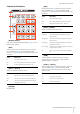
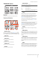
Description of the Device Description of the Device Top Panel DAW SELECT Section (page 24) TALKBACK MIC Section (page 25) MULTI FUNCTION DISPLAY Section (page 22) MONITOR SOURCE Section (page 6) CONTROL ROOM Section (page 5) AUTOMATION Section (page 22) CUES Section (page 8) USER ASSIGNABLE Section (page 21) TRANSPORT Section (page 10) COMMUNICATION Section (page 9) NUMERIC PAD Section (page 16) EDIT Section (page 11) GENERAL CONTROL Section (page 14) MODIFIER Section (page 15) JOG WHEEL Sectio
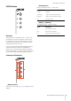
Description of the Device CONTROL ROOM Section [Display access] Calls up the “CONTROL ROOM Page” (page 38) in the [Multi function display]. When the CONTROL ROOM page is shown, you can toggle among the tabs of the CONTROL ROOM page. [DOWNMIX 1] – [DOWNMIX 4] Selects the Downmix presets. Lamp Description Lit Downmix preset has been selected. Dim Downmix preset has not been selected. [MONITOR A] – [MONITOR D] Selects the desired Monitor. Lamp Description Lit Monitor has been selected.
Description of the Device MONITOR SOURCE Section [REF] Sets the Control Room level to the Reference level. When this is on (lit), the level is reset to the Reference level. When you turn this is off (dim), the level is set back to the previous setting. The button goes dim when you change the level after turning this on. When you press [REF] while holding down the appropriate button(s) in the “MODIFIER Section” (page 15), the function changes as follows.
Description of the Device Controls and Functions [MIX] Switches to the “MIX” Control Room sources. However, when [PHONES] (page 5) in the CONTROL ROOM section is on, you can set the Phones source to “MIX” with this button. Lamp Description Lit The source is set to “MIX.” Dim One or more sources have been set to “MIX.” Off No sources have been set to “MIX” yet. [MIX 1] – [MIX 8] Selects the specific sources for “MIX.
Description of the Device CUES Section [SIG Indicators] Roughly indicates the CUE 1 – CUE 4 levels. Lamp Description Lit (red) Overload Lit (orange) -18 dB or more, but less than 0 dB Lit (green) -40 dB or more, but less than -18 dB Off Less than -40 dB [MUTE 1] – [MUTE 4] Turns Mute of CUE 1 – CUE 4 on and off. Lamp Description Lit Mute of CUE is turned on. Dim Mute of CUE is turned off. Off CUE has not been configured yet.
Description of the Device COMMUNICATION Section [C1]/[C2] Executes the assigned function. The button lights while held down. To assign the function, edit it from the “Communication Page” (page 45) in NUAGE MASTER Setup. Lamp Description Dim The function has been assigned. Off The function has not been assigned yet. [TALK BACK] Turns “Talkback” on (lit) and off. Each short press (of about 0.2 seconds) toggles this function on or off. Holding down the button keeps it in the “on” state until released.
Description of the Device TRANSPORT Section [SYNC ONLINE] Turns Synchronization on and off. Lamp Description Lit Synchronization is on. Dim Synchronization is off. Flash Synchronization is on; however, Nuendo has not yet received external time code or clock. [LEFT] Moves the Project Cursor to the Left Locator position. Overview This section is for operating the transport functions.
Description of the Device EDIT Section [ZAP] Recalls the memorized Project Window view, set by [MEM]. Pressing it again restores the view to the previous one. The button lights while being held down. Lamp Description Dim The memorized Project Window view can be recalled. Off The Project Window view has not been memorized to [MEM] yet. [] (fast rewind) Operates Fast Rewind. [] (fast forward) Operates Fast Forward. Overview This section contains Edit and Tools operations.
Description of the Device JOG WHEEL Section [CUT] Executes the Cut operation. The button lights while held down. Lamp Description Dim The Cut operation can be executed. Off No events have been selected yet. [COPY] Executes the Copy operation. The button lights while held down. Lamp Description Dim The Copy operation can be executed. Off No events have been selected yet. Overview [PASTE] Executes the Paste operation. The button lights while held down.
Description of the Device Controls and Functions [SELECT] Operates the Select function. The operation of the Select function differs depending on the selected Tools, Object Selection or Range Selection. To switch between Object Selection and Range Selection, use [OBJECT SELECT] (page 11) and [RANGE SELECT] (page 11) in the EDIT section, or do this within Nuendo, etc. When the Object Selection Tool is selected, you can select the event under the Project Cursor position in the selected channel.
Description of the Device GENERAL CONTROL Section [FADE IN] Operates the Fade In function. The following steps illustrate by example. 1. Select the desired event for applying Fade In. 2. Move the Project Cursor to the desired end, and press [FADE IN] to set it to that point. 3. Set the Fade In position by pressing [FADE IN]. In step 3 above, you can adjust the Fade In position more finely or to a different position by simultaneously holding down [FADE IN] and turning the [Jog wheel].
Description of the Device MODIFIER Section [UNDO] Executes Undo. The button lights while held down. To execute Redo, simultaneously hold down [SHIFT] (page 15) in the MODIFIER section and press [UNDO]. The button lights while held down. Overview Lamp Description Dim (green) Undo can be executed. Dim (orange) Redo can be executed (when [SHIFT] is pressed). Off Neither Undo nor Redo can be executed. This section contains the modifier buttons.
Description of the Device NUMERIC PAD Section Controls and Functions Overview [LOCATE] This section is for inputting various parameters by the [Input keys] — which include [0] – [9], [ENTER], [NEXT +], etc. The input parameter changes depending on the selected [Input keys] mode, all of which are listed below. The buttons used for selecting the respective modes are indicated in parentheses. Sets the [Input keys] mode to Locate.
Description of the Device Offset for addition/subtraction function Not applicable. Locate To Displays the Project Cursor position including the subtraction value. Locate To Inputs Project Cursor position. When the Subtraction function pop-up window is shown, the [Input keys] have the following functions. When the pop-up window for the Locate function is shown, the [Input keys] have the following functions. [Input keys] Function [0] – [9] For inputting numbers to the input position.
Description of the Device When the Addition function pop-up window is shown, the [Input keys] have the following functions. When the MARKER page is called up in the [Multi function display] [Input keys] Function [0] – [9] For inputting numbers to the input position. []/[] Moves the input digit right and left. [BACK SPACE] Deletes the number at the input position. [CLEAR] Deletes all input numbers. [SET] Selects the Set mode (the button lights).
Description of the Device Cycle Marker Jump Function In the Cycle Marker Jump function, you can set the Project Cursor to the Cycle Marker position by inputting the Marker ID of the Cycle Marker. When you press [CYCLE .] in the Marker mode, [CYCLE .] is lit, and the Cycle Marker Jump pop-up window is shown on the [Multi function display]. However, when the MARKER Page (page 42) in the TRANSPORT page is called up in the [Multi function display], the pop-up window is shown on the Label Pane area.
Description of the Device [DAW] Sets the [Input keys] mode to DAW. In the DAW mode, you can input values to parameters on the DAW software, using the [Input keys] instead of the numeric keys on the computer keyboard. In the DAW mode, the [Input keys] have the following functions. When you press any one of the buttons [0] – [9], []/[], [BACK SPACE], [CLEAR], [PREV -], [NEXT +], [CYCLE .], [ENTER] in the Wheel mode, the pop-up window for inputting the parameter is shown on the [Multi function display].
Description of the Device When the pop-up window is shown, the [Input keys] have the following functions. USER ASSIGNABLE Section [Input keys] Function [0] – [9] For inputting numbers to the input position. []/[] Moves the input digit to right and left. [BACK SPACE] Deletes the number at the input position. [CLEAR] Deletes all input numbers. [SET] Cancels the input then closes the pop-up window. [PREV -] Adds -1 to the input number. [NEXT +] Adds +1 to the input number.
Description of the Device AUTOMATION Section [TRIM] Turns Trim on (lit) and off (dim). MULTI FUNCTION DISPLAY Section Overview This section is for operating Automation. The function assignments of the buttons can be changed to other Automation functions as desired. For details on changing the function assignments, see “Automation window” (page 45) in NUAGE MASTER Setup. Controls and Functions Overview This section is for displaying and editing the section and channel parameters.
Description of the Device [Display access] at right side of the [Multi function display] The following chart indicates the relation between the “Label Pane” and the controllable parameters of the [Multi function knob]. Lit by touching knob Knob parameter value Functions on button A/B Knob Button A/B Depending on the page shown on the [Multi function display], the [Multi function knob] has the following functions. The [Multi function knobs] are touch-sensitive knobs for adjusting various parameters.
Description of the Device Controls and Functions DAW SELECT Section Overview [Multi function display] Displays pages for editing parameters in various sections, or pages for editing channel parameters. [Multi function knob] This section is for selecting the target DAW software for operation. This section allows you to select the particular DAW software when you have connected and configured multiple DAW software programs.
Description of the Device TALKBACK MIC Section Overview This is a section for the talkback microphone. Controls and Functions [TALKBACK microphone] Microphone for Talkback operation. The audio signal input to the [TALKBACK microphone] is output from the [TALKBACK OUT +4dBu] jack (page 27) on the rear panel.
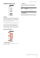
Description of the Device Front Panel [PHONES A/B] For connection to headphones. Audio input via [TO PHONES L/R] (page 27) on the rear panel is output here. [LEVEL] Adjusts the output signal level of [PHONES A/B].
Description of the Device Rear Panel [AC IN] For connection to the power cable. [RS-232C] For connection to an RS-232C cable. Connect this port to the RS-232C port on the KVM switch. When you switch between multiple DAW applications using the DAW SELECT section with KVM switches connected and the data to be sent to them configured in NUAGE Workgroup Manager, the display content, active keyboard, and active mouse will also change accordingly.
Description of the Software Programs Description of the Software Programs Pages Shown on the Multi Function Display To select the pages, press [Display access] in each section, or press the buttons at the right side of the MULTI FUNCTION DISPLAY section (page 22), or touch the tabs or buttons at the top of the pages. Each page has the following four areas.
Description of the Software Programs To input parameter values (which allow number input) in the page, use the Parameter mode in the NUMERIC PAD section (page 16). To do this: 1. Press [PARAM] (page 19) in the NUMERIC PAD section to select the Parameter mode. 2. Touch the parameter (which allows number input) shown on the [Multi function display] to select it. 3. Input the number with the [Input keys] (page 21) in the NUMERIC PAD section.
Description of the Software Programs • [VOLUME] (JOG WHEEL section) • [CYCLE] (TRANSPORT section) To scroll through the view of the Main area, touch “ on the Tool area. ”/“ ” • [] (record) (TRANSPORT section) • [TALK BACK] (COMMUNICATION section) When you set this to off, lighting of the buttons while they are held is disabled. SPL dB Sets “SPL dB.” By adjusting the value using the [Multi function knob] and then pressing [Multi function button A] (SET), you can set the value.
Description of the Software Programs When you touch the upper left of a folder track icon, the window changes to show the contents of the folder track. Controls and Functions Track Select View This view is for selecting tracks. Tracks For selecting the tracks. You can select multiple tracks by simply dragging across the tracks. In the first column, the selected folder track and a “Return” control is shown. Touching “Return” changes back to the previously selected window.
Description of the Software Programs Solo View Track This view is for operating Solo or Listen for the tracks. Turns Record Enable on (lit) and off. You can turn Record Enable on/off for multiple tracks by simply dragging across the tracks. When you touch “Track” while holding down the appropriate button(s) in the “MODIFIER Section” (page 15), the function changes as follows. Modifier button Function [ALT] Turns Record Enable on for only the last channel touched.
Description of the Software Programs When you touch “Channel information,” the channel selection window is shown. By touching “Nuendo” in the Tool area, you can open the channels configuration window on the screen. However, in the PLUG-IN page, the plug-in effect window is opened. Touch again to close. Controls and Functions MAIN Page This page is for operating Routing, Phase, Low Cut, etc. for the selected channel. To scroll through the window, touch “ ” or “ .
Description of the Software Programs S or L Turns Solo or Listen on (lit) and off. Level Meter Displays the channel level. Mon Turns Monitor on (lit) and off. Rec Dynamics Graph Displays the parameters as a graph. BYP Turns Bypass on (lit) and off. Preset Opens the preset selection window. Level Meter Turns Record Enable on (lit) and off. Displays the channel level. EQ Page SENDS Page This page is for operating EQ for the selected channel.
Description of the Software Programs CUES Page When Mix Convert is selected This page is for controlling the Cues of the selected channel. When a Stereo channel is selected Cue Send Level [PARAM] Adjusts the Cue send level. Cue Send Pan [PARAM] Adjusts the Cue send pan. On/Off Turns Cue on (lit) and off. PRE Turns Pre Fader on (lit) and off. BYP Turns Bypass on (lit) and off. PAN Page This page is for controlling Pan for the selected channel.
Description of the Software Programs INSERT Page 1. Touch the desired parameter in the Main area to select it. This page is for controlling Inserts for the selected channel. The parameter is temporarily assigned to an “empty” [Multi function knob] (one which does not yet have a locked parameter). NOTE If a parameter has already been locked, press the corresponding [Multi function button B] to unlock it. 2. Press [Multi function button B] of the desired [Multi function knob] to lock the parameter.
Description of the Software Programs AUTOMATION Page R Turns on Read Automation for all tracks. R Turns off Read Automation for all tracks. W Turns on Write Automation for all tracks. W Turns off Write Automation for all tracks. Overview This page is for controlling the Automation features. The functions of this page are the same as in the Nuendo Automation Panel. To open this page, press the AUTOMATION [Display access] button (page 22).
Description of the Software Programs USER ASSIGNABLE Page CONTROL ROOM Page Overview Overview This page is used to execute assigned functions. To open this page, press the USER ASSIGNABLE [Display access] button (page 21). To assign the function, configure it in “NUAGE MASTER Setup” (page 44). This page is for operating the Control Room functions. To open this page, press the CONTROL ROOM [Display access] button (page 5).
Description of the Software Programs SPEAKER CONTROL Page LE Turns Listen on (lit) and off. LE Level This page is for operating the Speaker Controls in Control Room. [PARAM] Adjusts Listen level. On/Off Turns the channel on (lit) and off. Level Meter Displays the channel level. Level Indicator [PARAM] Displays the channel level. Reference Level When turned on (lit), this resets the Control Room level to the Reference level. When this is off (dim), the previous level setting is restored.
Description of the Software Programs CUES Page MONITOR SOURCE Page Overview Overview This page is for operating Cue functions in the Control Room. To open this page, press the CUES [Display access] button (page 8). This page is for operating Monitor Source in the Control Room. To open this page, press the MONITOR SOURCE [Display access] button (page 7). Controls and Functions Controls and Functions EXT External Input Source Sets the source to “EXT.” Selects the source of the external inputs.
Description of the Software Programs COMMUNICATION Page TRANSPORT Page Overview Overview This page is for operating the communication functions in the Control Room. To open this page, press the COMMUNICATION [Display access] button (page 9). This page is for operating the Transport functions. To open this page, press the TRANSPORT [Display access] button (page 10). By touching “Nuendo” in the Tool area, you can open “NUAGE MASTER Setup” window (page 44) on the Nuendo screen. Touch again to close.
Description of the Software Programs TEMPO Function Selects the Tempo mode. Operates the Marker functions from the Marker window. SYNC / Turns Synchronization on (lit) and off. Time Display [PARAM] Sets the Project Cursor position. Scrolls through the Main area view. OVER VIEW Page This page is for operating the Overview functions. Transport Operates the basic Transport functions. MARKER Page This page is for operating the Marker Track functions. Overview Displays the overview of the project.
Description of the Software Programs EDIT Page Overview This page is used to execute assigned functions. To open this page, press the EDIT [Display access] button (page 11). To assign the function, configure it from “EDIT window” (page 44) in “NUAGE MASTER Setup.” To select the desired bank, touch “BANK 1” – “BANK 4” in the Title area, or press the EDIT [Display access] button. Each bank has twenty-four buttons, for a total of ninetysix.
Description of the Software Programs NUAGE MASTER Setup Controls and Functions User Assignable Settings Overview This software is for configuring the general settings of Nuage Master from Nuendo. You can configure settings such as the user assignable buttons on the device or “USER ASSIGNABLE page” (page 38). To open this window, click the Nuendo menu “Devices” “NUAGE MASTER Setup.” NUAGE MASTER Setup has the following windows. Assigns functions to the buttons.
Description of the Software Programs Edit Settings Assigns functions to the buttons. Click “Command” to select the command. When you check the “Repeat” box for the function, the corresponding function will operate continuously by holding down the button. You can input the desired function name to “Title.” Automation Window Communication Window Overview This window is for configuring the function of the buttons in the “COMMUNICATION section” (page 9) or “COMMUNICATION page” (page 41).
Description of the Software Programs NUAGE Workgroup Manager Overview NUAGE Workgroup Manager is an application that allows control over devices and DAW software programs as a Workgroup on a NUAGE system. For details on NUAGE Workgroup Manager, refer to the NUAGE Workgroup Manager manual (PDF). NOTE To open the NUAGE Workgroup Manager manual, double-click the NUAGE Workgroup Manager icon on the task tray (Windows) or menu bar (Mac) for opening the window, then click the “Manual” icon.
Troubleshooting (in operation) Troubleshooting (in operation) Appendix Contents of the Getting Started Manual A connection cannot be established with Pro Tools. • Ensure that the steps described in “Settings for Pro Tools” (page 48) have been completed. • If using a wireless LAN adaptor, try turning it off. PRECAUTIONS NOTICE Information Introduction A Message from the Development Team Included Accessories Values cannot be entered by touching parameters shown on the [Multi function display].
Appendix Pro Tools Control Setting Pro Tools MIDI Controllers 1. Start up Pro Tools. Introduction In addition to Nuendo and Cubase, Nuage Fader and Nuage Master devices can also be used to control Pro Tools (Mac only; basic functions only). NOTE • When working with Pro Tools, up to two Nuage Faders together with an optional Nuage Master can be connected. 2. Choose “Setup” “Peripherals” to open the “Peripherals” dialog. 3. Click the “MIDI Controllers” tab. 4.
Appendix Button Functions TRANSPORT Section [Display access] This button is used to open and close the Transport window. Its indicator lights up while the Transport window is open. [PRE ROLL] This button is used to turn on and off pre-roll. [POST ROLL] This button is used to turn on and off post-roll. [PUNCH IN] This button is used to turn quick punch on and off (same as the Quick Punch command in the Options menu). Its indicator lights up when quick punch is on. [PUNCH OUT] Same as above.
Appendix EDIT Section [Jog wheel] [Display access] This button is used to switch between the Edit and Mix windows. It is lit when the Edit window is active and is dim when the Mix window is active. [SNAP] Not applicable. [AUTO SCROLL] GENERAL CONTROL Section []/[]/[]/[] (up/left/down/right) These buttons can be used to scroll the Mix and Edit windows, navigate the Edit window, zoom waveforms, and to make fine adjustments to the selected region.
Appendix NUMERIC PAD Section [LOCATE] Not applicable. MULTI FUNCTION DISPLAY Section [Multi function display] [MARKER] [SETUP] [PARAM] [TRACK LIST] [DAW] [CHANNEL] [WHEEL] [PLUG-IN] [0] – [9] These buttons correspond to keys [0] to [9] found on Mac keyboards. [CLEAR] This button corresponds to the [Clear] key found on Mac keyboards. [CYCLE .] This button corresponds to the [.] key found on Mac keyboards. [PREV -] This button corresponds to the [-] key found on Mac keyboards.
Yamaha Pro Audio Global Web Site http://www.yamahaproaudio.com/ Yamaha Manual Library http://www.yamaha.co.jp/manual/ C.S.G.