
User Manual


15
P2500S
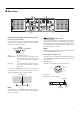
1/8 power is typical of program material with occasional clipping. Refer to these figures for most applications.
1/3 power represents program material with extremely heavy clipping.
Test signal: Pink Noise, bandwidth limited from 22Hz to 22kHz
1W = 0.860kcal/h, 1BTU = 0.252kcal
Note that Line Voltage [V] x Line Current [A] = [VA], not equals to [W].
Inrush current
P7000S, P5000S: 11A (100V), 13A (120V), 25A (240V)
P3500S: 142A (100V), 170A (120V), 66A (240V)
P2500S: 103A (100V), 150A (120V), 68A (240V)
Troubleshooting
The following table lists the main causes of abnormal operation and the corrective measures required, as well as the protective circuit opera-
tion in each case.
P3500S, P2500S
P7000S, P5000S
Line Current (A) Power (W) Thermal Dissipation
100/120V 230/240V In Out Dissipated Btu/h kcal/h
standby 0.080.04505174
idle 1.0 0.5 25 0 25 85 22
1/8 power
8Ω/ch 2.4 1.3 174 69 105 358 90
4Ω/ch 3.6 2.0 271 98 173 592 149
1/3 power
8Ω/ch 5.6 3.1 421 183 238 811 204
4Ω/ch 8.8 4.8 657 260 397 1350 341
Indicator(s)Possible Cause Remedy Protection Circuit
CLIP indicator lights.
There is a short at a s peaker
terminal, amplifier terminal, or
wire.
Locate and correct the cause of
the short.
The PC limiter circuit operates
to protect t
he pow
er
transistors.
The amplifier load is excessive.
Use a speaker system with an
impedance of at least 4 Ω
(STEREO/PARALLEL mode) or
8 Ω (BRIDGE mode).
TEMP indicator lights.
The heat sink temperature has
exceeded 85°C (185°F).
Check the ventilation slots, and
provide better airflow around
the amplifier.
The TEMP indicator lights up
to indicate temperature
war
ning.
PR
OTECTION indicator lights.
The heat sink temperature has
exceeded 95°C (203°F).
Check the amplifier ventilation
conditions and take appropriate
measures to improve the
airflow around the amplifier.
The thermal protection circuit
operates to protect the power
transistors.
Indicator(s)Possible Cause Remedy Protection Circuit
PROTECTION indicator lights.
A DC voltage of ±2 V or greater
was generated in the power
ampl
ifier’s ou
tput circuit.
Consult your dealer or the
nearest Yamaha service center.
The relay operates to protect
the speaker system.
Indicator(s)Possible Cause Remedy Protection Circuit
Power has been shut down. (All indicators
are off.)
A DC voltage of ± 2 V or
greater was generated in the
power amplifier’s output circuit.
Consult your dealer or the
nearest Yamaha service center.
The p
rotection circuitry shut off
the power to protect the
speaker system.