リファレンスマニュアル JA
目 次 はじめに .................................................................3 マニュアル構成 ............................................................... 3 時計の設定 (「5.Utility」→「Clock」)......................................15 対応アンプ ....................................................................... 3 GPI IN のキャリブレーション (「5.Utility」→「GPI Calibration」) ...................16 セットアップ ................................................................... 3 ネットワークの設定 (「6.Network Setup」)........16 用語.................
はじめに マニュアル構成 本書ではアンプコントロールデバイス ACD1の本体操作や仕様を中心に説明しています。ACD1をご使用 の際には、本書以外のマニュアル類もご参照いただきますようお願い申し上げます。 ■ 本書以外のマニュアル類 ACD1 取扱説明書 (紙 ) 導入時の接続を中心に説明しています Amp Editorインストールガイド (PDF) Amp Editorのインストール手順とアンインストール手順を説明 しています Amp Editor取扱説明書 (PDF) Amp Editorと ACD1 のセットアップ方法や、Amp Editorの使 い方について説明をしています NOTE ・ Amp Editorは V1.1以降をご使用ください。 PDF マニュアルや、Amp Editorは以下URL からダウンロードしてください。 http://proaudio.yamaha.co.
はじめに 用語 ここでは、ACD1に特有の用語について説明します。 ■ Amp Editor コンピューターアプリケーションソフトです。このソフトを使用するとコンピューター上で ACD1と ACD1 に接続 されたアンプをモニター / コントロールすることができます。 ■ シーン Standby/On やミュートなどアンプごとの各種設定を「シーン」と呼びます。シーンを呼び出す (リコール)ことで、 保存した設定をすぐにアンプに反映させることができます。ACD1 は接続された各アンプごとに49 個のシーンを設 定できます。 ■ シーンリンク エリア内の複数のアンプのシーンを同時にリコールするための設定を「シーンリンク」と呼びます。シーンリンク を呼び出す (リコール )ことで、同時に複数のアンプのシーンをリコールすることができます。シーンリンクの作成 とリコールは Amp Editorで行ないます。 ■ Device ID ネットワーク内の ACD1を特定するための ID です。エリア内でID が重複するとAmp Editorでモニター /コント ロールできなくなります。 ■ Amp ID ACD1
各部の名称と機能 フロントパネル q w e r t q ディスプレイ シーンや ACD1自身や接続されているアンプの情報を表示します。異常発生時 (WARNING以上のアラートイベン ト発生時 )には赤く点灯します。また、Amp Editorで Identify操作をすると、青と白で点滅します。 電源を入れると、以下のような HOME画面が表示されます。HOME画面では Device ID と Amp Editorで設定され た ACD1の名称が表示されます。 YAMAHA ACD1 001:FOH #1 Device Label ......
各部の名称と機能 リアパネル y u i !2 o !0 !1 y アース用ネジ 付属の電源コードは 3芯プラグですので、AC コンセントが接地されていれば ACD1は電源コードから適切にアース 接続されます。さらに、このネジもアース接続することで、ハムノイズ、干渉ノイズなどを改善できる場合があり ます。 u [AC IN]端子 付属の電源ケーブルを接続します。 まず ACD1と電源ケーブルを接続し、次に電源プラグをコンセントに差し込みます。 i [NETWORK] 端子 コンピューターなどのネットワーク機器と接続する 100Base-TX/10Base-Tの Ethernet端子です。 NOTE ・ [NETWORK]端子に接続するケーブルは、UTPケーブルまたは STPケーブルをお使いください。ACD1はAuto MDI/ MDI-Xに対応しているため、ストレート /クロスケーブルを自動的に判別して切り替えを行ない、適切な方法で接続 できます。そのためストレートケーブル、クロスケーブルどちらでも使用できます。 ・ スイッチングハブとACD1間のケーブルの長さは、最大 100メートルです。
パネル操作 パネル上のボタンを押すことで、ACD1本体や接続されているアンプの各種パラメーターのモニター /コン トロールが可能です。 モニター /コントロールできるパラメーターは以下のとおりです。 カテゴリー サブカテゴリー できること 1. Scene (10 ページ) Recall 指定したアンプのシーンを呼び出します。 Store 指定したアンプのシーンを保存します。 2. Amp Control (11 ページ) Standby/On 指定したアンプの電源を Onまたは Standbyに切り替えます。 Mute 指定したアンプのチャンネルをミュートしたりミュートを解除したりします。 Attenuation 指定したアンプのチャンネルのアッテネーター値を変更します。 (PC-N/Tnシ リーズのみ ) 3. Output Monitor (12 ページ) 4. Device Setup (12 ページ) 5. Utility (13 ページ) 6.
パネル操作 それぞれのボタンの主な役割は以下のとおりです。 ボタン 役割 [NEXT] 次の画面やパラメーターに移動します。 [BACK] 前の画面やパラメーターに移動します。 [ ▲INC/YES] パラメーターの値を増やしたり (INC)、確認メッセージに対して YESの決定をします。 [ ▼DEC/NO] パラメーターの値を減らしたり (DEC)、確認メッセージに対して NO の決定をします。 [ ▲INC/YES] ボタンを押す 押す [ ▼DEC/NO]ボタンを押す パラメーターの値が増加します 押し続ける ボタンを押している間、パラメーターの値が増加し続けます。 押したまま [ ▼DEC/NO]ボタンを 押す [▲ INC/YES] ボタンを押し続けているときよりも、さらに速 く増加します。 押す パラメーターの値が減少します。 押し続ける ボタンを押している間、パラメーターの値が減少し続けます。 押したまま [ ▲INC/YES] ボタンを 押す [▼ DEC/NO] ボタンを押し続けているときよりも、さらに速 く減少します。 基本操作 ここでは
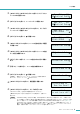
パネル操作 5. [▲INC/YES]/[▼DEC/NO] ボタンを押して、ストアしたい アンプの IDを選択します。 6. [NEXT]ボタンを押して、シーンナンバーに移動します。 7. [ ▲ INC/YES]/[ ▼DEC/NO] ボタンを押して、ストアする シーンナンバーを選択します。 8. [NEXT]ボタンを押して、 に移動します。 9. [▲INC/YES] ボタンを押して、シーンの名前を設定する画面 に移動します。 10. [▲INC/YES]/[▼DEC/NO] ボタンを押して、シーンの名前 の1文字目を編集します。 11. [NEXT] ボタンを押して、シーンの名前の次の文字に移動し ます。 12. 手順 10と11を繰り返し、シーンの名前を編集します。 13. [NEXT]ボタンを押して、 NOTE に移動します。 ・ 表示だけのパラメーターや、リアルタイムに変更が反映され るパラメーターには、 が表示されません。 14. [▲INC/YES] ボタンを押して、確認画面に移動します。 15.
パネル操作 シーン(「1.Scene」) 指定したアンプのシーンをリコールしたりストアしたりします。 1.Scene å Recall ■ シーンをリコールする(「1.
パネル操作 アンプのコントロール(「2.Amp Control」) ACD1 に接続されているアンプをコントロールします。 2.Amp Control å Standby ■ 電源のオン/スタンバイ(「2.Amp Control」→「Standby」) 指定したアンプの電源をオンまたはスタンバイに切り替えます。 パラメーター 範囲 Amp ID: 01 å Standby 説明 Amp ID 00 〜 39, ALL 電源を切り替えるアンプの IDを選択します。 「ALL」を選択すると、全アンプの電 源を指定した状態に切り替えます。 電源状態 Standby/On 電源状態を選択します。 NOTE ・ [Amp ID]で「ALL」を選択した場合、電源状態に「Some Standby」と表示されるときがあります。 これは電源がオ ンのアンプと電源がスタンバイのアンプが混在していることを意味します。 ■ ミュート(「2.
パネル操作 アンプの出力モニター (「3.Output Monitor」) ACD1 に接続されたアンプの出力レベルを表示します。 3.Output Monitor å ■ アンプの出力(「3.Output Monitor」) 指定したアンプの出力レベルをチャンネルごとに表示します。 パラメーター 範囲 Amp ID: A~B~ 01 å 説明 Amp ID 00 〜 39 出力レベルを表示させるアンプの IDを選択します。 レベル 0 0dBu未満のときは、メーターに表示されません。 1 0 〜 6dBu 2 6 〜 16dBu 3 16 〜 22dBu 4 22 〜 28dBu 5 28 〜 34dBu 6 34 〜 41dBu 7 41dBu〜 デバイス設定(「4.Device Setup」) ネットワークに接続された ACD1や ACD1 に接続されたアンプを識別 するための設定をします。 4.Device Setup å Device ID ■ Device IDの設定(「4.
パネル操作 ■ Identify(「4.Device Setup」→「Identify」) Amp Editorで対応する ACD1の「Identify」アイコンを点滅させます。 Identify ON å パラメーター Identify 範囲 ON/OFF 説明 [ON] にするとAmp Editor 上の対応するACD1 の「Identify」アイコンが点灯しま す。[OFF]にすると解除されます。 ユーティリティ (「5.Utility」) ACD1 の汎用的な設定をしたり、情報の確認をします。 5.Utility å Battery ■ バックアップバッテリーの確認(「5.
パネル操作 ■ LCD バックライト(「5.Utility」→「LCD Backlight」) ACD1 のLCDバックライトの点灯状態を設定します。 パラメーター LCD Backlight 範囲 LCD Backlight ON å 説明 ON 常時点灯します。 Auto OFF 自動的に消灯します。 パネル操作をした場合には点灯し、操作してから 10 秒経つと自動的に消灯します。 ■ パネル操作の制限(「5.
パネル操作 ■ EMGコマンドによるシーンリコールの許可(「5.
パネル操作 ■ GPI INのキャリブレーション(「5.Utility」→「GPI Calibration」) [GPI IN] 端子の入力電圧の検出範囲を調節(キャリブレーション )しま Port No.: 3 Min:3.4V->4.2V å す。 パラメーター 範囲 説明 Port No. 1 〜4 キャリブレーションする [GPI IN]端子のポートを選択します。 最小値 /最大値設定 Min/Max 入力電圧の最小値 (Min)を設定するのか、最大値 (Max)を設定するのか選択します。 電圧値 -- 入力電圧を表示します。 「−>」記号の左側が設定されている電圧 ( 最大値/ 最小値 )、右側が現在の入力電圧 です。確定すると、現在の入力電圧が最大値 / 最小値に設定されます。 ネットワークの設定(「6.Network Setup」) ACD1 のネットワークの設定をします。 6.Network Setup å IP Address Mode ■ IP アドレスのモード設定(「6.
パネル操作 ■ 外部コントローラーのポート設定 (「6.Network Setup」→「IP Ctrl Port #」) AMXや Crestronなどの外部機器からACD1 をコントロールするとき IP Ctrl Port # 49153 å に使用するポート番号を設定します。 パラメーター ポート番号 範囲 49153〜 50049 ポート番号 (16進数 ) ACD1 のポート番号を設定します。同じポート番号を使用する他の機器(ACD1 以 外 )がある場合は、ポート番号を変更してください。 ACD1の初期化 ACD1 の内蔵メモリーを初期化できます。 注意 ・ 内蔵メモリーを初期化すると、それまでメモリー内に保存されていた内容( アンプごとのシーン、ACD1の設定 )が失われます。 以下の操作は慎重に行なってください。 1. ACD1の電源をオフにします。 2. [BACK]ボタンを押しながら電源をオンにします。 3.
端子の結線について ACD1のリアパネルにある [GPI]端子と [FAULT OUTPUT]端子の結線について説明します。 ユーロブロックプラグの取り付け方法 必ず付属のユーロブロックコネクターをお使いください。紛失した場合は、取扱説明書巻末に記載されているヤマハ修 理ご相談センターにお問い合わせください。 ● ケーブルの処理 約5mm ・ユーロブロックプラグに取り付けるケーブルは、図のようにむき出して、より線で 配線してください。また、ユーロブロックでの配線は、ケーブルの重さや振動によ る金属疲労により、より線が切れやすくなる場合があります。ラックマウント時 は、できる限り束線バーなどを使用してケーブルを結束して固定してください。 1.3mm 以下 ・可搬設備などで頻繁に抜き差しされる場合は、絶縁スリーブ付き棒端子の使用を 約 5mm 推奨します。棒端子のコンダクター部は、外径 1.3mm 以下で、長さ約5mm の もの (Phoenix Contact社製 AI0,5-6WHなど )をご使用ください。 注意 ・ より線を使用する場合は、より線にはんだめっきしないでください。 1.
端子の結線について GPI端子 リアパネルの [GPI]端子に GPI(General Purpose Interface)機器 ( コントローラーなど) を接続します。 GPI を使い、外部機器と制御信号を入出力します。 ACD1 には4 ポートの入力と 4ポートの出力があります。 GND OUT(出力 ) GND IN(入力 ) 電源 ・ +V 端子の出力電圧は5V です。取り出せる電流は合計で最大 100mA です。 ・ IN端子は 0V 〜5V 間の電圧を検知します。 ・ OUT 端子はオープンコレクター出力です。印加できる電圧は最大+12V です。 ・ 流せる電流は1ポート当たり、最大 75mAです。 ・ パラメーターの割り当てなどの設定は、Amp Editorを使用します。 ・ [GPI]端子には、ユーロブロックプラグを使用します。 ユーロブロックプラグの接続方法は「ユーロブロックプラグの取り付け方法」(18 ページ) をご覧ください。 NOTE ・ Amp Editorで各入出力チャンネルを設定することにより、接続した GPI外部機器からのシーンリコールや任意のパ ラメーターの変更
端子の結線について FAULT OUTPUT端子 リアパネルの [FAULT OUTPUT]端子にランプなどを接続して、異常発生を通知 したりします。 [FAULT OUTPUT]端子は NO(Normally Open) とC(Common)、NC(Normally Close)から構成されています。[FAULT OUTPUT]端子はリレー回路で、以下の ように動作します。 正常時 異常時 電源オフ時 NO Open Closed Closed NC Closed Open Open [FAULT OUTPUT]端子に使用されているリレー接点の定格負荷は、抵抗負荷にて 1A、DC 30Vです。この値を超え る負荷をかけないようにしてください。 [FAULT OUTPUT]端子の設定は、Amp Editorを使用します。 [FAULT OUTPUT]端子には、ユーロブロックプラグを使用します。ユーロブロックプラグの接続方法は「ユーロブ ロックプラグの取り付け方法」(18 ページ) をご覧ください。 NOTE ・ Amp Editorの[Device Setup] メニュー → [Al
資料 メッセージ一覧 ACD1 のディスプレイに表示されるメッセージとその対策方法は以下のとおりです。アラートメッセージについては、 「Amp Editor 取扱説明書」をご参照ください。 メッセージ 対策方法 Panel locked! 誤操作を防ぐために、パネルロック設定でパネル操作がロックされています。 パネルロックを一時的に解除する場合は、[ ▲INC/YES]/[ ▼ DEC/NO]ボタンの両方を 3 秒以上押しま す。パネルロックを無効にする場合は、一時的に解除した状態で、「5.Utility」→「Panel Operation」 をNormalに設定してください。 Parameter locked! 誤操作を防ぐために、パネルロック設定でパラメーター編集がロックされています。 パネルロックを一時的に解除する場合は、[ ▲INC/YES]/[ ▼ DEC/NO]ボタンの両方を 3 秒以上押しま す。パネルロックを無効にする場合は、一時的に解除した状態で、「5.
資料 困ったときは(トラブルシューティング) 症状 考えられる原因 対策方法 ACD1に保存されていたシー ン情報がすべて消えてしまっ た ACD1 のデータ保存中に電源が落とされ た 再度、Amp Editorと同期して Amp Editor から設定情 報を送信してください。 内蔵バッテリーが消耗した 「5.Utility」→「Battery」でバッテリーの状態を確認 し、「Low Battery」または「No Battery」と表示さ れた場合、ACD1 取扱説明書の巻末のヤマハ修理ご相 談センターにバックアップバッテリーの交換をご依頼 ください。 パラメーターが変更できない パネルロックがかかっている 「5.
資料 コントロールI/O 入出力端子 フォーマット *1 MONITOR/REMOTE ― ― RS-485 RS-485 IN ― 0 〜5 V OUT ― Open Collector +V ― 5V DATA PORT *2 GPI *3 レベル FAULT OUTPUT *4 NETWORK ― ― IEEE 802.3 10Base-T/100Base-TX 仕様コネクター D-SUB 15P( メス) × 8 RJ-45 ユーロブロック (3.
資料 480 362 (1) 44 3 354 (5) 寸法図 単位:mm * 仕様および外観は、改良のため予告なく変更することがあります。 24 ACD1 リファレンスマニュアル
U.R.G.