R PDM-1 INPUT INPUT SURROUND VOL VOL N R PICTURE PICTURE PICTURE POS.
Table of Contents Important Safety Notice .............................................. 4 Safety Precautions ...................................................... 5 Accessories ................................................................. 7 Accessories Supply .................................................... 7 Optional Accessories ................................................. 7 Remote Control Batteries ........................................... 8 Connections ...................................
Important Safety Notice WARNING: To prevent damage which may result in fire or shock hazard, do not expose this appliance to rain or moisture. Do not place containers with water (flower vase, cups, cosmetics, etc.) above the set. (including on shelves above, etc.) WARNING: 1) To prevent electric shock, do not remove cover. No user serviceable parts inside. Refer servicing to qualified service personnel. 2) Do not remove the earthing pin on the power plug.
Safety Precautions WARNING Setup This plasma display is for use only with the following optional accessories. Use with any other type of optional accessories may cause instability which could result in the possibility of injury. PDS-150 • Pedestal .......................................... .......................... Wall Mounting Unit PWK-150 • .........................................
Safety Precautions If problems occur during use If a problem occurs (such as no picture or no sound), or if smoke or an abnormal odour starts to come out from the plasma display, immediately unplug the power cord plug from the wall outlet. If you continue to use the plasma display in this condition, fire or electric shock could result. After checking that the smoke has stopped, contact your local Yamaha dealer so that the necessary repairs can be made.
Accessories Accessories Supply Check that you have the accessories and items shown Remote Control Transmitter Batteries for the Remote Control Transmitter (2 × R6 Size) Fixing bands 2 pcs AC cord (Australia) Ferrite core (small size) × 1 INPUT SURROUND VOL N R PICTURE SOUND PICTURE POS.
Remote Control Batteries Requires two R6 batteries. 1. Turn the transmitter face down. Press and slide off the battery cover. 2. Install the batteries as shown in the battery compartment. (Polarity + or – must match the markings in the compartment.) 3. Replace the cover and slide in reverse until the lock snaps. Two "R6" size Helpful Hint: For frequent remote control users, replace old batteries with Alkaline batteries for longer life.
Connections AC cord connection (see page 18) – Cable fixing bands Secure any excess cables with bands, as required. To secure cables connected to Terminals, wrap the cable fixing band around them then pass the pointed end through the locking block, as shown in the figure. While ensuring there is sufficient slack in cables to minimize stress (especially in the power cord), firmly bind all cables with the supplied fixing band. Pass the attached cable fixing band through the clip as shown in the figure.
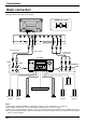
Connections Basic connection (Example) When connecting an AV amplifier S VIDEO 4 pin socket AUDIO VIDEO S VIDEO Chrominance earth Luminance in Chrominance in L R L R Luminance earth AUDIO HD VD AV IN PR/CR/R PB/CB/B Y/G COMPONENT/RGB IN Video pin cable S Video cable Component Video cable AV amplifier VOLUME INPUT SELECTOR VIDEO S VIDEO INPUT MODE STANDBY /ON SPEAKERS A B 6CH INPUT PROGRAM STEREO FM/AM PRESET /TUNING A/B/C/D/E PRESET /TUNING EDIT EFFECT BASS BALANCE T
Connections Speaker Terminals connection When you do not use an AV amplifier, connect the speakers directly with the speaker terminals of the plasma display. Refer to the speaker’s Installation Manual for details on speaker installation. When connecting the speakers, be sure to use only the optional accessory speakers. Speakers (Optional accessories) 1 3 2 1 Remove the tubes from the ends of the speaker cables.
Connections Component/RGB Input connection RGB signal (R, G, B, HD, VD) connection BNC-RCA adaptor plug RGB input to R, G, B, HD, VD sockets Example of input signal source HDTV-compatible VCR 5×BNC RGB cables RGB camera R L AUDIO VD HD PR/CR/R PB/CB/B Y/G COMPONENT/RGB IN AUDIO 2×RCA audio cables Audio input to L/R sockets Computer VD HD R B G Notes: (1) Change the “Component/RGB-in” setting in the “Setup” menu to “RGB”.
Connections PC Input Terminals connection COMPUTER AUDIO PC IN POWER / R - STANDBY INPUT — VOL + G POWER ON Conversion adapter (if necessary) Less than 3" 15/16 (10 cm) Ferrite core (large size) (supplied) D-sub 15p RGB PC cable Ferrite core (small size) (supplied) Less than 3" 15/16 (10 cm) Audio 1/8" (3 mm)Stereo plug Connect a cable which matches the audio output terminal on the computer.
Connections Signal Names for D-sub 15P Connector Pin No. 1 2 3 4 5 11 12 13 14 15 6 7 1 9 10 8 2 3 4 5 Pin Layout for PC Input Terminal Signal Name R G B GND (Ground) GND (Ground) Pin No. Signal Name Pin No.
Connections SERIAL Terminals connection The SERIAL terminal is used when the plasma display is controlled by a computer. 6 1 7 2 8 3 9 4 5 Pin layout for RS-232C Notes: (1) Use the RS-232C cable to connect the computer to the plasma display. (2) The computer shown is for example purposes only. (3) Additional equipment and cables shown are not supplied with this set.
Basic Controls INPUT R - STANDBY G POWER ON — VOL + PDM-1 Main Power On/Off Switch Power Indicator The Power Indicator will light. Power-OFF ..... Indicator not illuminated (The unit will still consume some power as long as the power cord is still inserted into the wall outlet.) Stand-by .... Red Power-ON ...... Green • • • INPUT button (AV(S Video), Component/RGB and PC Mode Selection) Press the “INPUT” button to select AV (S Video), Component/RGB and PC input signal modes sequentially.
Basic Controls SURROUND button (see page 27) INPUT button (AV(S Video), Component/RGB and PC Mode Selection) Press to select AV(S Video), Component/RGB and PC input signal modes sequentially. (see page 19) Sound mute On/Off (see page 26) INPUT INPUT SURROUND Volume Adjustment Press the Volume Up “+” or Down “–” button to increase or decrease the sound volume level.
Power On/Off and input signal selection AC cord connection Connecting the AC cord plug to the plasma display. Power On/Off Connecting the plug to the Wall Outlet Note: Main plug types vary between countries. The power plug shown at left may, therefore, not be the type fitted to your set. R - STANDBY INPUT – VOL switch on the plasma display to turn Press the the set on:Power-On.
Power On/Off and input signal selection Select the input signal INPUT Press the INPUT button to select the input AV signal desired from equipment such as a VCR which has been connected to the plasma display. Input signals will change as follows: R - STANDBY INPUT — VOL + For Component Input (see page 34) G POWER ON AV INPUT — Component PC + VOL For RGB Input (see page 34) AV RGB PC INPUT SURROUND VOL N R Selecting the On-Screen Menu Language SET UP Press to display the Setup menu.
On-Screen Menu Display from Remote Control To Picture adjust menu (see page 28) Press to select each item. Picture Normal Normalise Picture Mode Contrast Brightness Colour Tint Sharpness White balance Advanced settings Normal 20 0 0 0 0 INPUT Normal On SURROUND Setup To Advanced Settings (see page 28, 29) VOL RGB Advanced Settings Normal Normalise Black extension W/B High R W/B High B W/B Low R W/B Low B Gamma Component/RGB-in select N English (UK) OSD Language 0 0 0 0 0 Set up TIMER 2.
On-Screen Menu Display from Remote Control Press to access each adjust screen. R Press the R buttun to return to “Setup” menu. To Signal screen for AV (see page 34, 35) To Signal screen for To Signal screen for RGB Component (see page 35) (see page 36) [ AV ] Signal 3D Y/C Filter (NTSC) Colour system 3:2 Pulldown Aspect Auto (4:3 ) On Auto On 4:3 [ Component ] Signal 3:2 Pulldown [ RGB ] Signal H&V Sync On H-Freq. V-Freq. To Signal screen for PC (see page 36) [ PC ] Signal H&V Sync 31.
ASPECT Controls The plasma display will allow you to enjoy viewing the picture at its maximum size, including wide screen cinema format picture. ASPECT INPUT SURROUND R PICTURE PICTURE POS. /SIZE SOUND SET UP ASPECT OFF TIMER PC 22 4:3 Zoom Auto VOL N ASPECT button The aspect mode changes each time the ASPECT button is pressed. 16 : 9 Just Notes: (1) During RGB and PC input signal modes, the mode switches between “4:3”, “Zoom” and “16:9” only.
ASPECT Controls Picture Mode Explanation 4:3 will display a 4:3 picture at its standard 4:3 size. 4 4:3 4:3 3 4 Zoom mode magnifies the central section of the picture. 16 Zoom Zoom 3 4 9 16:9 will display the picture at its maximum size but with sight elongation.
Adjusting Picture Pos./Size Adjusting screen 1 PICTURE POS. /SIZE Press to display the Picture Pos./Size menu. INPUT SURROUND 2 Press to select H-Pos/H-Size/V-Pos/VSize/Clock Phase. VOL R N PICTURE During “AV(S Video)” and During “RGB” and “PC” input “Component” input signal modes. signal modes. Picture Pos./Size Normalise H-Pos H-Size V-Pos V-Size Normal 3 PICTURE POS. /SIZE SOUND SET UP ASPECT Picture Pos.
Adjusting Picture Pos./Size When the Position Left “ ” button is pressed. When the Position Right “ ” button is pressed. When the Position Left “ ” button is pressed. When the Position Right “ ” button is pressed. When the Position Left “ ” button is pressed. When the Position Right “ ” button is pressed. When the Position Left “ ” button is pressed. When the Position Right “ ” button is pressed.
Sound Adjustment 1 SOUND Press to display the Sound menu. INPUT SURROUND 2 VOL Select to adjust each item. R N Press to select the desired adjustment menu. Select the desired level by listening to the sound. PICTURE SOUND SET UP PICTURE POS S Bass Adjusts low sounds Treble Adjusts high sounds Balance Adjusts left and right volumes Sound Normalise Sound Mode Bass Treble Balance Surround Normal Normal Normal 0 0 0 On Auto Emits the original sound.
Surround Controls SURROUND INPUT SURROUND Button The benefits of surround sound are enormous. You can be completely enveloped in sound; just as if you were at a concert hall or cinema. The surround setting switches on and off each time the SURROUND button is pressed. On SURROUND Off VOL N R PICTURE SOUND SET UP Surround PICTURE POS. /SIZE ASPECT On Note: The surround settings are memorized separately for each Sound mode.
Picture Adjustments 1 2 PICTURE Picture Press to display the Picture menu. Normal Normalise Picture Mode Contrast Brightness Colour Tint Sharpness White balance Advanced Settings Select to adjust each item. Press to select the menu to adjust. Normal 20 0 0 0 0 Normal On Select the desired level by looking at the picture behind the menu. Press the left modes.
Picture Adjustments Item Effect Adjustments Contrast Less More Brightness Darker Brighter Adjusts for easier viewing of dark pictures such as night scenes and black hair. Adjusts colour saturation. Colour Less Tint (NTSC only) Selects the proper brightness and density for the room. More Adjust for nice skin colour. Reddish Greenish Adjusts picture sharpness. Sharpness Less More Notes: (1) “Colour” and “Tint” settings cannot be adjusted for “RGB” and “PC” input signal modes.
Set up TIMER The timer can switch the plasma display On or Off. Before attempting Timer Set, confirm the PRESENT TIME and adjust if necessary. Then set POWER ON Time / POWER OFF Time. Display the Set up TIMER screen 1 SET UP Setup Press to display the Setup menu screen. INPUT Component/RGB-in select RGB Signal Screensaver SURROUND N PICTURE Press to select Set up TIMER. 2 VOL English (UK) OSD Language Set up TIMER R SOUND Press to display the Set up TIMER screen.
Set up TIMER TIMER Set Press to select POWER ON Time/POWER OFF Time. 1 Set up TIMER PRESENT TIME POWER ON Function POWER ON Time POWER OFF Function POWER OFF Time 0:52 Off 0:00 Off 0:00 Press to display the POWER ON Setup/ POWER OFF Setup screen. 2 Press to select Hours Adjustment/ Minutes Adjustment. POWER ON Setup Press to adjust each time. POWER ON Time Hours Adjustment Minutes Adjustment 0 : 52 00 52 POWER OFF Setup 3 Press to complete POWER ON Time/ POWER OFF Time.
Screensaver (For preventing after-images) Do not display a still picture, especially in 4:3 mode, for any length of time. If the display must remain on, a Screensaver should be used. 1 SET UP Press to display the Setup menu screen. Setup Component/RGB-in select RGB 2 Signal Screensaver Press to select the Screensaver. English (UK) OSD Language Set up TIMER Press to select the Screensaver screen. Reversal / Scroll selection 3 Press to select the Function. Press to select the desired function.
Screensaver (For preventing after-images ) Setup of Screensaver Time Press to select Start Time/ Finish Time (When Time Designation is selected). Press to select Periodic Time/ Operating Time (When Interval is selected). 5 Press to select each Time Adjustment screen.
Setup for Input Signals Component/RGB-in select Select to match the signals from the source connected to the Componen/RGB input terminals. “Component” Y, PB, PR signals R, G, B, HD, VD signals “RGB” 1 SET UP Press to display the Setup menu screen. INPUT Press to select the “Component/RGB-in select”. 2 SURROUND Press to select the desired mode. VOL R N Setup Component/RGB-in select RGB Signal Screensaver English (UK) OSD Language PICTURE SOUND Set up TIMER SET UP Component PICTURE POS.
Setup for Input Signals Colour system / Aspect Auto Select Signal from the “Setup” menu during AV(S Video) input signal mode. (“Signal [AV]” menu is displayed.) Setup Component/RGB-in select RGB Press to select the “Colour system” or “Aspect Auto”. Signal Screensaver English (UK) OSD Language Press to select each functions.
Setup for Input Signals Sync Select Signal from the “Setup” menu during RGB or PC input signal mode. Setup Component/RGB-in select RGB Signal Screensaver Press to adjust. English (UK) OSD Language Set up TIMER Press (ACTION) button [ RGB ] Signal H&V Sync H-Freq. V-Freq. R 31.5 kHz 60.0 Hz Press to exit from adjust mode. [ PC ] Signal H&V Sync H-Freq. V-Freq. 31.5 kHz 60.0 Hz Setting RGB sync signal: Confirm that the input is set to RGB input (this setting is valid only for RGB input).
Troubleshooting Before you call for service, determine the symptoms and make a few simple checks as shown below. Symptoms Picture Checks Sound Interference Noisy Sound Electrical Appliances Cars/Motorcycles Fluorescent light Normal Picture No Sound Volume (Check whether the mute function has been activated on the remote control.
Specifications PDM-1 Power Source Power Consumption 220 - 240 V AC, 50/60 Hz Normal use Stand-by condition Power off condition 495 W 3.0 W 1.7 W plasma display panel Drive method AC type 50-inch, 16:9 aspect ratio 3000:1 Contrast Ratio Screen size 1,106 mm (W) × 622 mm (H) × 1,269 mm (diagonal) No.
Specifications PDM-1 Accessories Supplied Remote Control Transmitter Batteries Fixing bands Ferrite core EUR646528 2 × R6 Size 2 pcs (small size) × 1, (large size) × 2 Optional Supplied Speakers Pedestal Wall Mounting Unit SP-PDM1 PDS-150 PWK-150 1,210 mm × 724 mm × 98 mm Dimensions (W × H × D) 98 mm 724 mm 1,210 mm POWER / R - STANDBY INPUT — VOL + G POWER ON Mass (Weight) approx. 43.0 kg net (main unit only) Notes: (1) Design and specifications are subject to change without notice.
YAMAHA YAMAHA YAMAHA YAMAHA YAMAHA YAMAHA YAMAHA ELECTRONICS CORPORATION, USA 6660 ORANGETHORPE AVE., BUENA PARK, CALIF. 90620, U.S.A. CANADA MUSIC LTD. 135 MILNER AVE., SCARBOROUGH, ONTARIO M1S 3R1, CANADA ELECTRONIK EUROPA G.m.b.H. SIEMENSSTR. 22-34, 25462 RELLINGEN BEI HAMBURG, F.R. OF GERMANY ELECTRONIQUE FRANCE S.A. RUE AMBROISE CROIZAT BP70 CROISSY-BEAUBOURG 77312 MARNE-LA-VALLEE CEDEX02, FRANCE ELECTRONICS (UK) LTD. YAMAHA HOUSE, 200 RICKMANSWORTH ROAD WATFORD, HERTS WD1 7JS, ENGLAND SCANDINAVIA A.