
Operating instructions


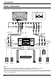
Table Of Contents
- Table of Contents
- Important Safety Notice
- Safety Precautions
- Accessories
- Accessories Supply
- Optional Accessories
- Remote Control Batteries
- Connections
- Basic connection
- Speaker Terminals connection
- Component/RGB Input connection
- PC Input Terminals connection
- SERIAL Terminals connection
- Basic Controls
- Power On/Off and input signal selection
- AC cord connection
- Power On/Off
- Select the input signal
- Selecting the On-Screen Menu Language
- On-Screen Menu Display from Remote Control
- ASPECT Controls
- Adjusting Picture Pos./Size
- Sound Adjustment
- Mute
- Surround Controls
- Picture Adjustments
- Advanced Settings
- Set up TIMER
- PRESENT TIME Set
- TIMER Set
- Screensaver (For preventing after-images)
- Setup of Screensaver Time
- Side Panel Adjustment
- Setup for Input Signals
- Component/RGB-in select
- 3D Y/C Filter – For NTSC AV images
- Colour system / Aspect Auto
- 3:2 Pulldown
- Sync
- H-Freq. (kHz) / V-Freq. (Hz)
- Troubleshooting
- Specifications

9
Connections
P
R
/C
R
/R
P
B
/C
B
/B Y/G
COMPONENT/RGB INAV IN
VD
HD
S VIDEOVIDEO
R
L
AUDIO
R
L
AUDIO
AUDIO
To tighten:
To loosen:
Push
the catch
Pull
Pull
PC IN SERIAL
1 2
– Cable fixing bands
Secure any excess cables with bands, as required.
From EXIT monitor Terminal
on Computer (see page 13)
COMPONENT/RGB IN and Audio IN
Terminals (see page 10, 11, 12)
AV IN Terminals
(see page 10, 11)
From SERIAL Terminal on
Computer (see page 15)
Pass the attached cable
fixing band through the clip
as shown in the figure.
To secure cables connected to Terminals, wrap the cable
fixing band around them then pass the pointed end
through the locking block, as shown in the figure.
While ensuring there is sufficient slack in cables to
minimize stress (especially in the power cord), firmly
bind all cables with the supplied fixing band.
AC cord connection (see page 18)