Owner’s Manual
FCC INFORMATION (U.S.A.) 1. IMPORTANT NOTICE: DO NOT MODIFY THIS UNIT! This product, when installed as indicated in the instructions contained in this manual, meets FCC requirements. Modifications not expressly approved by Yamaha may void your authority, granted by the FCC, to use the product. 2. IMPORTANT: When connecting this product to accessories and/or another product use only high quality shielded cables. Cable/s supplied with this product MUST be used. Follow all installation instructions.
Important Read the following before operating the CS1D Warnings Operating Notes • Do not allow water to enter this unit or allow the unit to become wet. Fire or electrical shock may result. • Connect this unit’s power cord only to an AC outlet of the type stated in this Owner’s Manual or as marked on the unit. Failure to do so is a fire and electrical shock hazard. • Do not place heavy objects, including this unit, on top of the power cord. A damaged power cord is a fire and electrical shock hazard.
Important • Do not wipe the disc with chemicals or detergents. • Do not bend or drop the disc. • Use an air duster or cleaner to remove dust. Vigorously rubbing the surface of the disc with a dry cloth may scratch the disc. • Do not write on the disc or affix labels to it. • Keep water droplets or condensation off of the label surface. • Yamaha Corporation makes no guarantee of a disc that is rendered unreadable due to careless handling.
Operating Manual
Operating Manual (Start-up)
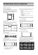
Contents Introduction . . . . . . . . . . . . . . . . . . . . . . . . . . . . . . . . . . . . . . . . .1 About the “CS1D Operating Manual (Start-up)” . . . . . . . . . . . . . . . . . . . . . . . . . . 1 Printing conventions in “CS1D Operating Manual (Start-up)”. . . . . . . . . . . . . . . . 1 Introducing the various components . . . . . . . . . . . . . . . . . . . . .2 Terms used in the “CS1D Operating Manual (Start-up)” . . . . . . . . . . . . . . . . . . . . 4 Connections (Standard mode). . . . . . .
Contents Basic settings (Mirror mode) . . . . . . . . . . . . . . . . . . . . . . . . . . 26 Selecting the operation mode (Mirror mode) . . . . . . . . . . . . . . . . . . . . . . . . . . . 26 Setting the word clock (Mirror mode) . . . . . . . . . . . . . . . . . . . . . . . . . . . . . . . . . 28 Checking the operation of input units . . . . . . . . . . . . . . . . . . . 30 Preparations for checking . . . . . . . . . . . . . . . . . . . . . . . . . . . . . . . . . . . . . . . . . . .
Introduction About the “CS1D Operating Manual (Start-up)” The “CS1D Operating Manual (Start-up)” is an introductory manual that explains how to connect the various components of the PM1D system and verify that the PM1D system is operating correctly.
Introducing the various components The PM1D system consists of the following types of components. (The components that are actually included will differ depending on your system.) Engine (DSP1D-EX {DSP1D}) This is the DSP unit that performs the majority of the audio processing in the PM1D system, such as audio signal input/output, mixing, and effects. There are two models of engine: the 96 channel DSP1D-EX, and the 48 channel DSP1D.
Introducing the various components It is not possible to install and use a total of five or more AP8AD/AP8DA cards. Also, if you are using AP8AD/AP8DA cards simultaneously with MY8AD/MY4-AD/MY4-DA cards, there are restrictions on the number of cards, as described below. Never exceed the allowable number of cards, since attempting to use a greater number of cards than allowed may damage the DIO8 due to excessive current.
CS1D Operating Manual (Start-up) Terms used in the “CS1D Operating Manual (Start-up)” Of the specialized terms used in operating the CS1D, this section will explain the terms that appear in “CS1D Operating Manual (Start-up).” For a more detailed explanation of terms, refer to “CS1D Operating Manual (Basic Operation).” [CURSOR] switches Track pad Display Data entry block [ENTER] switches • Display This refers to the LCD display located in the upper center of the CS1D console.
Introducing the various components • Drag “Drag” refers to the action of placing the pointer over a specific object on the screen, and holding down the left or right switch while you slide your finger left/right/up/down across the track pad. This action is used to continuously adjust a knob or slider in the screen, or to move a specific item to another location. Hint As an alternative way to perform this action, you can use a mouse connected to the MOUSE connector of the CS1D.
Connections (Standard mode) x1 DSP This section explains connections for Standard mode, in which one console (CS1D) is connected to one engine (DSP1DEX {DSP1D}). Connecting the console and engine (Standard mode) The following diagram shows typical connections between the console and engine for Standard mode.
Connections (Standard mode) Hint Hint If both digital input/output connectors 1 and 2 are connected, connector 1 will be given priority when the power is turned on. If both control input/output connectors 1 and 2 are connected, connector 1 will be given priority when the power is turned on. If the word clock stops being supplied from either connector 1 or 2 (whichever is the currently-used connector), the receiving device will automatically switch to the other connector.
CS1D Operating Manual (Start-up) Connecting an analog input/output unit to the engine (Standard mode) The following diagram shows a common way of making connections between the engine and analog input/output units for Standard mode.
Connections (Standard mode) Connecting a digital input/output unit to the engine (Standard mode) When connecting a DIO8 digital input/output unit to the engine in Standard mode, the method will depend on whether you use only slots 1–4 (of the DIO8’s slots 1–8) or slots 1–4 as well as slots 5–8. 1 If input/output cards are installed only in DIO8 slots 1–4 The following diagram shows example connections for when input/output cards are connected only to slots 1–4 of the DIO8.
Connections (Mirror mode) x2 DSP This section explains connections for Mirror mode, in which one console (CS1D) is connected to two engines (DSP1DEX {DSP1D}). Connecting the console and engines (Mirror mode) The following diagram shows typical connections between the console and engines for Mirror mode.
Connections (Mirror mode) Hint If both digital input/output connectors 1 and 2 are connected, connector 1 will be given priority when the power is turned on. If the word clock stops being supplied from either connector 1 or 2 (whichever is the currently-used connector), the receiving device will automatically switch to the other connector.
CS1D Operating Manual (Start-up) Connecting an analog input/output unit to the engines (Mirror mode) The following diagram shows a common way of making connections between the engine and analog input/output units for Mirror mode.
Connections (Mirror mode) Connecting a digital input/output unit to the engines (Mirror mode) The following diagram shows the usual method of connecting the engines to a digital input/output unit in Mirror mode.
Turning on the power and verifying the connections Here’s how to turn on the power of the various components in the PM1D system, and verify that the devices are connected correctly. Before you continue with the following procedure, connect the various components of the system as described on pages 6–13.
Turning on the power and verifying the connections If the opening screen is followed by the “VERSION CHECK” popup window, it is possible that the PM1D system version is incorrect. Please unify the software version of all connected devices. For the procedure, refer to the explanation within the included PM1D System Software disc. Hint Normally, the display will show the screen that was accessed last when the power was turned off.
CS1D Operating Manual (Start-up) Checking the analog input unit (Standard mode) If the AI8 input unit is correctly connected to the engine, the INPUT UNIT ID indicator of the AI8 will show the ID number of that unit (i.e., the number of the INPUT connector on the engine to which the AI8 is connected). INPUT UNIT ID ID number of the AI8 (when the AI8 is connected to the INPUT 1 connector of the engine) 1 2 3 4 5 6 7 8 INPUT UNIT NO.
Turning on the power and verifying the connections Checking the analog output unit (Standard mode) If the AO8 analog output unit is correctly connected to the engine, the OUTPUT UNIT ID indicator of the AO8 will display the ID number of that unit (i.e., the number of the OUTPUT connector on the engine to which the AO8 is connected). If multiple connectors are connected, the number of the connector used by the engine to transmit and receive control signals will be displayed.
CS1D Operating Manual (Start-up) Checking the status of each device (Mirror mode) x2 DSP Here’s how to check the connection status of each device when using the PM1D system in Mirror mode. Engines (Mirror mode) The front panel of each DSP1D-EX {DSP1D} engine displays the following information.
Turning on the power and verifying the connections Checking the analog input unit (Mirror mode) If the AI8 analog input unit is correctly connected to the engine in Mirror mode, the INPUT UNIT ID indicator of the AI8 will show the ID number of that unit (i.e., the number of the INPUT connector on the engine to which the AI8 is connected), and the dot ( . ) will light on both sides of the ID number.
CS1D Operating Manual (Start-up) Checking the analog output unit (Mirror mode) In Mirror mode if the AO8 is correctly connected to the engine, the OUTPUT UNIT ID indicator of the AO8 will show the ID number of that unit (i.e., the number of the OUTPUT connector on the engine to which the AO8 is connected), and the dot ( . ) will light on both sides of the ID number. ID number of the AO8 (when the AO8 is connected to the OUTPUT 2 connector of the engine) 1 2 3 4 5 6 7 8 OUTPUT UNIT NO.
Turning on the power and verifying the connections Checking the digital input/output unit (Mirror mode) If the output unit and the engine are correctly connected in Mirror mode and the PORT B SELECTOR of the DIO8 is in the 5-8 position, the I/O UNIT ID indicator will show the ID number of that unit (i.e., the number of the OUTPUT connector on the engine to which the INPUT A connector of the DIO8 is connected), and a dot ( . ) will be displayed at each side of the number.
Basic settings (Standard mode) x1 DSP When starting up the PM1D system for the first time, you will need to select the operation mode of the PM1D (which is what determines the system configuration and how the components are connected to each other), and set the word clock that will be shared by the entire system. Once these settings have been made, the PM1D system will automatically remember them. (However if you modify the configuration of the system, you may need to make settings again.
Basic settings (Standard mode) This is the SYSTEM CONNECTION screen, in which you can check the connection status of the various components, and select the operation mode. 2. Click the button located at the right of “OPERATION MODE.” The OPERATION MODE window will appear, in which you can select the operation mode. Verify that the OPERATION MODE field indicates “CONSOLE x1 <-> ENGINE x1.” When you perform this switch, the word clock will be reset.
CS1D Operating Manual (Start-up) Setting the word clock (Standard mode) In order for the PM1D system to function, word clock (audio system clock) synchronization must be established between all devices of the system. In this screen you can specify the word clock that will operate the PM1D system. In general, the frequency of this clock is referred to as the sampling rate or sampling frequency. [Procedure] 1. In the LCD FUNCTION ACCESS block, press the [SYS/W.
Basic settings (Standard mode) Hint When the ADVANCED button is on, you can make more detailed word clock settings. 3. Click one of the following buttons to select the word clock source as the word clock master. In Standard mode you can select one of the following three choices as the word clock. When you change the word clock settings, noise may be heard from the output jacks of the CS1D and AO8, particularly if an MY8-AT digital I/O card is installed in the DIO8.
Basic settings (Mirror mode) x2 DSP This section explains how to select the operation mode and word clock master when using the PM1D system in Mirror mode. Selecting the operation mode (Mirror mode) [Procedure] 1. In the LCD FUNCTION ACCESS block, press the [SYS/W.CLOCK] switch several times to access the following screen. LCD FUNCTION ACCESS block [SYS/W.CLOCK] switch This is the SYSTEM CONNECTION screen, in which you can check the connection status of each device, and select the operation mode.
Basic settings (Mirror mode) 2. Click the button located at the right of “OPERATION MODE.” The OPERATION MODE window will appear, in which you can select the operation mode. ATION MODE field indicates “CONSOLE x1 <-> ENGINE x2 (Mirror Mode).” When you perform this switch, the word clock will be reset. At this time, noise may be produced from the output jacks of the CS1D or AO8 (in particular if an MY8-AT digital I/O card is installed in the DIO8).
CS1D Operating Manual (Start-up) Setting the word clock (Mirror mode) This section explains how to check whether the word clock settings are appropriate when using the PM1D system in mirror mode. [Procedure] 1. In the LCD FUNCTION ACCESS block, press the [SYS/W.CLOCK] switch several times to access the following screen. LCD FUNCTION ACCESS block [SYS/W.CLOCK] switch Settings for the word clock of the PM1D system are made in this screen. 2.
Basic settings (Mirror mode) 3. Make sure that the master word clock and the word clock input select are set as follows. MASTER CLOCK SELECT • The W.CLOCK of the engine or console is on WORD CLOCK INPUT SELECT Console W.CLOCK IN Engine A/B W.CLOCK IN Each unit W.CLOCK IN Word clock settings will automatically be as shown above.
Checking the operation of input units This section explains how to check the operation of an input unit connected to the DSP1D-EX {DSP1D} engine. The general procedure is as follows.
Checking the operation of input units Connect the monitor system In order to check the operation of an input unit, you must connect a monitor system such as powered monitor speakers or a power amp + speaker to the MONITOR OUT A jacks located on the rear panel of the CS1D console. (Since the purpose of this is to check the operation, high power monitors are not necessary.) If you will be monitoring through headphones, connect them to the PHONES MONITOR A jack located on the front panel of the CS1D console.
Connect an input source Connect one of the following input sources according to the type of input unit or card that you wish to check. • To check a mic/line input card (LMY2-ML) installed in the AI8 Connect a line output device such as a CD player or DAT recorder to input jacks 1A and 2A of the LMY2ML. 1 2 3 4 5 6 7 8 INPUT UNIT NO.
Checking the operation of input units Patch the input unit to an input channel Simply connecting a source to an input unit does not cause that signal to be input to the PM1D system. In order to send signals to the PM1D system, you must assign (patch) the input jacks of the input unit to input channels of the PM1D system. This operation is performed within the display of the CS1D console. [Procedure] 1. Turn on the power in the order of PM1D system → monitor system. 2.
CS1D Operating Manual (Start-up) Patch source input jack. From the top row, the display shows the type and ID of the input unit, the number of the slot in which the input card is installed, and the number of the channel (jack) within the card. Number of the patch destination input channel. In this grid, input jacks (horizontal rows) can be patched to input channels (vertical columns). A ● symbol is displayed to indicate a currently-patched grid location.
Checking the operation of input units Using the switches of the console Using the track pad of the console 1. Use the [CURSOR] switches in the data entry block to move the cursor (the red frame) in the display to the desired grid. 1. Use the track pad to move the cursor to the desired grid. (The cursor will change to the shape of a finger.) Data entry block Data entry block [CURSOR] switch Track pad [ENTER] switch 2. Press the [ENTER] switch to make a ● symbol appear. 2.
CS1D Operating Manual (Start-up) Monitor the input signal After you have patched an input source to an input channel, press the [CUE] switch for that input channel and check whether it is output from the MONITOR OUT jacks. [Procedure] 1. Play back the input source, and check that the meter LEDs light for input channels 1/49 and 2/50 in INPUT block 1 of the console.
Checking the operation of input units Hint When monitoring through the MONITOR A headphone jack, raise the MONITOR A PHONES [LEVEL] volume (located in the MONITOR A section of the MASTER block) to an appropriate level. If you are now able to monitor the signal, you have verified that the input unit/card to which the source is connected is operating normally. 4. As necessary, perform the same operational check for other input units or cards.
Checking the operation of an output unit This section explains the procedure for checking the operation of an output unit connected to the DSP1D-EX {DSP1D} engine. The general procedure is as follows.
Checking the operation of an output unit Connect the monitor system In order to check the operation of an analog output unit, you will need to connect a monitor system such as a set of powered speakers or a power amp + speakers to a DA card (LMY4-DA) installed in the AO8 analog output unit. 1 2 3 4 5 6 7 8 OUTPUT UNIT NO.
CS1D Operating Manual (Start-up) Connect an input source As a sound source for checking, connect a line output device such as a CD player or DAT recorder to an input unit. 1 2 3 4 5 6 7 8 INPUT UNIT NO.
Checking the operation of an output unit Patch the input unit to an input channel Patch the input jack to which you connected the input source to input channels 1/2. For details of the procedure, refer to page 33. [Procedure] 1. Turn on the power in the order of the PM1D system → monitor system. 2. In the LCD FUNCTION ACCESS block, press the INPUT [PATCH] switch several times to access the following screen. LCD FUNCTION ACCESS block INPUT [PATCH] switch 3.
CS1D Operating Manual (Start-up) Patch the STEREO A channel to an output unit Similarly to the case for an input unit, outputting a signal from the PM1D system requires more than simply connecting your monitor system to an output unit. In order to output a signal, you must also assign (patch) an output channel (MIX channel, MATRIX channel, STEREO A/B channel) of the PM1D system to the jacks of an output unit. This action is performed within the display of the CS1D console.
Checking the operation of an output unit Patch destination output jacks. From the top, this area shows the type and ID of the output unit, the number of the slot in which the output card is installed, and the channel (jack) number within the card. Patch source output channels. In this grid, output jacks (horizontal rows) can be patched to output channels (vertical columns). A ● symbol will be displayed for currently-patched grids.
CS1D Operating Manual (Start-up) Send the input signals of input channels 1/2 to the STEREO bus With the operations you have performed up to this point, the signals of the STEREO bus of the PM1D system will be output to the output jacks to which your monitor system is connected. Now we will send the signals of the input source to the STEREO bus to verify that they can be monitored via your monitor system. [Procedure] 1. Play back the input source.
Checking the operation of an output unit 7. In the STEREO OUTPUT block, raise the ST OUTPUT A channel fader. At this time, the STEREO A L/R meters in the meter bridge block will show the output level of the STEREO A channel.
CS1D Operating Manual (Start-up) • Is the Solo function turned on? → If the [SOLO] switch is turned on in the MASTER block CUE section, and the [CUE] button of any channel is turned on, the signals of the other channels will be muted. Turn off the [SOLO] switch (“CS1D Reference Manual (Hardware)” →p.81). Turn off the power You have now finished the system check of the “CS1D Operating Manual (Start-up).
Operating Manual (Basic Operation)
Contents Chapter 1. Introduction . . . . . . . . . . . . . . . . . . . . . . . . . . . . . . . .1 About the “CS1D Operation Manual (Basic Operation)” . . . . . . . . . . . . . . . . . . . . 1 Printing conventions in the “CS1D Operation Manual (Basic Operation)” . . . . . . . . . 1 Overview of the PM1D system . . . . . . . . . . . . . . . . . . . . . . . . . . . . . . . . . . . . . . . . . 2 Full-digital/separate type SR mixing system . . . . . . . . . . . . . . . . . . . . . . . . . . . .
Contents Basic operation INPUT blocks/ST IN block . . . . . . . . . . . . . . . . . . . . . . . . . . . . . . INPUT block/ST IN block controls and functions . . . . . . . . . . . . . . . . . . . . . . . Head amp settings . . . . . . . . . . . . . . . . . . . . . . . . . . . . . . . . . . . . . . . . . . . . . Sending a signal from an input channel to a STEREO bus . . . . . . . . . . . . . . . . Sending a signal from an input channel to a MIX bus . . . . . . . . . . . . . . . . . . . Pairing settings . . .
Contents Inserting into an output channel . . . . . . . . . . . . . . . . . . . . . . . . . . . . . . . . . . . 89 Direct out . . . . . . . . . . . . . . . . . . . . . . . . . . . . . . . . . . . . . . . . . . . . . . . . . . . . . . . . 91 Direct out connections . . . . . . . . . . . . . . . . . . . . . . . . . . . . . . . . . . . . . . . . . . 91 Directly outputting an input channel signal . . . . . . . . . . . . . . . . . . . . . . . . . . . 91 Chapter 7. DCA groups/Mute groups . . . . . . . . . . . .
Contents Chapter 11. Talkback/Oscillator . . . . . . . . . . . . . . . . . . . . . . . 120 Talkback . . . . . . . . . . . . . . . . . . . . . . . . . . . . . . . . . . . . . . . . . . . . . . . . . . . . . . . . 120 Oscillator . . . . . . . . . . . . . . . . . . . . . . . . . . . . . . . . . . . . . . . . . . . . . . . . . . . . . . . 122 Chapter 12. Internal effects . . . . . . . . . . . . . . . . . . . . . . . . . . 124 About the internal effects of the PM1D system . . . . . . . . . . . . . . . . . . .
Chapter 1. Introduction About the “CS1D Operation Manual (Basic Operation)” The “CS1D Operation Manual (Basic Operation)” explains basic operation of the PM1D system, such as connecting the input sources and playback system, operating the CS1D console, and using the display of the CS1D to make various settings. • The “CS1D Operation Manual (Basic Operation)” assumes that the various components of the PM1D system have been connected and are operating correctly.
CS1D Operating Manual (Basic Operation) Overview of the PM1D system The PM1D system is a full-digital SR mixing system that consists of a CS1D console, PW1D power supply, DSP1D-EX {DSP1D} DSP unit(s), AI8 analog input unit(s), AO8 analog output unit(s), DIO8 digital input/output unit(s), and input/output cards. This section describes the ways in which the PM1D system differs from conventional analog mixing consoles.
Chapter 1. Introduction • Analog output unit (AO8) This output unit outputs analog audio signals from the engine. The AO8 has eight slots, with eight LMY4-DA DA cards installed at the factory.
CS1D Operating Manual (Basic Operation) Signal flow in the PM1D system The following diagram shows the general signal flow within the PM1D system. Mic 1 Line device 2 3 4 5 6 7 Speaker system foldback 8 1 2 3 4 5 6 7 8 INPUT UNIT NO. PHANTOM MASTER ON +48V OUTPUT UNIT NO.
Chapter 1.
CS1D Operating Manual (Basic Operation) Number of inputs/outputs and channel structure The DSP1D-EX {DSP1D} engine provides INPUT connectors 1–10 for connecting input units, and OUTPUT connectors 1–6 for connecting output units. x1 DSP When the PM1D system is used in Standard mode, up to ten input units (maximum of 320 input connectors) and up to six output units (maximum of 192 output connectors) are connected to one engine.
Chapter 1. Introduction In either mode, the input connectors of an input unit must be assigned (patched) in the CS1D display to an input channel in order to be used. Similarly, in order to use the output connectors of an output unit, you must assign them in the display to an output channel (MIX channel, MATRIX channel, STEREO A/B channel).
CS1D Operating Manual (Basic Operation) MIX buses/MATRIX buses The PM1D system can send the input channel signals to MIX buses 1–48. The signals sent to a MIX bus is routed through a MIX channel that provides EQ, comp, and delay, and is output from the respective connector that is patched to MIX 1–48. At this time, you can choose to either fix the signal levels that are output from the input channels (FIX mode) or allow them to vary (VARI mode).
Chapter 2. The user interfaces of the CS1D This chapter introduces the various user interfaces that control the software of the CS1D console, and explains how to use them. About the user interfaces The PM1D system is designed so that basic parameters such as channel adjustments and mixing can be controlled using only the faders and encoders on the top panel of the CS1D. However if you wish to make more detailed settings, you will need to access a specific function and edit the parameter value in software.
CS1D Operating Manual (Basic Operation) • Text input box These boxes are used to input characters/numerals/ symbols when assigning a name to a channel or scene, etc. • Character palette This is a virtual keyboard used to input characters/ numerals/symbols into a text input box. • Scroll bar When one screen is insufficient to display all of the items, this bar is used to access the portion that is currently not shown.
Chapter 2. The user interfaces of the CS1D User interface on the top panel of the CS1D The top panel of the CS1D provides the following controls used for operations in the display. LCD FUNCTION ACCESS block The LCD FUNCTION ACCESS block contains switches used to access the desired function or screen in the display. LCD FUNCTION ACCESS block 1 2 3 1 Global functions These switches access functions that affect the entire PM1D system.
CS1D Operating Manual (Basic Operation) Data entry block The data entry block contains controllers used to modify the settings and values in the display. 3 [SHIFT/GRAB] switch When the cursor in the display is located at a knobtype parameter that has a broad range of adjustment, you can hold down this switch and use the [DEC/ CANCEL]/[INC/OK] switches or rotate the [DATA] encoder to change the parameter value in larger steps.
Chapter 2.
CS1D Operating Manual (Basic Operation) Various basic operations This section explains the basic operations performed in the CS1D display. In general, operations in the CS1D software will consist of combinations of these actions. Click “Click” is the action of moving the pointer to a specific item in the screen, and pressing the left or right switch of the track pad (or if using an external mouse, pressing the left or right mouse button).
Chapter 2. The user interfaces of the CS1D Drag and drop “Drag and drop” is the action of moving the pointer to a specific item in the screen, dragging it to another location in the screen, and then releasing your finger. Drag and drop is used (for example) to copy EQ or dynamics processor settings to another channel. Scroll When the number of items for display is greater than can be shown in a single screen, you can drag the box within the scroll bar to view the hidden portion.
CS1D Operating Manual (Basic Operation) Accessing the desired screen There are two ways to access the desired function/screen in the display. Using the LCD FUNCTION ACCESS block Using the buttons within the display [Procedure] [Procedure] 1. Of the switches in the LCD FUNCTION ACCESS block, press the switch for the desired function. The last-operated screen of the corresponding function will be accessed. 1. In any screen, click the MENU button.
Chapter 2. The user interfaces of the CS1D Button operations Buttons within the display are used to turn specific parameters on/off, or to choose one of multiple choices. Buttons can be operated in the following ways. Using the track pad (mouse) Using the data entry block switches /keyboard [Procedure] [Procedure] 1. Drag the track pad (mouse) to move the pointer to the desired button. 1. Use the [CURSOR] switches (or the arrow keys of the keyboard) to move the cursor to the desired button.
CS1D Operating Manual (Basic Operation) Moving the cursor Here’s how to move the cursor (red box) in order to select the display parameter that you wish to edit. Moving the cursor Moving the cursor from a scroll window [Procedure] [Procedure] 1. Press a CURSOR [▲]/[▼]/[√]/[®] switch. The cursor in the display will move in the direction of the switch you pressed. However, the cursor will not move if no parameter exists in the direction of that switch. 1.
Chapter 2. The user interfaces of the CS1D Adjusting the value of a knob or fader Knobs and faders within the display are used to adjust the value of specific parameters. Knobs and faders can be adjusted in the following ways. Using the track pad (mouse) [Procedure] 1. Move the pointer to the desired knob/fader, and use the left or right switch of the track pad (mouse) to click the knob/fader. The cursor will move to that location. 2.
CS1D Operating Manual (Basic Operation) Assigning a name The PM1D system allows you to assign names (long name, short name) to individual channels, and to assign titles to scenes and libraries. For example, the screen shown below is the LIBRARY STORE popup window in which you can name and store a library. Characters can be input in this screen in the following ways. • LIBRARY STORE popup window 1. Use the text palette (or the keyboard) to input characters.
Chapter 2. The user interfaces of the CS1D • √ ® buttons.......Move the highlighted area to left or right. • PASTE button ....The text string that had been copied to the buffer by the COPY button will be pasted. • COPY button .....The specified text string will be copied from the text box into the buffer. • CAPS LOCK button Switch between uppercase and lowercase alphabetical characters. When this button is on, uppercase characters can be input. 3. When you have input the name, click the STORE button.
Chapter 3. Audio connections and patching This chapter explains how to connect input/output devices such as mics and speaker systems to the input/output units and to the CS1D console, and patch them to input channels and output channels. The “CS1D Operation Manual (Basic Operation)” assumes that the components of the PM1D system are connected appropriately, and that all components are operating correctly.
Chapter 3. Audio connections and patching • AD card (LMY4-AD) The LMY4-AD provides four channels of XLR-3-31 (balanced) input jacks that can be used simultaneously. • LMY4-AD connections 1 2 3 4 5 6 7 8 INPUT UNIT NO. PHANTOM MASTER AI8 analog input unit ON +48V OFF POWER ON/ OFF ANALOG INPUT BOX SIGNAL SIGNAL SIGNAL SIGNAL CH4 AD CARD MODEL LMY4-AD CH2 CH3 Rhythm machine ANALOG IN CH1 AD-Platine (LMY4-AD) Synthesizer The pin wiring is as follows.
CS1D Operating Manual (Basic Operation) Audio connections for an analog output unit An LMY4-DA DA card installed in the AO8 analog output unit provides four channels of XLR-3-32 (balanced) output jacks. • LMY4-DA connections 1 2 3 4 5 6 7 8 OUTPUT UNIT NO. INPUT SELECTOR AO8 analog output unit A B POWER ON/ OFF ANALOG OUTPUT BOX SIGNAL ANALOG OUT SIGNAL SIGNAL DA CARD MODEL LMY4-DA SIGNAL CH4 CH3 CH2 CH1 LMY4-DA DA-Platine Speaker system The pin wiring is as follows.
Chapter 3. Audio connections and patching Audio connections for a digital input/output unit The DIO8 digital input/output unit can accommodate up to eight digital I/O cards or analog I/O cards, according to your system. The following diagrams show examples of connecting the DIO8 to digital recorders in ADAT, Tascam, and AES/EBU formats.
CS1D Operating Manual (Basic Operation) Audio connections for the console In the PM1D system, most of the signal processing is performed in the input/output units and in the engine, and the console simply controls their operation. However as exceptions, the CS1D also has the following input/output jacks. • 2-TRACK IN DIGITAL AES/EBU jacks (1–6) These are AES/EBU (XLR-3-31) jacks for inputting AES/EBU format digital sources from an external device such as a CD player or DAT recorder.
Chapter 3. Audio connections and patching • TALKBACK IN 1 jack (top panel) • TALKBACK IN 2 jack (rear panel) These are XLR-3-31 (balanced) jacks for connecting talkback mics. These two jacks can be used simultaneously.
CS1D Operating Manual (Basic Operation) Patching Simply connecting an external device to an input/output unit does not cause the signal to be input to (or output from) the engine. In order to transfer signals to and from the engine, you must assign (patch) each connector of the input/output unit to a channel of the PM1D system.
Chapter 3. Audio connections and patching 2. Use the horizontal scroll bar to access the patch source input unit. The horizontal axis of the screen shows the input unit ID number/card slot number/input jack channel number. To view a unit/card/input jack that is not currently visible, use the horizontal scroll bar. From above, this indicates the type and number of input unit/ card slot number/input jack channel number/number of input channels patched to that jack.
CS1D Operating Manual (Basic Operation) Hint The short name you assign to each channel will be displayed in various screens of the display and in the [NAME] indicator of the CS1D console. 9. As necessary, assign names to other channels as well. Hint If you wish to assign names to numerous channels at once, it is convenient to use the IN PATCH function NAME screen. (“CS1D Reference Manual (Software)” →p.
Chapter 3. Audio connections and patching 2. Use the vertical scroll bar to access the patch source output channel. The vertical axis of the screen shows the patch source MIX channel (MIX 1–48), MATRIX channel (MTRX 1–24), or STEREO A/B channel (ST AL/AR, ST BL/ BR). To view a portion that is not currently visible, use the vertical scroll bar. From above, this indicates the type and number of output unit/card slot number/output jack channel number.
Chapter 4. Basic operation for input channels This chapter explains basic operation for input channels/ST IN channels. About input channels Blocks used to control input channels On the PM1D system, you can use 96 {48} monaural input channels and 8 {4} stereo ST IN channels. A signal patched to one of these input channels passes through the internal four-band EQ/compressor/gate, and is sent to the STEREO bus or MIX bus. The following blocks on the CS1D console are used to control input channels.
Chapter 4. Basic operation for input channels Changing the channel assignments When the PM1D system is in its default state, INPUT blocks 1–4 are assigned input channels 1–12, 13–24, 25–36, and 37–48 respectively. Similarly, ST IN channels 1–4 are assigned to the ST IN block. However, you can change these assignments by using the SELECTED INPUT CHANNEL block MODULE [FLIP] switch and the MASTER block GLOBAL LAYER [1-48]/[49-96] switches, as described below.
CS1D Operating Manual (Basic Operation) Basic operation INPUT blocks/ST IN block This section explains basic input channel operation using the INPUT blocks/ST IN block. Since multiple channels are controlled simultaneously in the INPUT blocks/ST IN block, the number of controllable parameters is limited to the necessary minimum. This means that there are some parameters that cannot be controlled unless you use the display or the SELECTED INPUT CHANNEL block.
Chapter 4. Basic operation for input channels ST IN block ST IN STATUS [L]/[R] LEDs These LEDs indicate which channel (L or R) is currently displayed by this ST IN channel module. ST IN [MIX] encoder and LEDs This encoder sets the send level of the signal that is sent from the ST IN channel to a VARI type MIX bus. The peripheral LEDs will light to indicate the approximate current value. ST IN MIX [ON] LED This LED indicates the on/off status of the signal that is sent from the ST IN channel to the MIX bus.
CS1D Operating Manual (Basic Operation) Head amp settings For channels to which a mic/line amp card (LMY2-ML) has been patched, you must complete various settings for the head amp (e.g., select input jacks A/B, turn phantom power on/off) before you continue. Hint This section explains the procedure for an input channel. If you are using a ST IN channel, head amp settings must be made separately for L and R. Use the ST IN SEL [L]/[R] switches to select each channel and make settings. [Procedure] 1.
Chapter 4. Basic operation for input channels If you wish to use phantom power, you must also turn on the +48V switch located on the front panel of the AI8 input unit. If this switch is off, no phantom power will be supplied to the cards installed in that unit. 4. While watching the level meter, drag the on-screen GAIN knob to adjust the input sensitivity of the channel. The GAIN knob adjusts the input sensitivity of the head amp.
CS1D Operating Manual (Basic Operation) Sending a signal from an input channel to a STEREO bus Here’s how to use the INPUT block/ST IN block to send an input channel signal to a STEREO bus. Hint The procedure described here uses the example of an input channel, but virtually the same procedure applies to ST IN channels as well. [Procedure] 1. Make sure that an input source is correctly patched to the input channel, and that the head amp is set appropriately. 2.
Chapter 4. Basic operation for input channels Sending a signal from an input channel to a MIX bus Here’s how to use the INPUT block/ST IN block to send an input channel signal to a MIX bus. Hint If the send destination is a MIX bus, the type of MIX bus (FIX or VARI) that you wish to use must first be selected in the display. Then you can set the send level for each channel. MIX buses set to FIX type can be used as group buses, and MIX buses set to VARI type can be used as AUX buses.
CS1D Operating Manual (Basic Operation) 2. Use the on-screen FIX/VARI buttons to select either FIX type or VARI type for adjacent odd-numbered → even-numbered MIX buses. When you switch between FIX type and VARI type, the screen and signal flow will change as follows.
Chapter 4. Basic operation for input channels 3. Use the on-screen ON/OFF buttons to switch the signal sent from each input channel to the MIX bus on/off. In the case of a FIX type MIX bus, this is all you need to do for the nominal-level signal of each channel to be sent to the corresponding MIX bus. Hint The signal that is sent from each input channel to the MIX bus cannot be switched on/off by operations in the INPUT block/ST IN block.
CS1D Operating Manual (Basic Operation) • INPUT block MIX SEND section MIX SEND [▼/DEC]/[▲/INC] switch Select one of MIX buses 1–48 to control. MIX SEND [LOCAL] switch and LED This specifies whether the MIX bus number currently selected in the INPUT block will be linked with other INPUT blocks ([LOCAL] switch = off) or can be switched independently of other INPUT blocks ([LOCAL] switch = on). MIX SEND [NUMBER] indicator This displays the short name and number of the currently selected MIX bus.
Chapter 4. Basic operation for input channels Pairing settings Monaural input channels can be paired so that their principal parameters are linked. [Procedure] 1. For adjacent odd-numbered → even-numbered input channels, hold down one of the [SEL] switches and press the other [SEL] switch. The direction in which the channel parameters are copied will depend on the order in which the [SEL] switches are pressed.
CS1D Operating Manual (Basic Operation) Basic operation in the SELECTED INPUT CHANNEL block Here we will explain how to control an input channel using the SELECTED INPUT CHANNEL block. The SELECTED INPUT CHANNEL block controls only the currently selected channel. In exchange for being limited to only one channel, you can manually control virtually all of the mix parameters for the input channel, from head amp settings to EQ/ compressor/gate settings, and sends to the STEREO bus and MIX buses.
Chapter 4. Basic operation for input channels PAIR PAIR EQ ON EQUALIZER PAIR STEREO section Switch the signal sent from the currently selected channel to the STEREO bus on/off and adjust its panning. STEREO PAIR GAIN section Adjust the input sensitivity of the head amp for channels to which a mic/line input card (LMY2-ML) has been patched. CHANNEL SELECT section Select/view the channel that will be controlled by the SELECTED INPUT CHANNEL block.
CS1D Operating Manual (Basic Operation) Head amp settings Here’s how to use the SELECTED INPUT CHANNEL block to make head amp settings for an input channel to which a mic/line input card (LMY2-ML) has been patched. Hint Even for ST IN channels or input channels that have been paired, head amp settings must be made independently. Select each channel in turn, and make settings for it. [Procedure] 1.
Chapter 4. Basic operation for input channels 4. While watching the level meter in the fader section of the SELECTED INPUT CHANNEL block, use the GAIN section [GAIN] encoder to adjust the input sensitivity of the channel. The peripheral LEDs of the encoder will indicate the approximate value. This may not be operable, depending on the type of input unit that is patched.
CS1D Operating Manual (Basic Operation) 6. In the STEREO OUTPUT block, turn on the STEREO A [ON] or STEREO B [ON] switch. STEREO OUTPUT block STEREO A [ON] switch ON TO MTRX ON STEREO B [ON] switch MONO SEL SEL INS INS 10 10 5 5 0 0 5 5 10 10 20 20 RCL MUTE 30 SAFE 30 40 40 50 50 60 60 RCL MUTE SAFE STEREO A/ STEREO B faders 7. In the STEREO OUTPUT block, raise the STEREO A or STEREO B fader.
Chapter 4. Basic operation for input channels Sending signals from an input channel to a MIX bus Here’s how to use the SELECTED INPUT CHANNEL block to send an input channel signal to a MIX bus. By using the SELECTED INPUT CHANNEL block, you can simultaneously control the signals that are sent from a specific input channel to multiple MIX buses. [Procedure] 2. Use the INPUT block [SEL] switch or the ST IN block SEL [L]/[R] switch to select the input channel from which the signal will be sent. 3.
CS1D Operating Manual (Basic Operation) 5. Use the MIX SEND section [PRE] switches to select the location (PRE/POST) from which the signal will be sent to VARI type MIX buses. If the PM1D system is in its initial state, the pre-fader signal will be sent to MIX buses whose MIX SEND [PRE] switch LED is lit, and the post-fader signal will be sent to MIX buses for which this switch LED is dark.
Chapter 4. Basic operation for input channels Using the delay By using the DELAY section of the SELECTED INPUT CHANNEL block, you can delay the input signal of an input channel by a specified interval. For example, this is useful when you wish to compensate for time differences between mic placed at a distance from each other. [Procedure] 1. Use the INPUT block [SEL] switches or the ST IN block [L]/[R] switches to select the input channel that you wish to control. 2.
CS1D Operating Manual (Basic Operation) Using the compressor By using the COMPRESSOR section of the SELECTED INPUT CHANNEL block, you can manually operate nearly all of the compressor parameters. Hint The compressors provided by the PM1D system allow you to choose from three types: COMP (compressor), EXPANDER, and COMPANDER. However, the choice of type cannot be made from the top panel.
Chapter 4. Basic operation for input channels [Procedure] 1. Use the INPUT block [SEL] switches or the ST IN block [L]/[R] switches to select the input channel that you wish to control. 2. In the LCD FUNCTION ACCESS block, press the INPUT [GATE/COMP] switch several times to access the following COMP PRM screen. • INPUT COMP LIBRARY popup window Library list This list shows the input compressor data that has been stored in memory. The highlighted row is currently selected for operations.
CS1D Operating Manual (Basic Operation) 6. In the COMPRESSOR section of the SELECTED INPUT CHANNEL block, turn on the COMPRESSOR [ON] switch. The compressor will be turned on for the corresponding channel. 7. Use the knobs and encoders in the COMPRESSOR section to adjust parameters such as ATTACK, RELEASE, THRESHOLD LEVEL, and GAIN. Hint For details on the parameters of each type, refer to “CS1D Reference Manual (Appendices)” (→p.11).
Chapter 4. Basic operation for input channels Using the noise gate As with the compressor, most parameters of the built-in noise gate of the PM1D system can be controlled manually by using the NOISE GATE section of the SELECTED INPUT CHANNEL block. Hint The noise gate of the PM1D system allows you to select one of two types: GATE or DUCKING. However, the type cannot be selected by operations in the front panel.
CS1D Operating Manual (Basic Operation) [Procedure] 1. Use the INPUT block [SEL] switches or the ST IN block [L]/[R] switches to select the input channel that you wish to control. 2. In the LCD FUNCTION ACCESS block, press the INPUT [GATE/COMP] switch several times to access the following GATE PRM screen. • INPUT GATE LIBRARY popup window Library list This shows a list of the input noise gate data that has been stored in memory. The highlighted row is currently selected for operations.
Chapter 4. Basic operation for input channels Hint For details on the parameters of each type, refer to “CS1D Reference Manual (Appendices)” (→p.16). You can also make settings so that the relevant screen appears when you operate the NOISE GATE section. This setting is made in the UTILITY function PREFERENCE screen (“CS1D Reference Manual (Software)” →p.37). Using the 4 band EQ/HPF Here’s how to use the EQUALIZER section of the SELECTED INPUT CHANNEL block to control the 4 band EQ and the HPF.
CS1D Operating Manual (Basic Operation) [Procedure] 1. Use the INPUT block [SEL] switches or the ST IN block [L]/[R] switches to select the input channel that you wish to control. 2. In the EQUALIZER section of the SELECTED INPUT CHANNEL block, turn on the [EQ ON] switch. The 4 band EQ of the corresponding channel will be turned on. 3. For each band, use the [Q] encoder, [F] encoder, and [GAIN] encoder to set the steepness, center frequency, and gain respectively.
Chapter 5. Basic operation for output channels This chapter explains basic operation for MIX channels, MATRIX channels, and STEREO A/B channels. About the output channels Blocks used to control the output channels The PM1D system provides MIX channels 1–48, MATRIX channels 1–24, and the STEREO A/B channels as output channels for MIX buses 1–48, MATRIX buses 1–24, and the STEREO bus.
CS1D Operating Manual (Basic Operation) Switching the channel assignments When the PM1D system is in its initial state, MIX channels 1–24 are assigned to the MIX OUTPUT block. However, this assignment can be changed as follows by the MIX LAYER [1-24]/[25-48] switches of the MIX OUTPUT block.
Chapter 5. Basic operation for output channels Basic operation of the MIX OUTPUT block This section explains basic operation of the MIX OUTPUT block. Controls and functions of the MIX OUTPUT block MIX [NAME] indicator This shows the short name of the MIX channel. MIX [TO MTRX] switch and LED This is an on/off switch for the signal that is sent from the MIX channel to the MATRIX buses. If this switch is off, no signal will be sent from that MIX channel to any MATRIX bus.
CS1D Operating Manual (Basic Operation) Sending a signal from a MIX channel to an output unit Here’s how the signal sent from an input channel to the MIX bus can be output from the output unit patched to the corresponding MIX channel. [Procedure] 1. Make sure that an appropriate signal is being sent from the input channel to the MIX bus. Also make sure that a valid output unit is patched to the corresponding MIX channel. 2.
Chapter 5. Basic operation for output channels Sending a signal from a MIX channel to a MATRIX bus Here’s how the signal sent from an input channel to a MIX bus can be output to a MATRIX bus. [Procedure] 1. Make sure that an appropriate signal is being sent from an input channel to a MIX bus. • Detail of MATRIX/ST ROUTING Enable/cancel pairing for two adjacent odd-numbered → even-numbered MATRIX buses. 2.
CS1D Operating Manual (Basic Operation) 5. In the screen, drag the knob located at the intersection of the source MIX channel and the destination MATRIX bus to adjust the level of the signal sent from each MIX channel to the MATRIX bus. The current value is shown in the numerical box below the knob. 7. In the MATRIX OUTPUT block, turn on the MATRIX [ON] switch for the appropriate MATRIX channel. This parameter can be controlled only in the display. 6.
Chapter 5. Basic operation for output channels Sending a signal from a MIX channel to the STEREO bus Here’s how the signal sent from an input channel to a MIX bus can be output to the STEREO bus. [Procedure] 1. Make sure that an appropriate signal is being sent from an input channel to the corresponding MIX bus. 2. In the MIX OUTPUT block, turn on the MIX [ON] switch. 3. Turn on the MIX [TO ST] switch. If MIX [TO ST] switch is off, the signal from that MIX channel will not be sent to the STEREO bus. 4.
CS1D Operating Manual (Basic Operation) Pairing MIX channels Adjacent odd-numbered → even-numbered MIX channels can be paired. All parameters except for pan and delay will be linked for the two paired channels. [Procedure] MIX1 SEND LEVEL INPUT CHANNEL FADER …… PAN ON MIX1 (VARI) LEVEL When MIX channels are paired, the functions of the controllers on the CS1D console and the parameters in the display will change as follows.
Chapter 5. Basic operation for output channels ■ MIX OUTPUT block If MIX channels are paired, the left (odd-numbered) encoder will function as a [BAL] encoder to set the volume balance between the two MIX channels, and the right (even-numbered) encoder will function as a [LEVEL] encoder for both MIX channels. The operation of other adjacent odd-numbered → even-numbered switches will also be linked.
CS1D Operating Manual (Basic Operation) ■ CH to MIX screen In the row of paired MIX buses, the PRE buttons and ON/OFF buttons will be consolidated for odd → even numbers. Of the two adjacent odd-numbered → even-numbered knobs of VARI type MIX channels, the left (odd-numbered) knob will function as a PAN knob to set the panning between the two MIX buses, and the right (even-numbered) knob will function as a LEVEL knob for both MIX buses.
Chapter 5. Basic operation for output channels Basic operation of the MATRIX OUTPUT block This section explains basic operation of the MATRIX OUTPUT block. Controls and functions of the MATRIX OUTPUT block MATRIX [NAME] indicator This displays the short name of the MATRIX channel. MATRIX [ON] switch and LED This switch turns the MATRIX channel on/ off. If this switch is off, the signal will not be sent to the output unit patched to the corresponding MATRIX channel.
CS1D Operating Manual (Basic Operation) Hint The detection point (metering point) shown in the meters can be specified in greater detail. For details refer to the section “Setting the metering point” in “Chapter 16. Various settings.” Pairing MATRIX channels Adjacent odd-numbered → even-numbered MATRIX channels can be paired. All parameters except for pan and delay will be linked for the two paired channels. [Procedure] 1.
Chapter 5. Basic operation for output channels • When MATRIX channels are paired • When MATRIX buses are paired PAN knob ON MATRIX channel 2 OUTPUT LEVEL ON PAIR MIX channel 1 →MATRIX buses 1/2 MIX channel 2 →MATRIX buses 1/2 MIX channel 1 →MATRIX buses 1/2 MIX channel 2 →MATRIX buses 1/2 MATRIX1 MATRIX2 MATRIX channels 1/2 BALANCE LEVEL knob MIX CHANNEL 1 MATRIX CHANNEL OUTPUT LEVEL FADER BALANCE ON MATRIX 1 ON ON OUTPUT PATCH MATRIX 2 to MATRIX 1/2 PAN ON LEVEL …… 2.
CS1D Operating Manual (Basic Operation) Basic operation of the STEREO OUTPUT block This section explains basic operation of the STEREO OUTPUT block. Controls and functions of the STEREO OUTPUT block STEREO A [TO MTRX] switch and LED (STEREO A channel only) This is an on/off switch for the signal sent from the STEREO A channel to the MATRIX buses. If this switch is off, no signal will be sent from the STEREO A channel to any MATRIX bus.
Chapter 5. Basic operation for output channels Sending a signal from a STEREO A/B channel to an output unit Here’s how a signal sent from an input channel or MIX channel to the STEREO bus can be output from an output unit patched to a STEREO A/B channel. [Procedure] 1. Make sure that an appropriate signal is being sent from the channels to the STEREO bus. Also make sure that a valid output unit is patched to a STEREO A/B channel. 2.
CS1D Operating Manual (Basic Operation) Basic operation of the SELECTED OUTPUT CHANNEL block This section explains how to use the SELECTED OUTPUT CHANNEL block to control an output channel. In the SELECTED OUTPUT CHANNEL block, you can select one channel from the MIX channels, MATRIX channels, or L/R of the STEREO A/B channels, and use the EQ and compressor to process the signal before outputting it to an output unit or to another bus.
Chapter 5. Basic operation for output channels EQUALIZER ON DCA section Assign the currently selected channel to the desired DCA group. OUTPUT section Control the output level and on/off status of the signal sent from the currently selected channel to the output unit or STEREO bus/MATRIX bus. DCA SAFE section Temporarily exclude the currently selected select from Scene Recall operations or Mute Group operations.
CS1D Operating Manual (Basic Operation) • When a MATRIX channel is selected The [MATRIX] switch LED will light, and the [NUMBER] indicator will show a number in the range of 1–24. • When a MIX channel is selected The [MIX] switch LED will light, and the [NUMBER] indicator will show a number in the range of 1–48. STEREO OUTPUT block Hint ON TO MTRX It is also possible to select a channel by using the SELECTED OUTPUT CHANNEL block CHANNEL SELECT [▼/DEC]/[▲/INC] switches.
Chapter 5. Basic operation for output channels Sending a signal from a MIX channel to a MATRIX bus/STEREO bus Here’s how you can use the SELECTED OUTPUT CHANNEL block to send a MIX channel signal to the STEREO bus or a MATRIX bus. [Procedure] 1. Use the [SEL] switches of the MIX OUTPUT block to select the MIX channel that you wish to control. • MATRIX/ST ROUTING screen (MATRIX/ST function) 2.
CS1D Operating Manual (Basic Operation) 8. If you are sending the MIX channel signal to the STEREO bus, use the [PAN/BAL] encoder located in the OUTPUT section to adjust the pan. If a MIX channel is selected in the SELECTED OUTPUT CHANNEL block and the OUTPUT [TO ST] switch is on, the OUTPUT [TO ST PAN] switch LED will light. This indicates that you can use the OUTPUT [PAN/BAL] encoder to adjust the pan of the signal that is sent from the MIX channel to the STEREO bus.
Chapter 5. Basic operation for output channels Sending a signal from the STEREO A channel to the MATRIX bus Here’s how to use the SELECTED OUTPUT CHANNEL block to send the signal of the STEREO A channel to a MATRIX bus. [Procedure] 1. Use the STEREO A [SEL] switch of the STEREO OUTPUT block to select the STEREO A channel. • MATRIX/ST ROUTING screen (MATRIX/ST function) 2. In the OUTPUT section of the SELECTED OUTPUT CHANNEL block, turn on the [TO MTRX] switch.
CS1D Operating Manual (Basic Operation) Delay settings You can use the DELAY section of the SELECTED OUTPUT CHANNEL block to delay the output signal of a desired output channel by a fixed time. For example, this provides a convenient way to compensate between speaker systems that are located at a distance from each other. [Procedure] 1. Use the [SEL] switches of the MIX OUTPUT block, MATRIX OUTPUT block, or STEREO OUTPUT block to select the output channel that you wish to control. 2.
Chapter 5. Basic operation for output channels Compressor settings You can use the COMPRESSOR section of the SELECTED OUTPUT CHANNEL block to manually control almost all of the compressor parameters. Hint The compressors of the PM1D system allow you to select one of three types: COMP (compressor), EXPANDER, and COMPANDER. However, it is not possible to select the type by operations on the top panel.
CS1D Operating Manual (Basic Operation) [Procedure] 1. Press a [SEL] switch in the MIX OUTPUT block, MATRIX OUTPUT block, or STEREO OUTPUT block to select the output channel that you wish to control. 2. In the LCD FUNCTION ACCESS block, press the OUTPUT [COMP] switch several times to access the following COMP PRM screen. • OUTPUT COMP LIBRARY popup window Library list This is a list of the output compressor data that has been stored in memory. The currently highlighted line is selected for operations.
Chapter 5. Basic operation for output channels 6. In the COMPRESSOR section of the SELECTED OUTPUT CHANNEL block, turn on the COMPRESSOR [ON] switch. The compressor of the corresponding channel will be enabled. 7. Use the knobs and encoders of the COMPRESSOR section to adjust parameters such as ATTACK, RELEASE, THRESHOLD LEVEL, and GAIN. Hint For details on the parameters of each type, refer to “CS1D Reference Manual (Appendices)” (→p.11).
CS1D Operating Manual (Basic Operation) [Procedure] 1. Press a [SEL] switch in the MIX OUTPUT block, MATRIX OUTPUT block, or STEREO OUTPUT block to select the output channel that you wish to control. 2. In the EQUALIZER section of the SELECTED OUTPUT CHANNEL block, turn on the [EQ ON] switch. The 6 band EQ of the corresponding channel will be enabled. 3. For each band, use the [Q] encoder, [FREQUENCY] encoder, and [GAIN] encoder to set the steepness, center frequency, and gain respectively. 4.
Chapter 6. Insert and direct out This chapter explains how external devices such as effect processors can be inserted into a specific channel, and how the signal of an input channel can be directly output from a desired output jack. Insert An external device such as an effect processor can be inserted in an input channel/output channel of the PM1D system.
CS1D Operating Manual (Basic Operation) Inserting into an input channel Here’s how an external device connected to an input/output unit can be inserted into an input channel. [Procedure] • INSERT PATCH screen (IN PATCH function) 1. In the LCD FUNCTION ACCESS block, press the INPUT [PATCH] switch several times to access the following INSERT PATCH screen (IN PATCH function).
Chapter 6. Insert and direct out 4. In the LCD FUNCTION ACCESS block, press the INPUT [PATCH] switch several times to access the following INSERT/DIRECT OUT screen (IN PATCH function). In the INSERT/DIRECT OUT screen (IN PATCH function) you can switch insertion on/off for each input channel. Here you can also select the insert I/O point (the position at which the external device is inserted), and the direct out point (the position from which direct output is taken).
CS1D Operating Manual (Basic Operation) 8. From the 1-24 INS, 25-48 INS, 49-72 INS, 73-96 INS, and ST IN INS tabs, click the tab that contains the channel into which you wish to insert the external device. {On the 48 channel model, the 49-72 INS and 73-96 INS tabs are not valid.} The following items will be displayed, according to the type of input card that was patched to the insert point in step 3.
Chapter 6. Insert and direct out Inserting into an output channel Here’s how an external device can be inserted into an output channel (MIX channel, MATRIX channel, STEREO A/B channel). Most of the steps are the same as for an input channel. [Procedure] 1. In the LCD FUNCTION ACCESS block, press the OUTPUT [PATCH] switch several times to access the following INSERT PATCH screen (OUT PATCH function). 4.
CS1D Operating Manual (Basic Operation) 7. In the LCD FUNCTION ACCESS block, press the OUTPUT [INSERT] switch. The OUT INSERT function screen will appear. This contains mainly preamp settings for the input card that is patched to the insert point.
Chapter 6. Insert and direct out Direct out An input source patched to an input channel can be output directly from a desired output jack without being affected by the STEREO bus or MIX buses. Direct out connections If you wish to directly output a specific signal, you can use an output jack of an output unit as a direct output. • Direct out connection example 1 1 2 3 4 5 6 7 • Direct out connection example 2 8 OUTPUT UNIT NO.
CS1D Operating Manual (Basic Operation) From the top, this shows the type and number of the output unit, the slot number of the card, and the channel number of the output jack. Number of the input channel Name of the input channel To patch the direct out point of a channel to the desired output jack, click this grid to display a “●” symbol. Number of output jacks that are patched to the direct out point of that channel 2.
Chapter 7. DCA groups/Mute groups On the PM1D system, channels can be assigned to a DCA group/mute group to adjust the levels or switch muting on/off for a group of channels. This chapter explains operations for DCA groups and mute groups. DCA groups The PM1D system has 12 DCA groups to which input channels (input channels, ST IN channels) or output channels (MIX channels) can be assigned. By using the DCA faders in the DCA GROUP block of the console, you can control the levels of each DCA group.
CS1D Operating Manual (Basic Operation) INPUT block INPUT block Hint The assignment of input channels/output channels to DCA groups can also be performed within the display (IN DCA/MUTE function DCA ASSIGN screen, OUT DCA/MUTE function DCA ASSIGN screen). MIX OUTPUT block DCA 10 5 0 5 INPUT [DCA] switch DCA 1 2 3 4 5 6 7 8 9 10 11 12 10 10 5 0 5 1 2 3 4 5 6 7 8 9 10 11 12 10 20 30 ST IN block 20 RCL MUTE 30 RCL MUTE • Output channels cannot be assigned to DCA groups 1–8.
Chapter 7. DCA groups/Mute groups Controlling a DCA group By using the DCA faders in the DCA GROUP block of the console, you can control the levels of each DCA group. [Procedure] 1. Assign input channels/output channels to a DCA group. 2. In the DCA GROUP block of the console, turn on the FADER STATUS [DCA] switch (the LED will light). 4. To mute a specific DCA group, press the DCA [MUTE] switch (located in the DCA GROUP block) for that DCA group.
CS1D Operating Manual (Basic Operation) Mute groups The PM1D system provides 12 mute groups, to which the desired input channels (input channels, ST IN channels) or output channels (MIX channels, MATRIX channels) can be assigned. By using the [1]–[12] switches located in the SCENE MEMORY block of the console, you can turning muting on/off for each mute group. Do not confuse “mute groups” with the “DCA group muting” that is controlled by the DCA [MUTE] switches of the DCA GROUP block.
Chapter 7. DCA groups/Mute groups Assigning output channels to a mute group Here’s how to assign an output channel (MIX channel, MATRIX channel) to a mute group. [Procedure] 1. In the LCD FUNCTION ACCESS block, press the OUTPUT [DCA/MUTE] switch several times to access the following MUTE GROUP ASSIGN screen (OUT DCA/MUTE function). 3. In the same way, assign output channels to other mute groups. It is not possible to assign input channels and output channels to the same mute group of mute groups 9–12.
CS1D Operating Manual (Basic Operation) Controlling a mute group By using the SCENE MEMORY [1]–[12] switches in the SCENE MEMORY block of the console, you can switch muting on/off for mute groups 1–12. [Procedure] 1. Assign input channels/output channels to mute groups 1–12. 2. In the LCD FUNCTION ACCESS block, press the INPUT [DCA/MUTE] switch several times to access the MUTE GROUP ASSIGN screen (IN DCA/ MUTE function).
Chapter 7. DCA groups/Mute groups 4. Press a SCENE MEMORY [1]–[12] switch. The LED of the corresponding switch will light, and the mute group assigned to that switch will be muted. (All channels assigned to that group will be in the same state as if their [ON] switches had been turned off.) Hint You can turn on multiple buttons to simultaneously mute two or more mute groups. 5. To turn off muting, press a SCENE MEMORY [1]– [12] switch whose LED is currently lit.
Chapter 8. Scene memory Mix parameters and various settings of the PM1D system can be stored in memory as a scene, and later recalled (loaded). This chapter explains mainly how to perform scene operations using the top panel of the CS1D. Hint It is also possible to store/recall scenes by operations within the display. (By using this method, you can assign names to individual scenes.) For details refer to “CS1D Reference Manual (Software)” (→p.18).
Chapter 8. Scene memory The currently selected scene is shown by the [SCENE NUMBER] indicator located in the SCENE MEMORY block of the console. • Using the SCENE MEMORY [0]–[9] switches to directly input the scene number In this method, you use a three-digit number to specify the scene number. Consecutively input the two-digit integer portion and the one-digit decimal portion. (If the integer portion has only one digit, add a 0 at the beginning.
CS1D Operating Manual (Basic Operation) Scene memory operations Storing a scene Here’s how to store the current mix settings as a scene. We recommend that you store the current state as a scene memory before you turn off the power supply (PW1D). If the current unit connection state differs from the unit connection state the next time the power is turned on, patch settings etc. may be modified.
Chapter 8. Scene memory • If there are any changes in a UNIT, PATCH, or NAME library that is linked to that scene, the popup window for the corresponding library will appear after the SCENE STORE popup window. Store the library as necessary. • If the EVENT RECALLING button is set to “ENABLE” in the TC EVENT screen of MIDI/GPI/ TC functions, pressing the [STORE] switch will produce a message of “TIME CODE ACTIVE! CANNOT STORE!,” and the Store operation cannot be executed.
CS1D Operating Manual (Basic Operation) Using PREVIEW mode The SCENE MEMORY block provides two modes: “NORMAL” mode in which the scene is actually loaded into the system, and “PREVIEW” mode in which only the parameter values are loaded without affecting the internal signal processing of the system. By using PREVIEW mode you can confirm the setting values of a scene in memory, or edit the settings and store them once again. [Procedure] 1.
Chapter 8. Scene memory Directly recalling a scene Frequently-used scenes can be assigned to the SCENE MEMORY [1]–[12] switches of the SCENE MEMORY block, and directly recalled at one touch. [Procedure] 1. In the LCD FUNCTION ACCESS block, press the [SCENE] switch several times to access the following screen. 4. Click the ASSIGN button. The scene you selected in step 3 will be assigned to the switch whose number you selected in step 2. 5.
Chapter 9. Recall safe/Mute safe This chapter explains the “Recall Safe” function that excludes specific channels or parameters from recall operations, and the “Mute Safe” screen that excludes specific channels from mute operations. Recall safe “Recall Safe” is a function that allows you to specify certain channels or parameters to remain unaffected when a scene is recalled.
Chapter 9. Recall safe/Mute safe If Recall Safe is specified for either (not both) the odd-numbered or even-numbered channel of two channels, and you recall a scene in which these two channels are paired, pairing will be forcibly defeated, and the channel that was set to Recall Safe will maintain the state prior to the recall. Using the screen to set/defeat Recall Safe Recall Safe can also be set/cancelled from within the display.
CS1D Operating Manual (Basic Operation) In the case of parameters of which there is only one setting for two adjacent odd-numbered → evennumbered channels (such as the parameters listed below), Recall Safe will be valid only if both channels are set to Recall Safe. 3. To defeat Recall Safe, turn off the button of the corresponding channel/parameter in the RECALL SAFE screen.
Chapter 9. Recall safe/Mute safe Using the screen to set/defeat Mute Safe You can also set/defeat Mute Safe from within the display. This method is convenient when you wish to quickly make settings for multiple channels. [Procedure] 1. To set Mute Safe for input channels, press the INPUT [DCA/MUTE] switch (located in the LCD FUNCTION ACCESS block) several times to access the following MUTE GROUP ASSIGN screen (IN DCA/MUTE function).
Chapter 10. Monitor This chapter explains monitoring functions of the PM1D system such as the MONITOR A/B outputs and the cue/solo functions. Basic operation of the MONITOR A/MONITOR B section About MONITOR A/MONITOR B The PM1D system provides two monitor outputs, MONITOR A and MONITOR B. For each, the monitoring source can be selected and the output level set independently. To control MONITOR A/MONITOR B from the CS1D console, you will use the following sections of the MASTER block.
Chapter 10. Monitor Controls and functions of the MONITOR A/MONITOR B sections The controls and functions of the MONITOR A/MONITOR B sections are explained below. ■ MONITOR A section ■ MONITOR B section MONITOR A SOURCE [2TR IN 1]/ [2TR IN 2]/[ST A]/[ST B]/[DEFINE] switches and LEDs Select the monitor source for the MONITOR A output. The switch LED for the currently selected source will light. (Only one source at a time can be selected.
CS1D Operating Manual (Basic Operation) • Detail of the CUE section 3. Use the buttons arranged in the DEFINE section of the screen to select the source that will be monitored when the SOURCE [DEFINE] switch is pressed. You can select from the following monitor sources. • MIX 1–48 ........... Output signals of MIX buses 1– 48 • MATRIX 1–24.... Output signals of MATRIX buses 1–24 • 2TR IN 3–6 ........ Input signals from 2-TRACK IN DIGITAL jacks 3–6 of the CS1D console Hint CUE ACTIVE LED 2.
Chapter 10. Monitor 7. As necessary, use the DELAY [ON] switch and the DELAY [TIME] encoder to set the dedicated delay for MONITOR A. The [ON] switch at left switches the delay on/off, and the [TIME] encoder at right sets the delay time. The delay time range is 0 msec – 750 msec. 8. If you wish to monitor the MONITOR A output in monaural, turn on the [L MONO] switch or [R MONO] switch.
CS1D Operating Manual (Basic Operation) Hint In the MONITOR B screen you can also use DIRECT IN to directly monitor the signal from a specific input jack. For details refer to “CS1D Reference Manual (Software)”. 4. In the MASTER block MONITOR B section, press one of the SOURCE [2TR IN 1]/[2TR IN 2]/[ST A]/ [ST B]/[MONITOR B]/[DEFINE] switches to select the source that you wish to monitor. The following sources correspond to each switch. • [2TR IN 1] switch ....
Chapter 10. Monitor Using the Cue/Solo function The PM1D system provides a flexible Cue/Solo function. Here’s how to use it. Cue mode and Solo mode The input channels, output channels, and DCA groups of the CS1D each provide a [CUE] switch that is used by the Cue/ Solo function. The result of pressing the [CUE] switch will depend on whether CUE mode or SOLO mode is selected. The two modes differ as follows.
CS1D Operating Manual (Basic Operation) Cue/Solo groups The cue/solo signals of the PM1D system can be categorized into the following three groups. • INPUT CUE group These are the cue/solo signals of the input channels. They are enabled when the [CUE] switch of an input channel or ST IN channel is pressed. • Input channel [CUE] switch • OUTPUT CUE group These are the cue/solo signals of output channels.
Chapter 10. Monitor Controls and functions of the CUE section Operations for the Cue/Solo function are performed in the CUE section of the MASTER block or in the display (MON/ CUE function CUE/SOLO screen). The controls and functions of the CUE section are explained below. [INPUT AFL] switch and LED This switch selects the output location of the signal that is sent to the CUE bus when a [CUE] switch of an input channel (input channel, ST IN channel) is pressed.
CS1D Operating Manual (Basic Operation) 3. Use the [INPUT AFL] switch located in the CUE section of the MASTER block to specify the position from which the signal will be sent to the CUE bus when the [CUE] switch of an input channel is pressed. When the [INPUT AFL] switch is off, the post-fader signal will be sent to the CUE bus. When this switch is on, the pre-fader signal will be sent. 4.
Chapter 10. Monitor Using the Solo function Here’s how to use the Solo function of the PM1D. [Procedure] 1. Use the [LAST CUE] switch of the CUE section to select either LAST CUE mode ([LAST CUE] switch on) or MIX CUE mode ([LAST CUE] switch off) as the mode of operation when two or more [CUE] switches within the same group are pressed. 2. Turn on the [SOLO] switch of the CUE section for two seconds or longer. Solo mode will be selected.
Chapter 11. Talkback/Oscillator This chapter explains how to use the talkback and oscillator functions. Talkback The CS1D console has input jacks for two talkback mics: a TALKBACK 1 jack (top panel) and a TALKBACK 2 jack (rear panel). The talkback signals that are input from these two jacks are mixed inside the CS1D and can be sent to the desired bus or output jack. [Procedure] 1.
Chapter 11. Talkback/Oscillator Hint It is not possible to send the talkback signal directly to MONITOR OUT jacks A. However by patching the talkback signal to an input channel in the IN PATCH screen (INPUT PATCH function), you can monitor it from MONITOR OUT jacks A as a conventional input signal. If necessary, you can also output the talkback signal directly from a desired output jack. For details refer to “CS1D Reference Manual (Software)”. 4.
CS1D Operating Manual (Basic Operation) Oscillator The PM1D provides an internal oscillator for test purposes, and can send a sine wave or pink noise to the desired bus. This can be used to check the operation of devices connected to an output unit, or to check the acoustical characteristics of a concert location. [Procedure] 1. In the LCD FUNCTION ACCESS block, press the [MON/CUE] switch several times to access the following OSCILLATOR screen (MON/CUE function).
Chapter 11. Talkback/Oscillator 5. Use the buttons in the ASSIGN section of the OSCILLATOR screen to select the bus to which the oscillator signal will be sent. Each button corresponds to the following buses. • STEREO ..............STEREO bus • MIX 1–48 ............MIX buses 1–48 • MATRIX 1–24 ....MATRIX buses 1–24 Hint If necessary, you can also output the oscillator signal directly from the desired output jack. For details refer to “CS1D Reference Manual (Software)”. 6.
Chapter 12. Internal effects This chapter explains how to use the internal effects. About the internal effects of the PM1D system The PM1D system contains eight effect units. For each effect unit, you can select one of 29 effect types. The inputs and outputs of these internal effects are not fixed to any particular bus or channel. They can be freely patched to any output channel or input channel, or used as insert-in/insert-out in any channel.
Chapter 12. Internal effects Patching an internal effect To use an internal effect, you must first patch the input and output of the effect to an appropriate signal path. Here we will explain two typical methods of patching. Using an internal effect via the MIX bus Here’s how you can patch MIX channel outputs to the effect input, and the effect outputs to input channels. As an example, we will explain how to use a VARI type MIX bus as the effect send, and an input channel as the effect return.
CS1D Operating Manual (Basic Operation) The EFFECT function has eight screens for the eight effects EFFECT 1 – EFFECT 8, allowing settings to be made independently. 4. Click the SEL button located in the INPUT L section at the upper left of the screen. When you click the SEL button of the INPUT L/ INPUT R section, a CH SELECT popup window will appear, allowing you to select the signal path that will be patched to the input of the effect. • CH SELECT popup window 5.
Chapter 12. Internal effects 7. In the row of buttons at the top of the screen, click either the IN 1-48 button or the IN 49-96 button {on the 48 channel mode, this button has no effect}, and then click the button for the channel that you wish to patch to the L output of the effect. When you click the button, you will return to the previous screen. As necessary, assign a MIX channel to the R output of the effect as well.
CS1D Operating Manual (Basic Operation) Inserting an internal effect into a channel With this method, an internal effect can be patched between the insert out and insert in of a desired channel. As an example, we will explain how to insert an effect into an input channel. [Procedure] 1. In the LCD FUNCTION ACCESS block, press the [EFFECT] switch several times to access the desired effect screen from EFFECT 1– EFFECT 8. LCD FUNCTION ACCESS block [EFFECT] switch • EFFECT 1 screen (EFFECT function) 3.
Chapter 12. Internal effects For channels that are already used by another channel, the NAME will be displayed in white characters on a red background. Please be aware that selecting one of these channels may affect other functionality. 10. Turn on the [ON] switch of the input channel (or ST IN channel) into which the effect was inserted, and use the fader to adjust the input level. The input/output levels of the effect can be viewed in the EFFECT function screen. 7.
CS1D Operating Manual (Basic Operation) Basic operation of the effect screen This section explains how you can use the EF function screen to edit effect parameters, and recall/store effect library data. Editing effect parameters In the EFFECT function screen, you can use the knobs or buttons to edit effect parameters. [Procedure] 1. In the LCD FUNCTION ACCESS block, press the [EFFECT] switch several times to access the desired screen from EFFECT 1–EFFECT 8. 3.
Chapter 12. Internal effects CS1D MIX OUTPUT block ON ON ON ON ON PAIR PAIR ON ON PAIR Hint ON ON ON ON PAIR PAIR ON PAIR 1-24 ON ON ON PAIR ON ON PAIR ON ON PAIR ON PAIR ON ON PAIR ON ON PAIR MIX LAYER Encoders 1–12 • When the EFFECT 1–EFFECT 8 screens are displayed, you can obtain the same result by holding down the [SHIFT/GRAB] switch located in the data entry block and pressing the MIX LAYER [124] switch or [25-48] switch.
CS1D Operating Manual (Basic Operation) 2. Click the EFFECT LIBRARY button located in the upper right of the screen. The EFFECT LIBRARY popup window will appear, in which you can recall/store effect data from/to the effect library. • EFFECT LIBRARY button • EFFECT LIBRARY popup window This displays the effect type and parameter settings of the data selected in the library list. In this window you can also edit effect parameters and re-save them in the library.
Chapter 12. Internal effects Storing effect data to the library You can store (save) effect parameter settings in the effect library for later re-use. [Procedure] 1. In the LCD FUNCTION ACCESS block, press the [EFFECT] switch several times to select the desired screen from EFFECT 1 – EFFECT 8. • LIBRARY STORE popup window LCD FUNCTION ACCESS block [EFFECT] switch 2. Click the EFFECT LIBRARY button located in the upper right of the screen. The EFFECT LIBRARY popup window will appear. 5.
Chapter 13. Graphic EQ The PM1D system provides twenty-four 31-band graphic EQ modules. This chapter explains how to operate the graphic EQ. Inserting a graphic EQ into a channel The 24 GEQ (graphic EQ) modules built into the PM1D system can be patched to the insert-out/insert-in of a desired channel. Here we will explain how to insert a graphic EQ into an input channel. [Procedure] 1. In the LCD FUNCTION ACCESS block, press the [GEQ] switch several times to access the following GEQ PARAMETER screen.
Chapter 13. Graphic EQ The following signal routes can be selected as a patch destination. • IN 1-48 INSERT OUT Patch to the insert-out/insert-in of an input channel 1–48 or ST IN channel 1–4. • IN 49–96 INSERT OUT {this button is not valid for the 48 channel model} Patch to the insert-out/insert-in of an input channel 49–96 or ST IN channel 5–8. • MIX INSERT OUT Patch to the insert-out/insert-in of a MIX channel 1–48. 6. Turn on the GEQ ON/OFF button located in the upper middle of the screen.
CS1D Operating Manual (Basic Operation) Controlling a graphic EQ To control a graphic EQ, you can either use the virtual faders and virtual knobs shown in the display, or the DCA faders of the CS1D console. Controlling a graphic EQ from the display Here’s how to control the desired GEQ module by using the virtual faders and virtual knobs shown in the GEQ function screen. [Procedure] 1. In the LCD FUNCTION ACCESS block, press the [GEQ] switch several times to access the GEQ PARAMETER screen.
Chapter 13. Graphic EQ on/off, the Q knobs adjust the steepness, and the F knobs adjust the center frequency. • Notch filters Hint Notch filters 1–4 are independent of the graphic EQ, and are not affected by the GEQ ON/OFF button. If necessary, you can access the graphic EQ module and use only the notch filters. Controlling a graphic EQ from the DCA faders Here’s how to control the desired GEQ module in realtime by using the twelve DCA faders in the DCA GROUP block of the console.
CS1D Operating Manual (Basic Operation) 6. If you wish to use the DCA faders to control other bands, repeat steps 4–5. 7. When you are finished using the DCA faders to control the graphic EQ, press the [DCA] switch of the FADER STATUS section. Alternatively, click the OFF button in the ASSIGN TO DCA FADERS section of the GEQ PARAMETER screen. The [FADER STATUS] switch will return to the normal condition, and the DCA faders will function as control faders for the DCA groups.
Chapter 14. MIDI/Time Code This chapter explains how MIDI messages and time code (LTC) can be used to control events on the PM1D. Using MIDI program changes to control events On the PM1D system, you can assign specific events (scene recall/effect recall) to MIDI program numbers, so that the specified event will be executed when the corresponding MIDI program change number is received.
CS1D Operating Manual (Basic Operation) 3. In the MIDI PORT section of the screen, press the button for the port at which program changes will be transmitted and received. In the MIDI PORT section you can select from the following ports to transmit (TX) and receive (RX) MIDI program change messages. • CONSOLE ..........MIDI IN/OUT connectors on the rear panel of the console • ENGINE A ..........MIDI IN/OUT connectors of engine A • ENGINE B ..........MIDI IN/OUT connectors of engine B • OFF ................
Chapter 14. MIDI/Time Code 9. If you selected Effect recall in step 7, use the buttons in the lower left of the popup window to select the internal effect (1–8) for which data will be recalled, use the list at the right to select the effect library data that will be recalled, and then click the OK button. 10. In the same way, assign events to other program numbers as well. 11. Transmit a program change (or bank select + program change) from an external device on a valid MIDI channel.
CS1D Operating Manual (Basic Operation) Using time code to control events On the PM1D system, specified scenes can be recalled when the LTC time code received at the TIME CODE IN connector (or the time code internally generated by the PM1D system itself) reaches a specified time location. Here we will explain how to capture a time code time location, and how to assign the desired scene to that time location. [Procedure] 1.
Chapter 14. MIDI/Time Code The following sources can be selected. • CONSOLE ..........Time code (LTC) will be received from the TIMECODE IN connector of the console. • ENGINE A ..........Time code (LTC) will be received from the TIMECODE IN connector of engine A. • ENGINE B ..........Time code (LTC) will be received from the TIMECODE IN connector of engine B. • INT GEN.............The internal time code generated by the PM1D system itself will be followed.
Chapter 15. Using a memory card to save/load data This chapter explains how to use a memory card to save/load data. On the PM1D system, all system settings (or just specified items) can be saved on a commercially available memory card, and loaded later for reuse. For example this allows you to back up the settings to load it into the PM1D. • You can use either PCMCIA Type II compatible ATA type PC flash storage cards, or compact flash media with a PC card adapter that is guaranteed to work with that card.
Chapter 15. Using a memory card to save/load data • LOAD/SAVE screen (UTILITY function) 5. If you selected Scene Memory in step 4, use the onscreen From No. knob and To No. knob to specify the desired number(s). (Alternatively, you can select “ALL.”) For example if you select Scene Memory in the SAVING MEMORY SELECT section and set the From No. knob = 01.0 and the To No. knob = 02.9, the data for PM1D system scene memories 01.0–02.9 will be saved on the memory card.
CS1D Operating Manual (Basic Operation) Loading a file from a memory card Here’s how to load the desired data from a memory card into the PM1D system. [Procedure] 1. Insert the PC flash storage card containing the data into [PC] card slot A or B located on the top panel of the CS1D. • LOAD/SAVE screen (UTILITY function) MASTER block 3. In the list at the right, click a row to select the file that you wish to load. The cursor moves to the row.
Chapter 15. Using a memory card to save/load data Never insert or remove a memory card while the card is being accessed. If the EVENT RECALLING button is set to “ENABLE” in the MIDI/GPI/TC function TC EVENT screen, the LOAD button will be grayed, and loading will not be possible. You must first switch the EVENT RECALLING button to “DISABLE.” It is not possible to recall or save a scene while loading.
Chapter 16. Various settings This chapter explains various settings that allow you to customize the PM1D system. Initial settings for the console Here’s how to make initial settings that affect the basic operation of the CS1D console, such as track pad/mouse operation and operation within the display. [Procedure] 1. In the LCD FUNCTION ACCESS block, press the [UTILITY] switch several times to access the following PREFERENCE screen. 2.
Chapter 16. Various settings d) e) CONFIRMATION ON/OFF Specify whether or not a confirmation message will appear when you perform a specific operation on the CS1D. Each button corresponds to the following operations. Button e) f) d) AUTO DISPLAY ON/OFF Specify whether or not the corresponding screen will appear in the display when a specific controller in the SELECTED INPUT CHANNEL/SELECTED OUTPUT CHANNEL section of the CS1D is operated.
CS1D Operating Manual (Basic Operation) Setting the internal calendar and clock Here’s how to set the date of the internal calendar and the time of the internal clock. [Procedure] 1. In the LCD FUNCTION ACCESS block, press the [UTILITY] switch several times to access the following PREFERENCE screen. 2. Use the six knobs of the INTERNAL CALENDAR/ CLOCK section to set the date and time. • INTERNAL CALENDAR/CLOCK section LCD FUNCTION ACCESS block [UTILITY] switch • PREFERENCE screen (UTILITY function) 3.
Chapter 16. Various settings Specifying the metering points The metering point (the location at which the level is detected) for the level meters on the CS1D console can be specified independently for input channels and output channels. Input channel metering point Here’s how to set the metering point for the input levels displayed by the level meters of the INPUT block/ST IN block. [Procedure] 1.
CS1D Operating Manual (Basic Operation) Output channel metering point Here’s how to set the metering point for the various output levels displayed in the meter bridge block. [Procedure] 1. In the LCD FUNCTION ACCESS block, press the [METER] switch several times to access the MIX 148 screen or the MATRIX 1-24/ST/MONITOR IN58 screen. Hint You can also use the METER [PRE] switch in the METER section (MASTER block) of the CS1D to select the metering point for the output channels.
Chapter 16. Various settings User defined function settings You can assign the desired function to the USER DEFINE [1]–[8] switches in the USER DEFINE block of the CS1D console, and use them to control the system. [Procedure] 1. In the LCD FUNCTION ACCESS block, press the [UTILITY] switch several times to access the following USER DEFINE screen.
CS1D Operating Manual (Basic Operation) • BOOKMARK (parameters: none) Access the last-registered screen. The LED will light for a USER DEFINE switch to which this function is assigned if a screen has been assigned. When the functions of the USER DEFINE [1]–[8] switches are shown in the lower part of the display, the name of the screen assigned as a BOOKMARK will be shown at the position of the corresponding switch.
Reference Manual
Reference Manual (Hardware)
Contents How the “CS1D Reference Manual (Hardware)” is organized . . . . . . . . . . . . . . . . 1 Printing conventions in the “CS1D Reference Manual (Hardware)” . . . . . . . . . . . . . . . . . . . . . . . . . . . . . . . . . . . . . . . . . . . . . . . . . . . . . . . 3 INPUT block . . . . . . . . . . . . . . . . . . . . . . . . . . . . . . . . . . . . . . . . . . . . . . . . . . . . . . . 4 INPUT block channel assignments . . . . . . . . . . . . . . . . . . . . . . . . . . . . . . . . . . .
Contents MASTER block. . . . . . . . . . . . . . . . . . . . . . . . . . . . . . . . . . . . . . . . . . . . . . . . . . . . . TALKBACK section. . . . . . . . . . . . . . . . . . . . . . . . . . . . . . . . . . . . . . . . . . . . . . OSCILLATOR section . . . . . . . . . . . . . . . . . . . . . . . . . . . . . . . . . . . . . . . . . . . . Card slot section . . . . . . . . . . . . . . . . . . . . . . . . . . . . . . . . . . . . . . . . . . . . . . . CUE section. . . . . . . . . . . . . . . . . . . . . . .
How the “CS1D Reference Manual (Hardware)” is organized How the “CS1D Reference Manual (Hardware)” is organized The “CS1D Reference Manual (Hardware)” explains the function and operation of each block of the CS1D control surface. CS1D Top panel SELECTED OUTPUT CHANNEL block (→p.56) MATRIX OUTPUT block (→p.46) Meter bridge block (→p.101) SCENE MEMORY block (→p.89) Display (→p.39) MASTER block (→p.77) INPUT block (→p.4) INPUT block (→p.4) ST IN block (→p.12) LCD FUNCTION ACCESS/USER DEFINE block (→p.
CS1D Reference Manual (Hardware) CS1D front panel Front panel block (→p.114) 6 6 5 4 3 2 1 MOUSE 5 4 3 2 1 KEYBOARD • For details on the specifications and functions of the engine (DSP unit) and input/output units, refer to the owner’s manual for each device. • For details on installation and connection of the PM1D system, refer to “CS1D Operating Manual (Start-up).” • For details on basic operation of the PM1D system, refer to “CS1D Operating Manual (Basic Operation).
Printing conventions in the “CS1D Reference Manual (Hardware)” Printing conventions in the “CS1D Reference Manual (Hardware)” In general, the “CS1D Reference Manual (Hardware)” is written for the 96 channel model of the PM1D system (the model that uses the DSP1D-EX for its engine). • If specifications differ between the 96 channel model and the 48 channel model (the model that uses the DSP1D for its engine), the specifications of the 48 channel model will be enclosed in curly brackets { }.
CS1D Reference Manual (Hardware) INPUT block [Function] This block specifies the pan and level of the signals patched to monaural input channels 1–96 {1–48}, and sends them to the STEREO bus or MIX buses 1–48 or assigns them to the DCA groups.
INPUT block INPUT block channel assignments The top panel of the CS1D has four blocks located at top, bottom, left and right. When the PM1D system is in the default state, channels 1–12, 13–24, 25–36, and 37–48 are assigned to these blocks in the order of lower left → upper left → lower right → upper right. These assignments can be changed as follows in the SELECTED INPUT CHANNEL block MODULE FLIP section, and in the MASTER block GLOBAL LAYER section.
CS1D Reference Manual (Hardware) 1 2 3 5 FIX VARI MIX SEND DEC INC LOCAL 4 2) Use the MIX [SEL] switch of the MIX/MATRIX OUTPUT block 3) Use the CHANNEL SELECT [▼/DEC]/[▲/INC] switches of the SELECTED OUTPUT CHANNEL block Hint If you have turned on the FADER FLIP [MIX] switch of the SELECTED INPUT CHANNEL block, the MIX SEND [NAME] indicator will alternately show “FLIP” and the short name. The type selection is made in the display (PAN/ ROUTING function, CH to MIX screen).
INPUT block 5 MIX SEND [LOCAL] switch and LED This specifies whether the signal of the MIX bus selected in this INPUT block will be linked with the other INPUT blocks ([LOCAL] switch = off), or will be switchable independently from the other INPUT blocks ([LOCAL] switch = on). When the MIX SEND [LOCAL] switch is on (LED lit), pressing the MIX SEND [▼/DEC]/[▲/INC] switches (2) of that INPUT block will not affect the other INPUT blocks. (The converse also applies.
CS1D Reference Manual (Hardware) B INPUT [ø] (Phase) LED If settings have been made to invert the phase of the input signal for this input channel, this LED will light. The adjustable range is +10 dB — –68 dB. The approximate current value is shown by the LEDs around the perimeter of the encoder. The PAD will be internally switched on or off when the gain of the LMY4-MLF card (including the AI8ML8F unit) internal head amp is adjusted between –8 dB and –7 dB.
INPUT block * Each of the diagrams shows the example of using the input channel itself as the key-in signal for the compressor. Hint The compressor on/off status and its parameters can be set in the SELECTED INPUT CHANNEL block, or in the display (IN GATE/COMP function COMP PRM screen). G GATE [+]/[THR]/[–] LEDs These LEDs indicate the operating status of the internal noise gate. If the noise gate is turned off, all LEDs will be dark.
CS1D Reference Manual (Hardware) • When the FADER FLIP [CH] switch is on DCA 10 1 2 3 4 5 5 6 7 8 0 5 M If a VARI type MIX bus is selected, this encoder will adjust the send level to that MIX bus. If a FIX type MIX bus is selected, only the LED at the ® position will light, and the encoder will be disabled. This indicates the on/off status of the signal that is sent from the input channel to the currently selected MIX bus.
INPUT block M INPUT [ASSIGN DCA] switch and LEDs This switch assigns the input channel to DCA groups 1–12. When an input channel is assigned to a DCA group, the corresponding LED will light. The LED will blink while you are in the process of making assignments to a DCA group. Hint It is possible to assign a single channel to multiple DCA groups, as well as to assign multiple channels to a single DCA group. [Procedure] Assigning an input channel to a DCA group 1.
CS1D Reference Manual (Hardware) ST IN block [Function] This block adjusts the pan and level of the stereo signals patched to ST IN channels 1–8 {1–4}, and sends them to the STEREO bus or to MIX buses 1–48, or assigns them to DCA groups.
ST IN block Channel assignments for the ST IN block The ST IN block contains four modules, two above and two below. In the default state of the PM1D system the lower two modules are assigned to control ST IN channels 1/2, and the upper two modules are assigned to control ST IN channels 3/4. However, these assignments can be changed as follows in the SELECTED INPUT CHANNEL block MODULE FLIP section, and the MASTER block GLOBAL LAYER section. {The GLOBAL LAYER section is not available for 48 channel model.
CS1D Reference Manual (Hardware) 1 L STATUS The on/off setting can be switched from the console in the SELECTED INPUT CHANNEL block, or in the display (PAN/ROUTING function CH to MIX screen/MIX ASSIGN screen). R 2 You can set the FADER [FLIP] switch in the SELECTED INPUT CHANNEL block to exchange (flip) the function of the ST IN [MIX] encoder (2) and the ST IN fader (H). (→p.
ST IN block 7 ST IN [INS] LED This LED will light if insertion is turned on for the ST IN channel. L CLIP L D Insertion can be switched from the console in the SELECTED INPUT CHANNEL block, or in the display (IN PATCH function INSERT/DIRECT POINT screen). SEL R SEL G ON The phase setting can be made from the console in the SELECTED INPUT CHANNEL block, or in the display (IN HA/INSERT function). For a ST IN channel to which a different type of card has been patched, the LEDs will be dark.
CS1D Reference Manual (Hardware) When the compressor type is COMPANDER Hint COMPANDER Key-in signal Level Output signal ATTACK RELEASE ATTACK The noise gate on/off status and its parameters can be set in the SELECTED INPUT CHANNEL block, or in the display (IN GATE/COMP function GATE PRM screen). Threshold level WIDTH RELEASE D ST IN SEL [L]/[R] switches and LEDs These switches select the ST IN channel to which your operations will apply.
ST IN block • When the FADER FLIP [CH] switch is on L DCA 10 1 2 3 4 5 5 6 7 8 0 5 I If a VARI type MIX bus is selected, this encoder will adjust the send level to that MIX bus. If a FIX type MIX bus is selected, only the LED at the ® position will light, and the encoder will be disabled. STATUS MIX 0 ON 10 PAN R +48V INS A B INPUT L TO ST This indicates the on/off status of the signal that is sent from the ST IN channel to the currently selected MIX bus.
CS1D Reference Manual (Hardware) I ST IN [DCA] switch and LEDs This switch assigns the ST IN channel to DCA groups 1–12. When a ST IN channel is assigned to a DCA group, the corresponding LED will light. The LED will blink while you are in the process of making assignments to a DCA group. Hint It is possible to assign a single ST IN channel to multiple DCA groups, as well as to assign multiple ST IN channels to a single DCA group. [Procedure] Assigning a ST IN channel to a DCA group 1.
SELECTED INPUT CHANNEL block SELECTED INPUT CHANNEL block [Function] In this block you can view and set the parameters of the currently selected input channel or ST IN channel. Hint If desired, the related screen can be made to appear automatically when this block is operated. This setting is made in the UTILITY function PREFERENCE screen.
CS1D Reference Manual (Hardware) [Procedure] Selecting a channel The channel to be controlled by the SELECTED INPUT CHANNEL block can be selected in the following ways. 1. Use a [SEL] switch You can use the INPUT block INPUT [SEL] switches or the ST IN block ST IN SEL [L]/[R] switches to directly select the desired channel. 2. Use the SELECTED INPUT CHANNEL block You can use the CHANNEL SELECT [▼/DEC]/[▲/ INC] switches of the SELECTED INPUT CHANNEL block to select channels sequentially.
SELECTED INPUT CHANNEL block +48/ø/INSERT (+48/phase/insert) section In this section you can switch phantom power on/off, reverse the phase, and switch insertion on/off. 1 2 +48V 3 INSERT +48V / / INSERT 1 [+48 V] switch and LED If an AD card with head amp is patched to the channel, this switch turns the phantom power on/off. (The switch LED will light when if phantom power is on.) For a channel to which another card is patched, this switch has no function.
CS1D Reference Manual (Hardware) INPUT section In this section you can switch between input jacks A/B of the AD card with head amp (LMY2-ML). 1 A B INPUT 1 INPUT [A]/[B] switches and LEDs If an AD card with switchable input jacks A/B is assigned to the channel, these switches select input jack A or B. The LED for the currently selected input jack (A/B) will light. If another type of card is patched to the channel, the LEDs will be dark.
SELECTED INPUT CHANNEL block MIX SEND section In this section, the signals sent from the currently selected channel to MIX buses 1–48 can be switched on/off, and their send levels adjusted. 2 1 PAIR 3 6 4 PAIR 5 PAIR 7 1 MIX SEND [PAIR] LED This LED will light to indicate two adjacent odd and even-numbered MIX buses 1–48 (MIX buses 1/2, 3/ 4, ...) that are paired.
CS1D Reference Manual (Hardware) Of the LEDs around the [PAN] encoder, the LED at the q mark indicates that the signal is panned to the center. • When the send destination MIX bus is not paired MIX1 SEND LEVEL MIX2 SEND LEVEL PAIR 3 MIX SEND [NAME] indicator This shows the short name of the MIX bus. The short name can be input in the display (OUT PATCH function NAME screen, etc.).
SELECTED INPUT CHANNEL block COMPRESSOR section In this section you can make settings for the internal compressor. All parameters can be controlled from the top panel, except for compressor library store/recall operations, compressor type selection, and key-in signal selection. 1 3 COMPRESSOR FILTER [ON] switch and LED This is an on/off switch for the HPF or LPF that is placed in the first stage of the internal compressor.
CS1D Reference Manual (Hardware) Hint In the UTILITY function PREFERENCE screen you can specify whether the GR meter display will be linked with the compressor on/off setting. If linking is on, the GR meter will be displayed only when the compressor is on; the meter will not be displayed when the compressor is off. If linking is turned off, the GR meter will always be displayed. 8 COMPRESSOR [POST] meter LEDs This meter indicates the signal level after the compressor.
SELECTED INPUT CHANNEL block NOISE GATE section In this section you can make settings for the internal noise gate. All parameters can be controlled from the top panel, except for noise gate library store/recall operations, noise gate type selection, and key-in signal selection.
CS1D Reference Manual (Hardware) The current value is shown by the [VALUE] indicator. (Either the [msec] or [sec] LED will light to indicate the units of the displayed value.) 9 NOISE GATE [GR] meter LEDs This meter shows how far the noise gate has closed. Hint In the UTILITY function PREFERENCE screen you can specify whether the GR meter display will be linked with the noise gate on/off setting.
SELECTED INPUT CHANNEL block EQUALIZER section In this section you can make settings for the internal four-band EQ (HIGH, HIGH MID, LOW MID, LOW). Of the four bands, HIGH and LOW EQ can be switched between shelving and peaking, and the HIGH band can also be used as an LPF. You can also use a HPF that is independent of the four-band EQ. 4 2 1 3 5 3 EQ [Q] encoder and LEDs This encoder sets the Q (steepness) of each band.
CS1D Reference Manual (Hardware) STEREO section In this section, the signal that is sent from the currently selected channel to the STEREO bus can be switched on/off and panned. 1 2 3 STEREO 1 STEREO [FIXED MIX PAN] switch and LED When the signal from the currently selected channel is sent to a FIX type MIX bus, this switch specifies whether the signal from before or after the [PAN] encoder (3) will be sent. When this switch is on (LED lit), the signal after the [PAN] encoder will be sent.
SELECTED INPUT CHANNEL block GAIN section 1 [GAIN] encoder and LEDs If an AD card with head amp is patched to this channel, this encoder sets the input sensitivity of the head amp. The range of levels is +10dB — –68 dB. The approximate current setting is shown by the perimeter LEDs. The PAD will be internally switched on or off when the gain of the LMY4-MLF card (including the AI8ML8F unit) internal head amp is adjusted between –8 dB and –7 dB.
CS1D Reference Manual (Hardware) FADER section In this section you can switch the currently selected channel on/off, and set its input level. 2 1 ON 3 5 4 6 1 CLIP [EQ] LED This LED will light when the post-EQ signal clips. If this LED lights, lower the [ATTENUATOR] encoder. 2 CLIP [CH ∑] LED This LED will light if clipping occurs at any of the following locations: the currently selected channel metering point, PRE ATT, POST EQ, POST GATE, POST COMP, or INSERT IN.
SELECTED INPUT CHANNEL block DCA section This section assigns the currently selected channel to a DCA group. It is convenient to use this section when you wish to assign a single channel to multiple DCA groups. 1 2 3 4 5 6 1 7 8 9 10 11 12 DCA 1 DCA [1]–[12] switches and LEDs These switches assign the currently selected channel to DCA groups 1–12. When the channel is assigned to a DCA group, the LED of the corresponding switch will light.
CS1D Reference Manual (Hardware) SAFE section In this section you can set or defeat Recall Safe or Mute Safe settings for the currently selected channel. 1 RECALL 2 MUTE SAFE 1 SAFE [RECALL] switch and LED This switch sets/defeats Recall Safe for the currently selected channel; a condition in which the channel will be unaffected by scene recall operations.
SELECTED INPUT CHANNEL block This function is convenient when you wish to quickly select an input channel that is at the same position of another INPUT block. 4 [CHANNEL COPY] switch and LED This switch is used to copy parameters from the desired input channel to another input channel. When you press this switch, the currently selected input channel will be the copy source, and the input channel whose [SEL] you press immediately thereafter will be the copy destination.
CS1D Reference Manual (Hardware) GLOBAL CONTROL section In this section you can exchange (flip) the faders and modules. 1 2 3 MIX FLIP CH PHONES PHONES 1 FADER FLIP [CH]/[MIX] switches and LEDs These switches exchange the functions of the faders and the [MIX] encoders in the INPUT blocks and the ST IN block. The functions of the faders and [MIX] encoders will change as follows, depending on the switch that is turned on. The status of this switch will always be shown at the bottom of the display.
SELECTED INPUT CHANNEL block 2 MODULE [FLIP] switch This switch exchanges (flips) the operating channels between vertically adjacent INPUT blocks or vertically adjacent ST IN channels. Depending on the on/off status of this switch, the channels operated in the INPUT blocks and the ST IN block will change as follows.
CS1D Reference Manual (Hardware) INPUT PATCH METER METER METER GATE COMP ON 4BAND PEQ HPF METER KEY IN HPF LPF SEL DEEMPHASIS KEY IN SEL KEY IN4 STEREO L STEREO R ... FIXED MIX PAN TO ST MIX1(ODD) ON FIX METER INSERT IN 1(-48) (-96) MIX2(EVEN) KEYIN SOURCE: SELF PRE EQ SELF POST EQ LEFT CH(POST EQ) KEYIN BUS1-4 ... PAN DELAY 5 CH 1(-48) (-96) CUE ... FADER INSERT ATT. DEEMPHASIS from PRE ATT.
Display Display [Function] This screen displays the information needed to operate the PM1D system, and lets you make settings for the overall system and set MIX parameters for the input and output channels. 1 3 2 Display 1 Frame By moving the upper part of this frame backward or forward, you can change the angle of the screen. Before moving the CS1D, you must be sure to lower the display toward the back until it is fastened in position. 2 Brightness This adjusts the brightness of the screen.
CS1D Reference Manual (Hardware) MIX OUTPUT block [Function] This block sets the level and on/off status of the signals sent from the input channels and ST IN channels to MIX buses 1–48, and outputs them to the output units patched to each MIX channel and to the STEREO bus and MATRIX buses. This block also assigns MIX channels 1–48 to DCA faders.
MIX OUTPUT block Channel assignments in the MIX OUTPUT block The MIX channel section of the MIX OUPUT block contains a total of 24 MIX channel modules; 12 channels above and 12 channels below. In the default state of the PM1D system, these modules are assigned to control MIX channels 1–24. However in the MIX OUTPUT block MIX LAYER section, you can change this assignment as follows.
CS1D Reference Manual (Hardware) MIX channel section In this section you can switch the on/off status and set the output level of each MIX channel 1–48. 1 3 2 4 5 6 ON 7 8 ON PAIR 9 9 0 B A 1 MIX [NAME] indicator This displays the short name of the MIX channel. The short name can be input in the display (OUT PATCH function NAME screen, etc.). 2 MIX [TO ST] switch and LED This is an on/off switch for the signal that is sent form the MIX channel to the STEREO bus.
MIX OUTPUT block [Procedure] • When MIX channels are not paired Assigning a MIX channel to a DCA group 1. In the DCA GROUP block, press one of the [ASSIGN DCA] switches 9–12 to select a DCA group (9–12). 2. In the MIX OUTPUT block, press the MIX [DCA] switch of the MIX channel that you wish to assign to the above-selected DCA group. The LED for that DCA group will light. • DCA groups 9–12 can be used for either input channels or output channels.
CS1D Reference Manual (Hardware) • When MIX channels are paired The MIX channel selected by this switch can be controlled in the SELECTED OUTPUT CHANNEL block. It will also be reflected by the settings in the display. Hint If the selected MIX channel is paired, the MIX [SEL] LED of the other MIX channel of the pair will blink. ON ON MIX 1/2 BALANCE MIX 1/2 OUTPUT LEVEL PAIR You can also use the MIX [SEL] switches to set/defeat pairing.
MIX OUTPUT block MIX LAYER section In this section you can select the group of channels that will be controlled by the MIX channel section. 1-24 1 MIX LAYER 1 MIX LAYER [1–24]/[25–48] switches and LEDs These switches select the channels that will be controlled by the MIX channel section. The channels controlled by the MIX channel section will change as follows, according to the switch that is turned on. • When the MIX LAYER [1–24] switch is on MIX channels 1–24 will be controlled.
CS1D Reference Manual (Hardware) MATRIX OUTPUT block [Function] In this block you can set the level and on/off status of the signals that are sent from MIX channels 1–48, STEREO A, B channel, and SUB IN channels to MATRIX buses 1–24, and send them to the output unit that is patched to each MATRIX channel.
MATRIX OUTPUT block MATRIX OUTPUT block channel assignments The MATRIX channel section of the MATRIX OUTPUT block contains 12 modules. When the PM1D system is in its default state, these modules are assigned to control MATRIX channels 1–12. However, these assignments can be changed as follows by an operation in the MATRIX LAYER section.
CS1D Reference Manual (Hardware) MATRIX channel section In this section you can set the on/off status and output level of MATRIX channels 1–24. 1 2 5 ON ON 3 4 PAIR 6 7 8 1 MATRIX [NAME] indicator This displays the short name of the MATRIX channel. The short name can be input in the display (OUT PATCH function NAME screen, etc.). 2 MATRIX [ON] switch and LED This is the on/off switch for the MATRIX channel. (The LED will light when this is on.
MATRIX OUTPUT block • When MATRIX channels are not paired MATRIX channel 1 OUTPUT LEVEL ON 7 MATRIX [INS] LED This LED indicates the insertion on/off status for the MATRIX channel. MATRIX channel 2 OUTPUT LEVEL ON PAIR When insertion is on, the LED will light, and the insert out/in point specified in the display (OUTPUT PATCH function INSERT PATCH screen) will be enabled. 8 MATRIX [CUE] switch and LED This switch monitors the currently selected MATRIX channel.
CS1D Reference Manual (Hardware) [Procedure] Using the MATRIX [SEL] switches to set/defeat pairing of MATRIX channels 1. For adjacent odd and even-numbered MATRIX channels, hold down one [SEL] switch and press the other [SEL] switch. The direction in which the channel parameters are copied will depend on the order in which the [SEL] switches are pressed.
MATRIX OUTPUT block MATRIX LAYER section In this section you can select the group of channels that will be controlled by the MATRIX channel section. 1-12 1 MATRIX LAYER 1 MATRIX LAYER [1–12]/[13–24] switches and LEDs The channels controlled by the MATRIX channel section will change as follows, according to the switch that is turned on. • When the MATRIX LAYER [1–12] switch is on MATRIX channels 1–12 will be controlled.
CS1D Reference Manual (Hardware) STEREO OUTPUT block [Function] This block mixes the signals that are sent from the input channels and the output channels to the STEREO bus, and sends them to the output units that are patched to the STEREO A/B channels. If you are using the PM1D system is used in LCR mode and the CENTER BUS CONTROL button is turned on in the LCR screen of the PAN/ROUTING function or the MATRIX/ST function, the CENTER bus signal will be output from the STEREO B channel.
STEREO OUTPUT block 1 ON ON 3 2 TO MTRX MONO 4 SEL SEL INS 10 10 5 5 0 0 5 5 10 10 20 20 RCL MUTE 30 SAFE 30 40 40 50 50 60 60 INS 5 RCL MUTE SAFE 7 8 6 9 CUE CUE ST OUTPUT ST OUTPUT A B 1 STEREO [ON] switch and LED This is the on/off switch for the STEREO A/B channel. (The LED will light when this is on.) If this switch is off, no signal will be sent to the channel of the output unit that is patched to the respective STEREO channel.
CS1D Reference Manual (Hardware) 3 STEREO B [MONO] switch and LED (STEREO B channel only) This switch selects monaural or stereo output for the STEREO B channel. When the LED is lit, the output of the STEREO B channel will be monaural, and the same signal will be output to the channels of the output units that are patched to STB (L) and STB (R). In this case, the signals of the left and right channels will be mixed with a 3 dB attenuation.
STEREO OUTPUT block 5 STEREO [INS] LED This LED indicates the insertion on/off status of the STEREO A/B channel. When insertion is on, the switch LED will light, and the insert out/in points specified in the display (OUTPUT PATCH function INSERT PATCH screen) will be enabled. 6 STEREO fader This is a 100 mm fader that adjusts the output level of the STEREO A/B channel. The range is – ∞ dB – +10 dB.
CS1D Reference Manual (Hardware) SELECTED OUTPUT CHANNEL block [Function] In this block you can set and view the parameters of the currently selected input channel (MIX channel, MATRIX channel, L or R channels of STEREO A/B). Hint If desired, you can cause the corresponding screen to automatically appear when you operate this block. This setting is made in the UTILITY function PREFERENCE screen.
SELECTED OUTPUT CHANNEL block [Procedure] Selecting a channel The channel to be controlled by the SELECTED OUTPUT CHANNEL block can be selected in the following ways. 1. Using the [SEL] switch You can use the following [SEL] switches to directly select the desired output channel. The [SEL] switch LED of the currently selected channel will light. • MIX OUTPUT block MIX [SEL] switch Selects a MIX channel 1–48. • STEREO OUTPUT block STEREO [SEL] switch Selects the L channel or R channel of STEREO A/B.
CS1D Reference Manual (Hardware) 2. Using the SELECTED OUTPUT CHANNEL block You can use the CHANNEL SELECT [ST]/ [MATRIX]/[MIX] switches of the SELECTED OUTPUT CHANNEL block to select the desired channel group (STEREO A/B, MATRIX, MIX), and then use the CHANNEL SELECT [▼/DEC]/[▲/INC] switches to step through the channels consecutively. These switches will operate as follows. • CHANNEL SELECT [ST] switch The channel that was last selected for STEREO will be selected.
SELECTED OUTPUT CHANNEL block DELAY section In this section you can make settings for the internal delay function. 1 2 ON msec TIME DELAY 1 DELAY [ON] switch and LED This is the on/off switch for the delay of the selected channel. When this is on, the switch LED will light, and the input signal will be delayed by the delay time shown in the DELAY TIME [VALUE] indicator (2). 2 DELAY [TIME] encoder and [VALUE] indicator The DELAY [TIME] encoder sets the delay time of the selected output channel.
CS1D Reference Manual (Hardware) COMPRESSOR section In this section you can make settings for the internal compressor. All parameters can be controlled from the top panel except for compressor library store/recall operations, compressor type selection, and key-in signal selection. 3 1 2 4 5 0 7 6 A B 8 C 9 COMPRESSOR 1 COMPRESSOR [RATIO] encoder and [VALUE] indicator This sets the ratio of the internal compressor.
SELECTED OUTPUT CHANNEL block • When the compressor type is COMP or EXPANDER The encoder will set the KNEE parameter of the COMP or EXPANDER. (The [KNEE] LED will light.) You can select from SOFT 1–SOFT 5, or HARD. • When the compressor type is COMPANDER The encoder will set the WIDTH parameter of the COMPANDER. The range is 1 dB – 90 dB. 7 COMPRESSOR [GR] meter LEDs This meter displays the amount of gain reduction caused by the compressor.
CS1D Reference Manual (Hardware) EQUALIZER section This section sets the internal six-band EQ (HIGH, HIGH MID, MID, LOW MID, LOW, SUB LOW). Of the six bands, HIGH and SUB LOW EQ can be switched between shelving and peaking types. In addition, the HIGH band can function as an LPF, and the SUB LOW can function as an HPF. 2 3 4 5 6 1 HIGH LOW 9 8 SUB LOW 7 EQ ON EQUALIZER 1 EQ [LPF] switch and LED (HIGH band only) This switch changes the HIGH band EQ type to LPF.
SELECTED OUTPUT CHANNEL block 9 EQ [ ] switch & LED (SUB LOW band only) This switch changes the SUB LOW band EQ type to low shelving. In this case, the SUB LOW band [Q] encoder will have no function, and its peripheral LEDs will go dark. When you switch the type to low shelving, the switch LED will light. OUTPUT section This section switches the currently selected output channel on/off, and adjusts the pan/balance and level of the output signal.
CS1D Reference Manual (Hardware) (A)When the OUTPUT [TO ST PAN]/[BAL] LEDs are dark The OUTPUT [PAN/BAL] encoder will have no effect. • Adjusting the pan of the signal sent from a MIX channel to the STEREO buttons STEREO L STEREO R 6 OUTPUT [TO ST PAN]/[BAL] switches and LEDs These LEDs will be lit or dark to indicate the function controlled by the OUTPUT [PAN/BAL] encoder (5).
SELECTED OUTPUT CHANNEL block DCA section This section assigns the currently selected MIX channel to a DCA group. If you wish to assign a single MIX channel to multiple DCA groups, it is convenient to use this section. 1 9 10 11 12 DCA 1 DCA [9]–[12] switches and LEDs These switches assign the currently selected MIX channel to DCA groups 9–12. When the channel is assigned to a DCA group, the LED of the corresponding switch will light. This section is valid only when a MIX channel 1–48 is selected.
CS1D Reference Manual (Hardware) SAFE section This section sets/defeats Recall Safe and Mute Safe for the currently selected output channel. 12 DCA RECALL 1 MUTE 2 SAFE 1 SAFE [RECALL] switch and LED This switch sets/defeats Recall Safe for the currently selected output channel (MIX, MATRIX, STEREO A/B); a state in which the channel will not be affected by scene recall operations.
SELECTED OUTPUT CHANNEL block 4 CHANNEL SELECT [SHIFT] switch If you hold down this switch and press either of the CHANNEL SELECT [▼/DEC]/[▲/INC] switches, the number will change in steps of 12 from the current value. 5 [CHANNEL COPY] switch Use this switch to copy parameters of an output channel to a different output channel. [Procedure] Copying output channel parameters to a different channel 1. Select the copy source output channel. 2.
CS1D Reference Manual (Hardware) KEY IN4 CUE L CUE R KEY IN1 STEREO L STEREO R ... ... DE-EMPHASIS ... from PRE EQ from PRE FADER MIX 1(-48) from INPUT PATCH to METER METER METER METER ON 6BAND PEQ INSERT IN MIX1(-48) CUE to MONITOR DELAY COMP FADER KEY IN SEL OUTPUT PATCH OUTPUT PATCH MIX1 MIX2 ... MIX48 Signal flow for MIX channels to MATRIX to METER PAN MIX to STEREO ... KEY IN4 CUE L CUE R KEY IN1 STEREO L STEREO R ... DE-EMPHASIS from MIX1 ...
DCA GROUP block DCA GROUP block [Function] In this block, the input channel and output channel groups assigned to DCA 1–12 can be controlled as a group by the DCA faders. As necessary, you can also use these faders to directly control a desired input channel or MIX channel, or boost/cut each band of the internal graphic EQ.
CS1D Reference Manual (Hardware) Select the items you wish to control from the DCA faders The DCA GROUP block contains twelve DCA faders. In the default state of the PM1D system, you can use these faders to control the input channel/output channel groups that are assigned to DCA 1–12. However, you can also make settings in the DCA GROUP block FADER STATUS section to change the items that will be controlled by the DCA faders.
DCA GROUP block DCA fader section In this section you can control the levels of the DCA groups, input channels, or MIX channels assigned to DCA groups 1–12. You can also use this section to adjust the boost/cut amount for each band of the internal graphic EQ. 1 2 3 5 6 4 7 1 1 DCA [NAME] indicator The upper row of indicators will show the type and number of the channel that is selected in the FADER STATUS section. (If DCA is selected, this will show display the DCA name of up to 8 characters.
CS1D Reference Manual (Hardware) Hint If the bands of the internal graphic EQ are assigned to the DCA faders, the upper row of indicators will display the frequency of the corresponding band, and the lower row will display the gain value. 2 DCA [MUTE] switch and LED This switch mutes the corresponding DCA group 1– 12.
DCA GROUP block FADER STATUS section In this section you can select what will be controlled by DCA faders 1–12. IN 1–12 13–24 25–36 1 37–48 DCA FADER STATUS 1 FADER STATUS [IN]/[1–12]/[13–24]/[25–36]/[37– 48]/[DCA] switches and LEDs These switches select what will be controlled by DCA faders 1–12. The LED of the currently selected switch will light. Each switch selects the following items for control.
CS1D Reference Manual (Hardware) [Procedure] Using DCA faders to control DCA groups 1–12 1. Press any one of the DCA GROUP block DCA [ASSIGN DCA] switches to select the DCA group that will be the assign destination. The [DCA] LEDs of all channels assigned to the currently selected DCA group will blink. 2. In the INPUT block, ST IN block, or MIX OUTPUT block, press the [DCA] switches of the channels that you wish to assign to the above-selected DCA group.
DCA GROUP block 2. Click desired MODULE button located in the upper left of the screen. The MODULE button lets you select the graphic EQ module that you wish to control. When you click this button, the following popup window will appear. Popup window for selecting a graphic EQ module 5. Click a button to select the output channel in which you wish to insert the graphic EQ.
CS1D Reference Manual (Hardware) By clicking one of the above buttons, you can use the DCA faders to control the graphic EQ. In this case, the [FADER STATUS] switches located above the DCA GROUP block on the CS1D top panel will function as band select switches for the bands of the graphic EQ, as shown in the following illustration. (The LEDs will light to indicate the [FADER STATUS] switches that can be used as band select switches.
MASTER block MASTER block [Function] In this block you can use functions that apply to the entire CS1D, such as talkback and oscillator operations, selecting the monitor source, and adjusting the monitor level.
CS1D Reference Manual (Hardware) TALKBACK section This section sends the talkback signal to the desired bus, the MONITOR B jacks, and the desired output jacks. 1 3 4 2 3 4 5 6 7 1 TALKBACK 1 jack This is an XLR-3-31 jack for connecting a talkback mic. Hint The TALKBACK 2 jack on the rear panel of the CS1D provides another talkback mic input in addition to the TALKBACK 1 jack. The talkback signal that is input from these two jacks is mixed within the CS1D, and sent to the same bus or output jacks.
MASTER block • Continue holding the switch for more than 2 seconds This is the usual way to use talkback. Talkback will be on only while you continue holding the switch, and will be turned off when you release the switch. 7 [TB ON] switch and LED This is an on/off switch for the talkback signal. When on, the switch LED will light, and the talkback signal will be sent to the bus and output jacks that were specified in the display (MON/CUE function TALKBACK screen).
CS1D Reference Manual (Hardware) Card slot section This section saves scene memories and various libraries on PCMCIA Type II cards. 1 1 [PC ATA STORAGE CARD] card slot Up to two PCMCIA Type II compatible cards can be inserted in this slot, and used to load/save scene memories and various libraries. Load/save operations are performed in the display (UTILITY function LOAD/SAVE screen). Please note that Type III cards cannot be used.
MASTER block CUE section This section selects the cue point and monitoring method of the channel selected by the [CUE] switch. 1 3 2 4 5 7 6 1 [CUE OUT LEVEL] volume This is an analog volume that sets the output level of the signal output from the CUE OUT jacks. Hint The value of this level cannot be stored in a scene memory or controlled from outside (or from the internal software).
CS1D Reference Manual (Hardware) When this switch is on (the LED will light), the signal will be sent from the PFL (pre-fader listen) position to the CUE bus. When this switch is off, the signal will be sent from the POST ON (immediately after the [ON] switch) position to the CUE bus. 5 CUE ACTIVE [INPUT]/[DCA]/[OUTPUT] LEDs These LEDs indicate the state of monitoring. If even one [CUE] switch is currently on, the LED corresponding to that monitor source will light.
MASTER block MONITOR A section This section selects the monitor source for the MONITOR A output, and adjusts its level. 1 2 SOURCE 3 DELAY 4 5 6 7 1 MONITOR A SOURCE [2TR IN 1]/[2TR IN 2]/[ST A]/[ST B]/[DEFINE] switches and LEDs These switches select the monitor source for the MONITOR A outputs. • [ST A] switch Monitor the output signal of the STEREO A channel. The switch LED for the currently selected source will light. (It is not possible to select two or more sources.
CS1D Reference Manual (Hardware) 2 MONITOR A DELAY [TIME] encoder and [VALUE] indicator The MONITOR A DELAY [TIME] encoder is used to set the delay time of the delay that is built into the MONITOR A output and the cue output. The current delay time is shown by the DELAY TIME [VALUE] indicator in millisecond units. The delay time range is 0 msec – 750 msec. 3 MONITOR A DELAY [ON] switch and LED This is an on/off switch for the internal delay of the MONITOR A output.
MASTER block MONITOR B section This section selects the monitor source for the MONITOR B output, and adjusts its level. 1 SOURCE 2 3 4 1 MONITOR B SOURCE [2TR IN 1]/[2TR IN 2]/[ST A]/[ST B]/[MONITOR A]/[DEFINE] switches and LEDs These switches select the monitor source for the MONITOR B outputs. The switch LED for the currently selected source will light. (It is not possible to select two or more sources.) Each switch corresponds to the following sources.
CS1D Reference Manual (Hardware) 3 MONITOR B [ON] switch and LED This is an on/off switch for the MONITOR B output. The switch LED will light when this is on. Hint The value of this level cannot be stored in a scene or controlled from outside (or by the internal software). 4 MONITOR B PHONES [LEVEL] volume This is an analog volume that sets the output level of the MONITOR B phones jack. ... ... KEY IN4 CUE L CUE R KEY IN1 STEREO L STEREO R MIX1 MIX2 ...
MASTER block ENGINE section If two DSP1D (or DSP1D-EX) DSP units are connected to a single CS1D, this section selects the DSP unit that will be controlled. 1 1 ENGINE [A]/[B] switches and LEDs These switches select which of two DSP1D (or DSP1D-EX) DSP units will be controlled by the CS1D. PM1D system version 1.0 does not support additional DSP units except when using Mirror mode. The LED of the currently selected switch will light.
CS1D Reference Manual (Hardware) METER section In this section you can select the channels whose level will be shown by the level meter, and specify the level detection point. 1 2 3 1 METER [PRE] switch and LED This switch selects either PRE (switch LED lit) or POST (switch LED dark) as the level metering point (the point at which the level is detected) for the output channel modules.
SCENE MEMORY block SCENE MEMORY block [Function] In this block you can store and recall mix parameters as scene memories. Mute operations for mute groups 1– 12 are also performed in this block.
CS1D Reference Manual (Hardware) 2 RECALL MUTE 1 3 2 RECALL UNDO 4 PREVIEW 3 5 4 RECALL 6 STORE 5 7 1 SCENE NUMBER 6 7 7 8 9 4 5 6 1 2 3 8 8 9 10 11 0 CLEAR 9 DEC INC 0 12 DIRECT RECALL MUTE MASTER SCENE MEMORY 1 SCENE MEMORY [1]–[12] switches and LEDs These switches directly recall twelve previouslyselected scenes from the scenes stored in memory. Assignment of a scene number to each switch is performed in the display (SCENE function DIRECT RECALL screen).
SCENE MEMORY block 3 SCENE MEMORY [RECALL UNDO] switch This switch cancels the last-executed scene recall operation. If you accidentally recall an unwanted scene, you can press this switch to return to the state prior to recalling the scene. Hint This switch will have no effect until the first scene is recalled after the PM1D system is powered-on. 4 SCENE MEMORY [PREVIEW] switch and LED This switch selects the mode of operation when a scene recall is performed: either NORMAL mode or PREVIEW mode.
CS1D Reference Manual (Hardware) [SCENE NUMBER] Immediately after you recall a scene, the number will be lit For example, if you repeatedly press the SCENE MEMORY [▲/INC] switch, the displayed number will change as follows. Scene numbers that contain no data SCENE NUMBER Scene numbers that contain saved data DEC INC 00.0 00.1 00.2 00.3 00.4 00.5 00.6 00.7 00.8 00.9 01.0 01.1 01.2 01.3 01.4 01.5 01.6 01.7 01.8 01.9 02.0 02.1 02.2 02.3 02.4 02.5 02.6 02.7 02.8 02.
SCENE MEMORY block [Procedure] Storing a scene Here’s how to save the current mix settings as a new scene. Hint Each scene of the PM1D system includes the settings of all controls of the CS1D (except for display brightness and analog volume settings), as well as the following settings for functions in the display.
CS1D Reference Manual (Hardware) Hint You can recall a specific channel to the SELECTED INPUT CHANNEL block or SELECTED OUTPUT CHANNEL block, or view a specific screen in the display to verify the settings in detail. Channels set to RECALL SAFE will be safe. However even if FADE TIME is specified, it will have no effect, and the fader will move immediately to the specified value. 4. As desired, use the controls of the CS1D panel to modify the settings.
SCENE MEMORY block OUT DCA/MUTE function MUTE GROUP ASSIGN screen SCENE function DIRECT RECALL screen MUTE MASTER button Input channels can be assigned to mute groups 1– 12, and output groups can be assigned to mute groups 9–12. However, it is not possible to assign both input and output channels to a mute group 9–12.
CS1D Reference Manual (Hardware) LCD FUNCTION ACCESS/USER DEFINE block [Function] In this block you can recall desired functions or screens in the display, or execute functions that were previously defined by the user.
LCD FUNCTION ACCESS/USER DEFINE block LCD ACCESS GLOBAL section In this section, functions that affect the entire PM1D system can be recalled to the display. By repeatedly pressing the same switch, you can select screens within a function. 1 2 3 By holding down the [SHIFT/GRAB] switch of the data entry section and pressing one of these switches, you can access the previous page within that function. You can also recall the previous screen in that function by continuing to press the switch.
CS1D Reference Manual (Hardware) LCD ACCESS INPUT section In this section, functions that affect input channels can be recalled to the display. By repeatedly pressing the same switch, you can select screens within a function. 1 2 3 By holding down the [SHIFT/GRAB] switch of the data entry section and pressing one of these switches, you can access the previous page within that function. You can also recall the previous screen in that function by continuing to press the switch.
Data entry block Data entry block [Function] This block is used to move the display pointer (the arrow displayed in the screen) or cursor (the red circle that indicates a selection), or to modify the value of a parameter.
CS1D Reference Manual (Hardware) 1 6 2 3 4 5 1 CURSOR [▲]/[▼]/[√]/[®] switches Use these to move the cursor in the display to the desired parameter. 2 [DEC/CANCEL]/[INC/OK] switches Use these to increment or decrement the value of the parameter at which the cursor is located in the display. When a confirmation window is displayed before executing a Recall or Store operation, these switches can also be used in place of the CANCEL button and OK button in the window.
Meter bridge block Meter bridge block [Function] Displays the levels of the output channels and cue output.
CS1D Reference Manual (Hardware) Meter section (left) 1 CLIP CLIP CLIP -8 -8 CLIP -4 -16 -16 -16 -30 -30 -20 -24 -30 -8 -12 -16 -16 -20 -20 -24 -24 -30 -30 -40 -40 -50 -50 -50 -70 -70 -70 -70 1 2 3 4 5 6 7 8 9 10 11 CLIP CLIP -8 -8 CLIP -4 -8 -12 -40 -70 MIX OUT CLIP -4 -8 -12 12 -4 -8 -12 -16 -16 -30 -30 -70 -70 -16 -20 -24 -30 -40 -50 13 14 15 16 17 18 19 20 -70 21 22 23 24 1 MIX OUT 1–24 meters These LED meters show the output
Meter bridge block TIME CODE section 1 HOUR MINUTE SECOND FRAME TIME CODE 1 TIME CODE indicator This is a realtime display of the SMPTE time code (LTC) that is input from the TIME CODE IN connector in the rear panel of the CS1D, or of the time code that is generated within the PM1D system. Hint You can make settings in the display (MIDI/GPI/TC function TC EVENT screen) to select the source (internal or external) of the time code that is displayed.
CS1D Reference Manual (Hardware) Rear panel block [Function] This is the block where the CS1D is connected to external devices. Here you can make connections to other devices of the PM1D system (DSP units, input/output units, power supplies), and to external audio devices such as DAT recorders, monitor systems, and MIDI devices.
Rear panel block DIGITAL I/O section DIGITAL I/O CONSOLE 2 ENGINE B 1 2 1 ENGINE A 1 2 2 1 3 1 DIGITAL I/O CONSOLE connectors (1/2) These are 68-pin D-sub connectors that exchange multi-channel digital audio signals with a second CS1D console when two CS1D consoles are used in a single PM1D system (Dual Console mode). Connect the first console’s DIGITAL I/O CONSOLE connector to the second console’s DIGITAL I/O ENGINE A connector.
CS1D Reference Manual (Hardware) 2-TRACK IN DIGITAL section 1 2-TRACK IN DIGITAL AES/EBU jacks (1–6) These are AES/EBU (XLR-3-31) jacks for inputting AES/EBU format digital sources from external devices such as CD players and DAT recorders.
Rear panel block WORD CLOCK section WORD CLOCK 1 WORD CLOCK IN connector This is a BNC connector that supplies a word clock from an external device to the CS1D. Synchronization must be achieved with the word clock that is being input to other devices of the PM1D system. 2 WORD CLOCK OUT connector This is a BNC connector that supplies a word clock from the CS1D to an external device. 1 IN OFF ON 3 75 3 75 Ω [ON/OFF] switch This switch terminates the word clock connector.
CS1D Reference Manual (Hardware) 2-TRACK IN ANALOG section 1 2-TRACK IN ANALOG L/R jacks (1–2) These are XLR-3-31 (balanced) jacks that input stereo analog signals from external devices. 2-TRACK IN ANALOG Hint 1 L 1 The signals that are input from these jacks can be patched in the display (IN PATCH function INPUT PATCH screen)to any desired input channel or ST IN channel.
Rear panel block TALKBACK IN 2 section TALKBACK IN 2 1 TALKBACK IN 2 jack This is an XLR-3-31 jack for connecting a talkback mic. The talkback signal that is input from this jack will be mixed within the CS1D with the signal from the TALKBACK 1 jack on the top panel, and sent to the same buses or output jacks. 1 Hint Phantom power for the TALKBACK IN 2 jack can be switched on/off in the display (MON/CUE function TALKBACK screen).
CS1D Reference Manual (Hardware) DC POWER section 1 DC POWER INPUT B DC POWER INPUT A SEE INSTRUCTION MANUAL SEE INSTRUCTION MANUAL CT NNE CO 3 2 7 11 17 5 22 3 4 9 10 16 23 CT NNE CO 1 6 12 18 DISCO N 15 21 25 14 20 12 13 19 24 27 26 1 DC POWER INPUT connector The PW1D power supply can be connected to these connectors. Hint The CS1D will operate normally if a PW1D is connected to just one of the two DC POWER INPUT connectors.
Rear panel block CONTROL section 1 REMOTE NUM KEY MOUSE KEY BOARD SVGA OUT RS-422 6 3 2 1 1 2 1 REMOTE RS422 connector This is a 9-pin D-sub connector for controlling an HD recorder or tape recorder. You can use serial commands to control functions such as Play and Stop on the recorder. 2 NUM KEY connector A PS/2 compatible numeric keypad can be connected to this connector. A keypad connected here can be used to input values and numbers. The function of each key is as follows.
CS1D Reference Manual (Hardware) CONTROL section 2 PC CONTROL CONTROL I/O CONSOLE ENGINE B ENGINE A TIME CODE IN MIDI 4 7 1 IN 0 1 9 IN 1 8 USB IN 1 GPI OUT OUT 2 IN OUT 2 IN 2 RS-232-C 2 IN IN OUT 6 5 3 THRU OUT OUT OUT 1 MIDI IN connector 2 MIDI OUT connector 3 MIDI THRU connector These are 5-pin DIN connectors that function as MIDI IN, MIDI OUT, and MIDI THRU respectively.
Rear panel block Input/output signal flow The following diagram shows the signal flow from the input jacks of the CS1D until the signal is sent to the DS1D DSP unit. The following diagram shows the signal flow from the DS1D DSP unit until the signal is sent to the CS1D.
CS1D Reference Manual (Hardware) Front panel block [Function] Keyboard, mouse, and monitoring headphones can be connected here. 1 6 2 6 5 4 3 2 1 MOUSE 3 5 4 3 2 1 KEYBOARD 1 MOUSE connector A PS/2 compatible mouse can be connected to this connector. A mouse connected here can be used in the same way as the track pad. This cannot be used simultaneously with the MOUSE connector of the CONTROL section 1. Only one or the other can be connected.
Reference Manual (Software)
Contents How the “CS1D Reference Manual (Software)” is organized . . . . . . . . . . . . . . . . . 1 Printing conventions in the “CS1D Reference Manual (Software)” . . . . . . . . . . . . 1 Information shown in the display . . . . . . . . . . . . . . . . . . . . . . . . . . . . . . . . . . . . . . 2 Function menu . . . . . . . . . . . . . . . . . . . . . . . . . . . . . . . . . . . . . . . . . . . . . . . . . . . . . 6 Selecting a function . . . . . . . . . . . . . . . . . . . . . . . . . . . . . . . . . .
Contents ST OUT DIGITAL (stereo out digital) . . . . . . . . . . . . . . . . . . . . . . . . . . . . . . . . MONITOR A . . . . . . . . . . . . . . . . . . . . . . . . . . . . . . . . . . . . . . . . . . . . . . . . . . MONITOR B . . . . . . . . . . . . . . . . . . . . . . . . . . . . . . . . . . . . . . . . . . . . . . . . . . CUE/SOLO . . . . . . . . . . . . . . . . . . . . . . . . . . . . . . . . . . . . . . . . . . . . . . . . . . . 68 69 72 74 Output functions. . . . . . . . . . . . . . . . . . . . .
Contents INSERT/DIRECT POINT . . . . . . . . . . . . . . . . . . . . . . . . . . . . . . . . . . . . . . . . . 124 INSERT/DIRECT VIEW. . . . . . . . . . . . . . . . . . . . . . . . . . . . . . . . . . . . . . . . . . . 126 NAME . . . . . . . . . . . . . . . . . . . . . . . . . . . . . . . . . . . . . . . . . . . . . . . . . . . . . . 128 IN HA/INSERT (Input head amp/insert) functions . . . . . . . . . . . . . . . . . . . . . . . 131 Settings for the head amp/phase section of the input unit . . . . . . . .
How the “CS1D Reference Manual (Software)” is organized How the “CS1D Reference Manual (Software)” is organized In the “CS1D Reference Manual (Software),” the screens that appear in the display of the console (CS1D) are organized into the following four sections. This manual explains how to access the screens, the function of each part, and related procedures. Global functions Here you can make settings that affect the entire PM1D system.
CS1D Reference Manual (Software) Information shown in the display A typical screen of the CS1D The following information is shown in the display of the CS1D. [Upper part of the display (Common to each screen)] 1 2 3 4 6 5 1 DISPLAY FUNCTION This displays the abbreviation for the currently selected function. 2 ENGINE When the PM1D is being used in Mirror mode, this indicates the currently valid engine (A or B) and the number of channels that can be used. (The currently-used button is highlighted.
Information shown in the display 4 SCENE MEMORY This displays the number and title of the currently selected scene memory. If this is changed to a scene number other than the one that was last stored or recalled, the title area will blink. At this time, you can click the blinking title area to return to the last stored or recalled scene number. 5 Indicators One of the following indicators will be displayed according to the state of the CS1D.
CS1D Reference Manual (Software) [Center of the display] 7 7 Tab If a function consisting of multiple screens is selected, you can click this area to switch screens within that function. The number and content of the screens will depend on the function. Hint An alternate method of switching screens within a function is to repeatedly press the corresponding function switch in the LCD FUNCTION ACCESS block. (The result will be the same as if you clicked the tabs in succession.
Information shown in the display [Lower part of the display (Common to each screen)] 0 A B C 0 CONTROL STATUS/ USER DEFINE These buttons switch the information that is displayed at the bottom of the screen. (The currently selected button is displayed in green.) • When CONSOLE STATUS is on The status of the currently selected channel and of the CS1D will be displayed.
CS1D Reference Manual (Software) Function menu Selecting a function [Function] Here you can select the function that will be shown in the display. This menu will be the starting point when you use operations in the display to select a specific screen. ■ Display MENU button [Screen functions] 1 1 Global functions These buttons access global functions that affect the entire PM1D system. The content of each function is as follows.
Function menu • METER Make settings for the meters on the top panel of the CS1D, the meters in the meter bridge block, and the meters that appear in the display (→p.58). • MON/CUE Make settings for talkback, the internal oscillator, and monitor/cue (→p.62). 2 2 Output functions These buttons access functions related to the output channels (MIX channels, MATRIX channels, STEREO A/B channels). The content of each function is described below.
CS1D Reference Manual (Software) 3 4 3 Input functions These buttons access functions for the input channels (monaural input channels, ST IN channels). The content of each function is described below. (The abbreviated function name shown in the display is given in parentheses.) • PATCH (IN PATCH) Assign input units to input channels (→p.118). • HA/INSERT (IN HA/INSERT) Make settings for the head amps of an analog input card, and insertion settings for input channels (→p.131).
EFFECT Global functions EFFECT functions Using internal effects 1–8 GEQ EFFECT 1–EFFECT 8 [Function] For internal effects 1–8, select the type, edit parameters, and patch inputs and outputs. MIDI/GPI/TC SCENE ■ Console In the LCD FUNCTION ACCESS block, press the [EFFECT] switch (press repeatedly until the screen shown at the right appears) SYS/W.CLOCK UTILITY ■ Display MENU button → EFFECT button → EFFECT 1–EFFECT 8 tab [Screen functions] The following signal routes can be selected. 3 1.
Global functions 8. ST B [L/R] Output of STEREO B channel [L/R] 4 9. ST A [L/R] INS Insert Out of STEREO A channel [L/R] 7 10. ST B [L/R] INS Insert Out of STEREO B channel [L/R] Hint If a signal route 1–6 is selected, you can choose L/R independently. (But not if the corresponding channel is paired.) If both L/R are “OFF” (i.e.
EFFECT functions EFFECT 9 Level meters These level meters display the peak level of the signal being output from the internal effect. GEQ D 0 A SCENE C B MIDI/GPI/TC 0 ATTENUATOR These knobs adjust the dedicated attenuator for the internal effect. The range is –96 – 0 dB. This attenuator is used to prevent the signal from clipping after effect processing. If the signal clips at the input meter, adjust the send level of the send channel to lower the level.
Global functions EFFECT ASSIGN [Function] Displays a list of the effect types, the signal routes assigned to input and output, and the bypass and cue settings used by internal effects 1–8. ■ Console In the LCD FUNCTION ACCESS block, press the [EFFECT] switch (press repeatedly until the screen shown at the right appears) ■ Display MENU button → EFFECT button → EFFECT ASSIGN tab [Screen functions] 1 3 5 6 4 CUE This button monitors the output of the corresponding effect.
GEQ (graphic EQ) functions EFFECT GEQ (graphic EQ) functions Using the internal 31 band graphic EQ on the output channels [Function] In this screen you can make settings for the twenty-four 31-band graphic EQ modules that are provided for insertion into input/output channels. Here you can assign signal routes, specify the boost/cut amount for each band, and make notch filter settings, etc.
Global functions However, if executing this would cause a module previously assigned to a different channel to be cancelled, a popup window will appear, warning you of this. 3 GEQ ON/OFF This button switches the currently displayed graphic EQ on/off. If you select an input channel as the GEQ insert destination, the INS. button of the corresponding channel will automatically be turned on in the IN PATCH function INSERT/DIRECT POINT screen. This button does not affect the notch filters (0).
Hint When you click one of the above buttons 1)–3) in the GEQ PARAMETER screen, the FADER STATUS switches in the DCA block of the CS1D will function as graphic EQ band switches. This state will remain in effect until you click the OFF button. A B When you click the OFF button in the GEQ PARAMETER screen, the FADER STATUS switches will revert to their normal function, and DCA faders 1– 12 will function as DCA group control faders.
Global functions GEQ ASSIGN 1-12/13-24 (graphic EQ assign 1–12/13–24) [Function] This screen displays the GEQ 1–24 settings, the signal routes in which they are inserted, and the input/output levels.
GEQ (graphic EQ) functions Copying GEQ settings to an input channel located in a different tab (Example: copying from GEQ9 to GEQ22) 1. Drag the mini-graph from the copy source input channel and drop it onto the copy destination input channel. 1. Drag the mini-graph from the copy source input channel onto the tab of the copy destination.
Global functions SCENE functions Operating scene memories MEMORY [Function] Store mix parameters into a scene memory, or recall a previously-stored scene. ■ Console In the LCD FUNCTION ACCESS block, press the [SCENE] switch (press repeatedly until the screen shown at the right appears) ■ Display MENU button → SCENE button → MEMORY tab [Screen functions] 1 1 Scene list This is a list of the scenes stored in scene memory.
SCENE functions Hint The scene that is highlighted in the scene list is currently selected for operations. To switch to a different scene, directly click the line of the desired scene to make the highlighted that line. To view scenes in the list that are not currently visible, use the scroll bar located at the right of the list.
Global functions • CUT Deletes the currently selected scene, and temporarily saves it in the buffer memory. The scenes following the deleted number will move forward by one number. • CLEAR Erases the currently selected scene. Scenes of other numbers will not be affected. Before BUFFER MEMORY Before CUT 01.8 01.9 02.0 02.1 SCENE A SCENE B SCENE C SCENE D BUFFER MEMORY After SCENE B SCENE MEMORY 01.8 01.9 02.0 02.1 SCENE A SCENE C SCENE D SCENE E 01.8 01.9 02.0 02.
The data can be only pasted into a blank scene (i.e., a scene in which no data has been stored). If you wish to paste into a scene that already contains data, you must first use the CLEAR button to erase the data. BUFFER MEMORY In this state, repeatedly pressing the SCENE MEMORY [▲/INC] key will cause the displayed number to change as shown below. SCENE E Scene numbers that contain no data SCENE MEMORY Scene numbers that contain data 01.8 01.9 02.0 02.1 00.0 00.1 00.2 00.3 00.4 00.5 00.6 00.7 00.
Global functions If the EVENT RECALLING button is set to “ENABLE” in the TC EVENT screen of the MIDI/ GPI/TC function, the buttons of the SORT section will be grayed, and cannot be used. Before you can use these operations, you must first set the EVENT RECALLING button to “DISABLE.” 4. To execute the Store operation, click the STORE button in the SCENE STORE popup window. The current settings of the mix parameters will be saved in the scene number you selected in step 2.
SCENE functions [Function] Select the channels, parameters, or units that you wish to set to Recall Safe (a state of being excluded from Recall operations). For example if you have specified Recall Safe for a channel that you always want to operate manually, the parameters of that channel will not change even if you recall a new scene.
Global functions Hint You may select two or more parameters for the same channel (except for ALL). ALL will automatically be selected for channels for which individual parameters are not selected. • Selecting all parameters other than ALL will not apply Recall Safe to all parameters of that channel. If you want to protect all parameters of the channel, you must select ALL. • Even if a certain unit is set to Recall Safe, HA AB LINK will not be subject to Recall Safe.
SCENE functions [Function] Make settings for the Fade function that smoothly changes the faders until they reach the levels specified by a newly selected scene. GEQ ■ Console In the LCD FUNCTION ACCESS block, press the [SCENE] switch (press repeatedly until the screen shown at the right appears) EFFECT FADE TIME MIDI/GPI/TC SCENE ■ Display MENU button → SCENE button → FADE TIME tab 2 SYS/W.
Global functions 3 4 5 3 SET ALL This button turns on the fade function of all channels. • When the SAME AS FADING button is on The Fade function will be enabled for the PAN parameters of only the input channels selected in 4. 4 CLEAR ALL This button clears all channels for which the Fade function was enabled. The Fade function for the PAN parameter is valid only for input channels and ST IN channels. This will not function for MIX, STEREO A/B, MATRIX, and DCA.
SCENE functions [Function] Make settings for the Direct Recall function that allows you to use the SCENE MEMORY [1]–[12] switches (SCENE MEMORY block) of the CS1D to directly recall specific scenes.
Global functions 5 5 SCENE MEMORY From this list you can select the scene memory that will be assigned. Click the line for the desired scene, and it will be selected. To display a scene that is not currently shown in the list, use the scroll bar at the right of the list. 5. To use the SCENE MEMORY [1]–[12] switches as direct recall switches, click the DIRECT RECALL button to turn it on. The SCENE MEMORY [RECALL] LED (SCENE MEMORY block) of the CS1D will light.
MIDI/GPI/TC function EFFECT MIDI/GPI/TC function Make MIDI/GPI/time code -related settings [Function] When a MIDI program change is received from an external device, the event (scene recall/effect recall) that you specified for that program number will be executed. Also, when the corresponding event is executed on the CS1D, a MIDI program change message will be transmitted to the external device.
Global functions 2 ECHO If this button is on, the program change message received at the MIDI IN connector will be echoedback from the MIDI OUT connector. 3 4 8 5 When you execute the corresponding event on the CS1D, a program change 1–128 will be transmitted to an external device on a MIDI channel 1–16. In Multi mode, the OMNI button (4), BANK ON/ OFF button (5), and TX CH/RX CH knobs (67) will have no effect.
MIDI/GPI/TC function • PGM No. This shows the program number 1–128. Be aware that some external devices may display the program number as 0–127. When transmitting program changes from such an external device to the PM1D system, add 1 to the program number. • PROGRAM CHANGE EVENT This shows the event that will be executed when the program number of the corresponding MIDI channel is received.
Global functions Hint If you selected Multi mode in step 3, you can use MIDI channels 1–16/program changes 1–128. If you selected Single mode in step 3, you can use only program changes 1–128 of the MIDI channel that is selected by the RX CH knob. If you selected Single mode in step 3 and turned the BANK button on, you can use bank select 1–16/program changes 1–128 of the MIDI channel that is selected by the RX CH knob.
MIDI/GPI/TC function [Function] When LTC time code received from an external device (or time code generated within the CS1D) reaches a certain time, the specified scene will be recalled. EFFECT TC EVENT (time code event) GEQ This function will operate only while the CS1D and DSP1D are connected and operating.
Global functions • OFF ................. Click this button if you do not wish to use time code. No time code will be received from outside, and time code will not be displayed in this screen or in the meter bridge block. 3 FRAME RATE Select the frame rate of the received time code (or the internally generated time code) from the following. • • • • 24.........................24 frames/second 25.........................25 frames/second 29.97 ND.............29.97 frames/second (non-drop) 29.97 DF ...........
6. When you have captured each of the desired time locations, stop time code output on the external device. 9. If necessary, use the knobs of the TIME CODE area to make fine adjustments to the captured time code location. 7. In the list, click the button in the line of the firstcaptured time code. The TC EVENT popup window will appear, in which you can select scene memories. 10. Repeat steps 7–8 until the desired scenes have been assigned to each of the time codes that you captured.
Global functions UTILITY functions Initial settings for the PM1D system, and loading/saving data or libraries PREFERENCE [Function] Make initial settings for the PM1D system. ■ Console In the LCD FUNCTION ACCESS block, press the [UTILITY] switch (press repeatedly until the screen shown at the right appears) ■ Display MENU button → UTILITY button → PREFERENCE tab [Screen functions] On the included software “PM1D Manager for Windows,” this setting has no effect.
4 5 6 WARNING MESSAGES ON/OFF These buttons specify whether or not a warning message will appear if an error occurs in the connection between the PM1D system and an external device. Each button corresponds to the following errors. Button TC DROP DIGITAL I/O Error A drop-out has occurred in the time code. A word clock that is not synchronized with the PM1D system was input.
Global functions USER DEFINE [Function] Assign the function to be executed by the USER DEFINE [1]–[8] switches in the USER DEFINE block of the CS1D.
UTILITY functions • PAGE SELECT (parameter: PREVIOUS, NEXT, LAST) Access the specified screen in the display. Assigning a function to the USER DEFINE [1]–[8] switches 1. Access the UTILITY function USER DEFINE screen. 2. From the USER DEFINE [1]–[8] switches, select the switch to which you wish to assign a function, and click the button for that number. The following USER DEFINE KEY SETUP popup window will appear. PREVIOUS: The last-selected screen within the same function will be displayed.
Global functions LOAD/SAVE [Function] Load scene or library data stored on a PC ATA flash storage card into the PM1D system, or save scene or library data from the PM1D system to a PC ATA flash storage card.
3 From No./To No. (specify range) These knobs specify the range (numbers) of the scene memories in SAVING MEMORY SELECT (2) that will be affected by the operation. 6 FILE SIZE Display the estimated size required to save the items selected in the SAVING MEMORY SELECT section (2). Use the From No. knob to specify the first number, and the To No. knob to specify the last number.
Global functions • SAVE Save the selected PM1D internal data on a memory card as a file. • LOAD Load the selected file from memory card. • DELETE Delete the selected file from memory card. • VIEW Check the contents of the selected file on memory card. In the file list (7), select one file that you wish to view, and click the VIEW button. The contents of that memory card file will be displayed. 2. Access the UTILITY function LOAD/SAVE screen. 3.
UTILITY functions You must first switch the EVENT RECALLING button to “DISABLE.” EFFECT If you format a card using a PC, format it as FAT16. The CS1D supports only FAT16 and FAT12. In order to store all data of the PM1D, you must use a PC ATA storage card that has 32 Mbytes or more of free area. (SPACE) < > | + \ / : * ? " = [ ] ; , . GEQ The following characters cannot be used in a filename. They will be ignored if you attempt to input them.
Global functions SYS/W.CLOCK (system/word clock) function Make settings related to system/word clock SYSTEM CONNECTION [Function] Here you can check connections between units in the PM1D system. You can also select the operation mode that determines the operation of the entire system. ■ Console IN the LCD FUNCTION ACCESS block, press the [SYS/ W.CLOCK] switch (press repeatedly until the screen shown at the right appears) ■ DisplayDisplay MENU button → SYS/ W.
PM1D system version 1.0 does not support a 192channel operation mode using two engines. 2 3 4 Digital audio signal output connectors 1/2 always output the same signals. If the currently enabled connector no longer provides a word clock, the receiving device will automatically switch to the other connector. Since a pair or control signal cables (BNC cables) are required in order to function bi-directionally, both cables of the pair must be connected correctly for each connection. PM1D system version 1.
Global functions Hint If the state of unit connections differs from the stored state, a popup window like the following will appear. This popup window will appear when a previouslyspecified unit is no longer detected. If you click the LEAVE IT AS A VIRTUAL UNIT button, the corresponding unit will be changed to a virtual unit, and the unit and patch settings will be maintained without change.
SYS/W.CLOCK (system/word clock) function [Function] This screen displays the type and operating status of the cards installed in an input unit. In this screen you can also specify virtual connections of input units and cards, and make Recall Safe settings for a unit. GEQ ■ Console In the LCD FUNCTION ACCESS block, press the [SYS/ W.CLOCK] switch (press repeatedly until the screen shown at the right appears) EFFECT INPUT UNIT MIDI/GPI/TC SCENE ■ Display MENU button → SYS/ W.
Global functions 5 Hint A card with an indication of “VIRTUAL” on a yellow background is virtually connected. 6 If a card is indicated as “ILLEGAL” on a red background, an input card is installed in an output unit (or vice versa). 3 Card assignment buttons These buttons are used to assign an I/O card to each slot of the input unit. By clicking this button for a slot in which no card has been installed, you can assign a virtual card.
SYS/W.CLOCK (system/word clock) function Making virtual connections for an input unit You can make virtual connections for input units or cards that are not actually connected. UNIT CONFLICT window warning that the unit has been changed EFFECT [Procedure] Virtual connections can be made only if a unit/card is not actually connected. 3. To virtually connect a unit to the currently selected jack, click the UNIT SELECT button. 5.
Global functions OUTPUT UNIT [Function] Displays the type of card that is connected to the output unit. You can also use this screen to make virtual connections for output units and cards. ■ Console In the LCD FUNCTION ACCESS block, press the [SYS/ W.CLOCK] switch (press repeatedly until the screen shown at the right appears) ■ Display MENU button → SYS/ W.CLOCK button → OUTPUT UNIT tab [Screen functions] 1 3 4 2 1 Selected unit This displays the status of the currently selected output unit.
SYS/W.CLOCK (system/word clock) function 3 Card assignment buttons These buttons are used to assign an I/O card to each slot of the output unit. By clicking this button for a slot in which no card has been installed, you can assign a virtual card. 4 UNIT SELECT This button is used to virtually connect an output unit to the jack selected by the OUT 1 – OUT 6 buttons. 5 UNIT LIBRARY This button accesses the UNIT LIBRARY window, in which you can store/recall settings for all units.
Global functions • AO8 (AO8 output unit) • AO8-DA8 (an output unit in which eight DA cards are installed) • DIO8 1-4 (INPUT A jacks of DIO8 digital input/ output unit) 6. Click the card that you wish to virtually connect. Hint Virtually-connected cards will be indicated by “VIRTUAL” displayed on a yellow background.
SYS/W.CLOCK (system/word clock) function GEQ [Function] Although the PM1D system is designed to continue audio processing as far as possible even if there are synchronization-related problems or incorrect settings, word clock synchronization (audio system clock) must be established for all devices in the system. In this screen you can specify the word clock that will operate the PM1D system. In general, the frequency of this clock is referred to as the sampling rate or sampling frequency.
Global functions When you change the word clock settings, noise may be heard from the output jacks of the CS1D and AO8, particularly if an MY8-AT digital I/O card is installed in the DIO8. To protect your speaker system, you must turn down the power amp output before changing the word clock settings. Such a change in the word clock settings can occur not only when PM1D system internal settings are changed, but also when the word clock setting is switched on an external device (e.g.
The clock status is “LOCK” or “LOCK, BUT NOT SYNC’ED”, but since an SRC (Sampling Rate Converter) is provided on the audio input section, the audio is being input normally into the PM1D system by virtue of this function, even if it is actually not synchronized. 4 Status The symbol at the left of the button indicates the clock status that is being input to that connector.
Global functions DITHER [Function] For each output channel of the output unit, turn dithering on/off and specify the bits to which dithering will be applied. ■ Console In the LCD FUNCTION ACCESS block, press the [SYS/W.CLOCK] switch (press repeatedly until the screen shown at the right appears) ■ Display MENU button → SYS/W.CLOCK button → DITHER tab [Screen functions] 1 1 Unit select Select the output unit for which you will turn dithering on/off.
EFFECT SYS/W.CLOCK (system/word clock) function Output slots SCENE GEQ Output channels 3 MIDI/GPI/TC 2 2 On/off buttons These buttons switch dithering on/off in two-channel units for each output slot of the output unit. UTILITY 3 Bit number These buttons select the number of valid bits in twochannel units for each output slot of the output unit. Dithering will be applied to bits below the value you specify. You can select from a range of 24 bits – 16 bits. MON/CUE METER SYS/W.
Global functions METER functions Make meter-related settings Input metering [Function] Display the input levels of input channels 1–96 {1–48} and ST IN channels 1–8 {1–4}. The location (metering point) at which the input levels are measured can also be selected.
EFFECT METER functions 3 GEQ 4 3 METERING POINT These buttons select the metering point at which the input levels will be measured, from the following choices. MIDI/GPI/TC SCENE • PRE ATT .............Before the attenuator • PRE GATE ..........Immediately before the internal gate • PRE FADER........Immediately before the fader • POST FADER .....Immediately after the fader • POST ON............
Global functions Output metering [Function] Display the output levels of MIX channels 1–48, MATRIX channels 1–24, STEREO A/B channels, MONITOR OUT jacks A/B, and CUE OUT jacks. The location at which the output levels are measured can also be selected.
METER functions Hint EFFECT These buttons are linked with the METER [PRE] switch in the METER section (MASTER block) of the CS1D top panel, and their setting will also affect the level meters in the meter bridge block. When the PRE EQ or PRE FADER button is on, the METER [PRE] switch LED will light. GEQ When the POST FADER or POST ON button is on, the METER [PRE] switch LED will be dark. The peak hold function will be momentarily cleared when you change the metering point.
Global functions MON/CUE (monitor/cue) functions Make settings related to monitor and cue TALKBACK [Function] Switch talkback on/off, and select its assignment destination ■ Console In the LCD FUNCTION ACCESS block, press the [MON/CUE] switch (press repeatedly until the screen shown at the right appears) ■ Display MENU button → MON/CUE button → TALKBACK tab [Screen functions] 2 3 ø (phase) This button switches the phase of the TALKBACK 1/ TALKBACK 2 jacks between normal/inverted.
MON/CUE (monitor/cue) functions 5 6 GEQ You can also send the talkback signal to a desired input channel, and use it as a dedicated talkback channel. To do so, use the IN PATCH function INPUT PATCH screen to patch the talkback signal to the desired input channel. EFFECT Hint The MONITOR B button is linked with the TALKBACK ASSIGN [TO MON B] switch located on the CS1D top panel. [Procedure] 7 3.
Global functions OSCILLATOR [Function] Switch the internal oscillator on/off, and select its assignment destination. The internal oscillator can be used to measure the acoustical response of the concert hall, or to match levels with external devices.
8 WIDTH & INTERVAL When burst noise is selected, these knobs adjust the time duration of the noise itself, and the spacing at which each burst will begin. 5 The range is 0.1–10 seconds for WIDTH, and 1–30 seconds for INTERVAL. (The current value is shown in the numerical box immediately below.) 6 9 LPF/HPF knobs These knobs set the cutoff frequency of the LPF/HPF through which the pink noise/burst noise will pass.
Global functions [Procedure] Using the internal oscillator 1. Access the MON/CUE function OSCILLATOR screen, and use the PINK NOISE/BURST NOISE buttons to select the type of signal that will be output (sine wave, pink noise, burst noise). 2. If you selected sine wave in step 1, use the SINE WAVE knob or the 10 kHz/1 kHz/100 Hz buttons to set the frequency of the sine wave. 3. If you selected pink noise/burst noise in step 1, set the WIDTH/INTERVAL and LPF/HPF parameters as necessary. 4.
MON/CUE (monitor/cue) functions EFFECT 2TR IN (2 track in) [Function] Make settings for the 2-TRACK IN jacks of the CS1D. GEQ ■ Console In the LCD FUNCTION ACCESS block, press the [MON/CUE] switch (press repeatedly until the screen shown at the right appears) MIDI/GPI/TC SCENE ■ Display MENU button → MON/CUE button → 2TR IN tab 1 5 5 SOURCE (2TR IN 1/2 only) These buttons select the input jack that will be used for 2TR IN 1/2. The following input jacks correspond to each button.
Global functions ST OUT DIGITAL (stereo out digital) [Function] For the two STEREO OUT DIGIGAL jacks (A/B) of the CS1D, turn dithering on/off and specify the number of quantization bits for the output signal. ■ Console In the LCD FUNCTION ACCESS block, press the [MON/CUE] switch (press repeatedly until the screen shown at the right appears) ■ Display MENU button → MON/CUE button → ST OUT DIGITAL tab [Screen functions] 1 2 1 DITHER ON/OFF Switch dithering on/off for STEREO OUT DIGITAL jacks A/B.
MON/CUE (monitor/cue) functions EFFECT MONITOR A [Function] Make settings and operations for the MONITOR A output. GEQ ■ Console In the LCD FUNCTION ACCESS block, press the [MON/CUE] switch (press repeatedly until the screen shown at the right appears) MIDI/GPI/TC SCENE ■ Display MENU button → MON/CUE button → MONITOR A tab Hint These are linked with the MONITOR A SOURCE switches located on the CS1D top panel. Each button corresponds to the following source.
Global functions If an input card with head amp is selected, this screen will allow you to switch between A/B jacks, turn phantom power on/off, switch between normal/ inverted phase, and adjust the input gain 2 4 2 DEFINE From the following choices, this selects the signal that will be monitored when “DEFINE” is selected in the MONITOR SOURCE section. • MIX 1–48............Output signal of MIX buses 1–48 • MATRIX 1–24 ....Output signal of MATRIX buses 1–24 • 2TR IN 3–6 .........
• LEVEL Adjust the output level of the COMM IN signal after passing through the gate. 5 7 8 9 6 0 5 MONITOR MODE These buttons select one of the following four monitoring methods for the MONITOR A output. This is linked with the [L MONO] and [R MONO] switches in the MONITOR section of the CS1D top panel. • STEREO..............L/R channels will be monitored in stereo. • L-MONO ............Only the L channel will be monitored in monaural. • R-MONO ............
Global functions MONITOR B [Function] Make settings and operations for the MONITOR B output. ■ Console In the LCD FUNCTION ACCESS block, press the [MON/CUE] switch (press repeatedly until the screen shown at the right appears) ■ Display MENU button → MON/CUE button → MONITOR B tab [Screen functions] • STEREO B Monitor the output signal of the STEREO B channel. 1 • MONITOR A Monitor the same signal as the monitor source selected in the MONITOR A SOURCE section of the MONITOR A screen.
MON/CUE (monitor/cue) functions EFFECT phantom power on/off, switch between normal/ inverted phase, and adjust the input gain. 4 4 Level meters This is a peak level meter that shows the pre-fader level of MONITOR OUT connector B (i.e., the level before the MONITOR B [LEVEL] volume). This will not affect the output to the PHONES MONITOR B jack. UTILITY • MIX 1–48............Output signal of MIX buses 1–48 • MATRIX 1–24 ....Output signal of MATRIX buses 1–24 • 2TR IN 3–6 .........
Global functions CUE/SOLO [Function] Cue/solo settings and operations. ■ Console In the LCD FUNCTION ACCESS block, press the [MON/ CUE] switch (press repeatedly until the screen shown at the right appears) ■ Display MENU button → MON/CUE button → CUE/SOLO tab [Screen functions] Hint The SOLO ON/OFF button is linked with the [SOLO] switch in the CUE section (MASTER block) of the CS1D top panel. If CUE mode is selected the [SOLO] switch LED will be dark, and if SOLO mode is selected it will blink.
MON/CUE (monitor/cue) functions If the [CUE] switch of an output channel is pressed when the [CUE] switch of an input channel is on, cue will be defeated for the input channel, and cue will be active only for the output channel. EFFECT 7 Hint 4 OUTPUT These buttons select the cue point of the output channels from the following choices. • PFL .................Immediately before the fader • POST ON .......
Output functions OUT PATCH (output patch) functions Assign output units to output channels/insert I/O OUTPUT PATCH [Function] Patch the output jack of a card installed in an output unit or the input of an internal effect to the desired output channel (MIX channel, MATRIX channel, STEREO A/STEREO B channel).
Hint OUT EQ OUT INSERT If PATCH CONFIRMATION is turned on in the UTILITY function PREFERENCE screen, a popup window will ask you for confirmation each time you attempt to change the patch settings. You may patch a single output channel to multiple output jacks. However you may not patch multiple output channels to a single output jack.
Output functions INSERT PATCH [Function] For each output channel, patch the input/output jacks where external devices such as effect processors will be inserted.
6 Grid This grid allows output jacks (horizontal lines) to be patched to input channels (vertical columns). Currently-patched grids are indicated by a ● symbol. Move the cursor to the desired grid and press the [ENTER] switch (or click) to set/defeat a patch. If you wish to use console switches to move the cursor from the right grid (INSERT OUT) to the left grid (INSERT IN), or in the opposite direction, hold down the [SHIFT/GRAB] switch and use the CURSOR [√]/[®] switches.
Output functions INSERT POINT [Function] For each output channel, switch insertion on/off, and select the insert I/O point. ■ Console In the LCD FUNCTION ACCESS block, press the OUTPUT [PATCH] switch (press repeatedly until the screen shown at the right appears) ■ Display MENU button → OUTPUT PATCH button → INSERT POINT tab [Screen functions] Before turning this button on, you must assign input/output jacks to the insert out/in points in the OUT PATCH function INSERT PATCH screen.
OUT PATCH (output patch) functions OUT INSERT [Function] While viewing the block diagram displayed on-screen, select the insert I/O point of the desired output channel. OUT PATCH INSERT VIEW ■ Console In the LCD FUNCTION ACCESS block, press the OUTPUT [PATCH] switch (press repeatedly until the screen shown at the right appears) 1 2 Output channel number and short name This shows the number, the short name, and the pairing status of the currently selected output channel.
Output functions 5 INSERT ON/OFF This button switches insert on/off. It is linked to the INS. button of the OUT PATCH function INSERT POINT screen (→p.80). 6 6 Block diagram This is a block diagram for the currently selected output channel. Each button has the following function. • INSERT button This button selects the insert I/O point. The wiring in the block diagram will change depending on the location of the INSERT button that you turn on.
OUT PATCH (output patch) functions [Function] Assign a short name/long name to each MIX channel, MATRIX channel, DCA group 9–12, and STEREO A/B. OUT INSERT ■ Console In the LCD FUNCTION ACCESS block, press the OUTPUT [PATCH] (press repeatedly until the screen shown at the right appears) OUT PATCH NAME If DCA groups are selected in LIST SELECT (1), only the long names are valid. 3 1 LIST SELECT These buttons select the items that will be displayed in the name list (3).
Output functions You can register 256 names, which are shared by inputs and outputs. Hint This template will maintain its previous state as long as you do not initialize all memories. To return to the factory settings, select “INITIALIZE ALL MEMORIES” when you perform memory initialization. For details on memory initialization, refer to p.194. The contents registered in this template can be saved to a memory card as SETUP data. For details refer to p.40.
OUT PATCH (output patch) functions OUT PATCH 3. After you have input the characters, click the ENTER button in the screen. (Alternatively, use the [CURSOR] switches to move the cursor to the ENTER button in the screen, and press the [ENTER] switch.) The name will be registered in the name list. Hint OUT INSERT When the cursor is on a field that is in an editable state (displayed in light blue), pressing the [ENTER] switch will have the same result as step 3.
Output functions OUT INSERT (output insert) function Settings for an output unit inserted into an output channel MIX 1-24 INS / MIX 25-48 INS / MATRIX 1-24 INS / ST MAS INS/UNIT LIB [Function] Make settings for the output unit that has been assigned to the insert out point of an output channel.
OUT INSERT (output insert) function The OUT INSERT function screen displays the state of the parameter settings according to the type of unit or card that is assigned to the output channel.
Output functions 2 A/B LINK For adjacent channels in the screen, this button links the selection of input jack A or B on an AD card with head amp. If this button is on, switching the A/B button (4) of one channel will forcibly turn on the same button for the other channel. If the AD card with head amp is patched to two or more channels, switching A/B on a channel for which A/B LINK is on will cause A/B to be switched in the same way for all channels to which the card is patched.
OUT EQ (output equalizer) function OUT PATCH OUT EQ (output equalizer) function Output channel EQ settings OUT INSERT EQ PARAMETER [Function] Make 6-band EQ settings for the selected output channel.
Output functions 4 6 5 4 EQ ON/OFF This button switches the 6-band EQ on/off. 5 EQ graph This graph displays the settings of the various EQ parameters. The colored vertical lines indicate the Freq (center frequency) of each band. (Each line will be the same color as the markings for the knob of the corresponding band.) As you modify Q or Gain for each band, the response curve will change. 8 7 6 OUTPUT EQ LIBRARY This button accesses the EQ LIBRARY window allowing you to store/recall EQ settings (→p.
OUT EQ (output equalizer) function OUT PATCH MIX 1-24/MIX 25-48/MATRIX 1-24/STEREO A, B OUT INSERT [Function] This displays a list of the EQ settings for each output channel. Here you can also copy EQ settings between output channels. ■ Console In the LCD FUNCTION ACCESS block, press the OUTPUT [EQ] switch (press repeatedly until the desired output channel appears) 2 Meter This meter displays the post EQ peak levels. If the signal clips after the EQ, the corresponding CLIP segment will light.
Output functions [Procedure] Copying EQ settings to an output channel within the same tab (Example: copying from MIX1 to MIX8) Copying EQ settings to an output channel located in a different tab (Example: copying from MIX19 to MIX44) 1. Drag the mini-graph from the copy source output channel and drop it onto the copy destination output channel. 1. Drag the mini-graph from the copy source output channel onto the tab of the copy destination. A window will appear, asking you to confirm the copy.
OUT COMP (output compressor) function OUT PATCH OUT COMP (output compressor) function Compressor settings for output channels OUT INSERT COMP PRM (compressor parameters) [Function] Make compressor settings for the selected output channel.
Output functions 3 Output channel number and short name This shows the number, the short name, and the pairing status of the currently selected output channel. You can click the heart symbol to enable/defeat pairing. 5 4 Type This indicates the type of the currently selected compressor. Hint Normally, you will switch the compressor type by recalling a different type of compressor in the COMP LIBRARY window. It is not possible to change the type in this screen.
• SELF PRE EQ The immediately before EQ signal of the currently selected output channel E • SELF POST EQ The immediately before compressor signal of the currently selected output channel F • LEFT CH The signal of the previously-numbered output channel (the same signal as the SELF POST EQ of the previous channel) D OUTPUT COMP LIBRARY (output compressor library) This button accesses the COMP LIBRARY window allowing you to store/recall compressor settings (→p.184).
Output functions MIX 1-12 – MIX 37-48/MATRIX 1-12 – MATRIX 13-24/STEREO A, B [Function] Display a list of compressor settings for each output channel. Here you can also copy compressor settings between output channels.
OUT COMP (output compressor) function Copying compressor settings to an output channel in the same tab (Example: copying from MIX1 to MIX8) 2. Click the OK button, and the settings will be copied. OUT COMP OUT EQ OUT INSERT 1. Drag the mini-graph from the copy source output channel and drop it onto the copy destination output channel OUT PATCH [Procedure] OUT CH VIEW MATRIX/ST OUT DCA/MUTE OUT DELAY A window will appear, asking you to confirm the copy. To execute the copy, click the OK button.
Output functions Copying compressor settings to an output channel located in a different tab (Example: copying from MIX7 to MIX20) 1. Drag the mini-graph from the copy source output channel onto the tab of the copy destination.
OUT DELAY (output delay) function OUT PATCH OUT DELAY (output delay) function Set the channel-independent delay for output channels, and the global delay OUT INSERT MIX 1-24 /MIX 25-48/MATRIX 1-24/STEREO A, B [Function] Set the delay for each output channel.
Output functions • BEAT Use the knob located below the numerical box to set the BPM, and the delay time will be displayed as the number of beats (quarter notes) for that tempo. • FRAME The delay time will be displayed in frame units. You can use the six buttons below the FRAME button to select the number of frames per second. The BPM (beat per minute) button of the DELAY function is not related to the BPM button of the internal effects.
OUT DCA/MUTE (output DCA/mute) function OUT PATCH OUT DCA/MUTE (output DCA/mute) function Set DCA and mute group settings for the output channels OUT INSERT DCA ASSIGN [Function] Assign output channels to DCA faders 9–12 and operate the DCA faders 9–12.
Output functions • When a scene is recalled, the DCA group data of Recall Safe channels may be adjusted so that Recall Safe settings are consistent within DCA groups 9–12. Also when a channel library is recalled, the data that is recalled to the channel may be adjusted so that settings are consistent for DCA groups 9–12. 4 5 6 8 7 4 CLEAR This button clears all output channels that were assigned to DCA faders. 5 CUE For each DCA fader, these buttons switch cue on/off.
OUT DCA/MUTE (output DCA/mute) function OUT PATCH MUTE GROUP ASSIGN [Function] Assign output channels to mute groups 9–12.
Output functions 2 3 6 5 2 MUTE These are the mute group numbers. The mute group corresponding to the grid where the cursor is currently located will be highlighted. 3 MUTE ON/OFF Each mute group can be switched between mute on/ off in the screen using these buttons. If the MODE button (1) is set to MUTE MASTER, these buttons will be linked to the [9]–[12] switches on the console.
MATRIX/ST (matrix/stereo) function Send signals from the MIX channels, STEREO A/B channels, and SUB IN to the MATRIX buses OUT INSERT MATRIX/ST ROUTING (matrix/stereo routing) OUT PATCH MATRIX/ST (matrix/stereo) function [Function] Send signals from the MIX channels and STEREO A/B channels to the desired MATRIX bus.
Output functions When using the MATRIX buses independently When using the MATRIX buses in pairs PAN knobs Adjust the panning of the signals that are sent from the MIX channels/STEREO A/B channels to the odd-numbered and even-numbered MATRIX buses. LEVEL knobs Adjust the send level of the signals that are sent from the MIX channels/STEREO A/B channels to each MATRIX bus.
5 7 If the [TO ST PAN] switch is turned on in the SELECTED OUTPUT CHANNEL block of the CS1D console, this knob will be linked with the [PAN] encoder of the SELECTED OUTPUT CHANNEL block. Hint 8 6 3 MIX TO MATRIX ON/OFF (MIX → MATRIX on/ off) This button is an on/off switch for the signal that is sent from the MIX channel/STEREO A/B to the MATRIX bus. This is linked with the [TO MATRIX] switch on the MIX OUTPUT block of the console.
Output functions MIX to MATRIX [Function] Select a MATRIX bus, and set the level, on/off, and sent point of the signal that is sent from the MIX channel/ STEREO A/B channel to that MATRIX bus.
MATRIX/ST (matrix/stereo) function OUT PATCH • When the POST ON button is on The signal will be sent from immediately after the MIX [ON] switch or STEREO A/B [ON] switch of the CS1D. 6 Pairing This displays the number and short name of the send source MIX channel/STEREO A/B channel and pairing status. OUT INSERT You can click the heart symbol to set/defeat pairing.
Output functions SUB IN [Function] Make settings for the SUB IN signal that is sent from the input jacks of the input unit or the input jacks of the CS1D directly to the MATRIX buses. ■ Console In the LCD FUNCTION ACCESS block, press the OUTPUT [MATRIX/ST] switch (press repeatedly until the screen shown at the right appears) ■ Display MENU button → OUTPUT MATRIX/ST button → SUB IN tab [Screen functions] 4 2 SUB IN CUE This button monitors the SUB IN signal that is selected in 1.
MATRIX/ST (matrix/stereo) function When using the MATRIX buses in pairs PAN knobs Adjust the panning of the signals that are sent from SUB IN to the odd-numbered and even-numbered MATRIX buses. LEVEL knobs Adjust the send level of the signals that are sent from the SUB IN L/R channels to an odd-numbered → even-numbered pair of MATRIX buses.
Output functions LCR [Function] Make settings for LCR mode to allow three-channel playback, with a CENTER channel added to the L/R channels of the STEREO bus. This function can be used only for MIX channels.
4 Pairing This shows the number and pairing status of the MIX channel. You can also click the heart symbol to set/defeat pairing. Parameters 2–3 will be linked for paired channels. L R L R L R • When LCR=on L R Hint The master level of the CENTER channel is controlled by the fader of the STEREO B block on the CS1D. If necessary, you can also use the internal EQ or compressor of the STEREO B channel to process the signal.
Output functions OUT CH VIEW (output channel view) function View output channel settings CH VIEW (channel view) [Function] View the settings of the currently selected MIX channel, MATRIX channel, or STEREO A/B channel. In this screen you can also modify the parameter settings, or access individual screens.
OUT CH VIEW (output channel view) function OUT INSERT OUT PATCH 7 6 TO ST (stereo pan) This area displays the status of the ON/OFF button, PRE/POST button, and PAN knob that are shown in the MIX TO STEREO section of the MATRIX/ST ROUTING screen (MATRIX/ST function). You can also use the buttons and knob to modify the settings.
Output functions B A You can also use the ON/OFF button to switch insertion on/off. G G Level meter This peak level meter indicates the output level of the channel. The location at which the level is detected is specified in METER function. C D The ∑ and CLIP meter will light if clipping occurs at a metering point, PRE EQ, POST EQ, POST COMP, or INSERT IN of the currently selected channel.
OUT CH VIEW (output channel view) function OUT PATCH • RESET BOTH The parameters of both channels will be reset to the default settings. The channel parameters that are copied/reset when you click one of the above buttons are limited to the parameters that are linked when paired. In addition to the channel parameters, the following settings will also be copied/reset. OUT INSERT • Solo/Cue on/off status • Solo Safe on/off status • Recall Safe on/off status • Mute Safe on/off status OUT EQ 3.
Input functions IN PATCH functions Assign input/output units to input channels/insert I/O/direct out INPUT PATCH [Function] Patch the input jacks of the input units, 2TR IN jacks, effect returns, and talkback to the desired input channel (monaural/stereo).
7 ASSIGN This displays the total number of channels that are patched to each input jack. Input jacks patched in other screens will be counted even if they are not patched in this screen. However, key-in signals that are patched will not be counted. When you press the AUTO SETUP button, a popup window will appear. 8 PATCH LIBRARY button This button is used to access the PATCH LIBRARY window in which you can save/load the patch status as a library (→p.172).
Input functions DIRECT OUT PATCH [Function] The signals input to the input channels are patched to the output jacks of a card installed in the output unit (AO8, DIO8), and output directly.
6 PATCH LIBRARY button This button is used to access the PATCH LIBRARY window in which you can save/load the patch status as a library (→p.172). IN HA/INSERT 6 IN PATCH IN PATCH functions 7 IN EQ 7 OUTPUT UNIT/SLOT/CH (output unit/slot/channel) In order from the top, these are the type and ID number of the input unit, slot number, and output jack channel number. The abbreviations displayed in the output unit line indicate the following.
Input functions INSERT PATCH [Function] For each input channel, patch the input/output jacks used for inserting external devices such as an effect processor.
IN PATCH functions IN PATCH Cursor movement using the [SHIFT/GRAB] switch and CURSOR [√]/[®] switches 7 IN HA/INSERT 8 9 By clicking the buttons at either end of the input unit/slot line, you can switch the display by units. By clicking the buttons you can switch the display by slots. 8 ASSIGN This displays the total number of channels that are patched to each input jack. 9 Grid This grid allows insertion input jacks (horizontal lines) to be patched to input channels (vertical columns).
Input functions INSERT/DIRECT POINT [Function] For each input channel, switch insertion on/off, and select the insertion I/O point and the direct out point. ■ Console In the LCD FUNCTION ACCESS block, press the INPUT [PATCH] switch (press repeatedly until the screen shown at the right appears) ■ Display MENU button → INPUT PATCH button → INSERT/DIRECT POINT tab [Screen functions] 1 2 3 1 CH (input channel) This shows the number of the input channel that you are setting.
IN PATCH functions 5 IN HA/INSERT IN PATCH 4 4 INSERT I/O POINT For each input channel, select the insert I/O point (the location in the signal path at which the external device will be inserted) from the following choices. IN GATE/COMP IN EQ • PRE EQ ...............Immediately before the EQ • POST EQ ............Immediately after the EQ • PRE COMP.........Immediately before the compressor • PRE DELAY ........Immediately before the delay • PRE FADER........
Input functions INSERT/DIRECT VIEW [Function] While viewing the block diagram displayed on-screen, select the insert I/O point and direct point of the desired input channel.
IN PATCH functions 5 IN HA/INSERT IN PATCH 6 IN EQ 7 5 INSERT ON/OFF This button switches insertion on/off. It has the same function as the INS. button in the INSERT/DIRECT POINT screen (→p.124). IN GATE/COMP 6 Input channel block diagram This is a block diagram for the currently selected input channel. Each button has the following function. IN DELAY • INSERT button This button selects the insert I/O point.
Input functions NAME [Function] Assign a short name/long name to an input channel, or DCA. ■ Console In the LCD FUNCTION ACCESS block, press the INPUT [PATCH] switch (press repeatedly until the screen shown at the right appears) ■ Display MENU button → INPUT PATCH button → NAME tab [Screen functions] 2 1 3 Name list This lists the names of the item selected in 1.
IN PATCH functions 6 4. After you have input the characters, click the ENTER button in the screen. (Alternatively, use the [CURSOR] switches to move the cursor to the ENTER button in the screen, and press the [ENTER] switch.) The name will be registered in the name list. Hint When the cursor is on a field that is in an editable state (displayed in light blue), pressing the [ENTER] switch will have the same result as step 4.
Input functions Hint When the cursor is on a field that is in an editable state (displayed in light blue), pressing the [ENTER] switch will have the same result as step 3. [Procedure] Using the template name list to assign a name to a channel/DCA A name registered in the template name list can be input directly into the name list. This method is convenient when you wish to create a name list quickly. 1.
IN HA/INSERT (Input head amp/insert) functions Settings for the head amp/phase section of the input unit IN HA/INSERT CH 1-24 – CH 73-96 / ST IN 1-8 / CH 1-24 INS – CH 73-96 INS / ST IN INS/UNIT LIB IN PATCH IN HA/INSERT (Input head amp/insert) functions [Function] Make settings for the head amp assigned to the input channel/insert in point.
Input functions [Screen functions] In the IN/INS screen, the state of the parameters will be displayed according to the type of unit or card that is assigned to that channel.
A DE-EMPHASIS If a signal with emphasis (emphasis = ON) is input to the corresponding port of the digital input/output unit, this area will indicate “DE-EMPHASIS.” In addition, if there are any channels that are linked to the patch destination channel, they will be switched in the same way. 3 Level meter This is a peak level meter showing the input level. 4 A/B This button switches between input jacks A/B of the AD card with head amp.
Input functions IN EQ (Input equalizer) functions Input channel EQ settings EQ PARAMETER [Function] Set the attenuator, HPF, and four-band EQ for the selected input channel.
IN EQ (Input equalizer) functions • HIGH band IN PATCH Center Frequency Level IN HA/INSERT Crossover Gain Frequency 7 C 7 INPUT EQ LIBRARY This button accesses the EQ LIBRARY window, allowing you to store/recall EQ settings (→p.176). 8 EQ FLAT This button resets the parameters of the four-band EQ to their default values (±0.0 dB). 9 Level meter These meters display the peak levels before the EQ and after the EQ. If the signal clips before or after the EQ, the corresponding CLIP segment will light.
Input functions B SLOPE These buttons select the slope of the high pass filter from 6 dB, 12 dB, or 18 dB. C (LOW shelving) If this button is on, LOW EQ will function as a shelving filter. The Q knob will disappear. D Knobs For each band, these buttons adjust the Q, F (center frequency), and GAIN (amount of boost/cut). E (HIGH shelving) If this button is on, HIGH EQ will function as a shelving filter. The Q knob will disappear. F LPF If this button is on, HIGH EQ will function as a low pass filter.
IN EQ (Input equalizer) functions IN PATCH CH 1-24 – CH 73-96/ST IN 1-8 [Function] View a list of the EQ settings for each input channel. Also, copy EQ settings between input channels. IN HA/INSERT ■ Console In the LCD FUNCTION ACCESS block, press the INPUT [EQ] switch (press repeatedly until the screen shown at the right appears) 2 3 3 EQ ON/OFF This button switches the EQ on/off. 4 1 EQ graph This is a mini-graph that shows the EQ settings for each input channel.
Input functions [Procedure] Copying EQ settings to an input channel within the same tab (Example: copying from ch.1 to ch.8) Copying EQ settings to an input channel located in a different tab (Example: copying from ch.19 to ch.44) 1. Drag the mini-graph from the copy source input channel and drop it onto the copy destination input channel. 1. Drag the mini-graph from the copy source input channel onto the tab of the copy destination. A window will appear, asking you to confirm the copy.
IN GATE/COMP function IN PATCH IN GATE/COMP function Gate/comp settings for the input channel IN HA/INSERT GATE PRM (gate parameters) [Function] Make gate-related settings for the selected input channel.
Input functions 3 Input channel number and short name This shows the number, the short name, and the pairing status of the currently selected input channel. You can click the heart symbol to enable/defeat pairing. 5 9 HOLD (hold time) This sets the time that the gate will remain open after the key-in signal falls below the threshold. 0 DECAY (decay time) This sets the time from when the specified hold time has elapsed until the gate closes.
IN GATE/COMP function E SELECT Select the key-in signal from the following choices.
Input functions COMP PRM (compressor parameters) [Function] Make compressor-related settings for the selected input channel.
4 Type This indicates the type of the currently selected compressor. 4 Hint Normally, you will switch the compressor type by recalling a different type of compressor in the INPUT COMP LIBRARY window. It is not possible to change the type in this screen. 6 5 COMP ON/OFF (compressor on/off) This button switches the compressor on/off. IN EQ 6 Graph This graph shows the various parameter settings of the compressor.
Input functions C KNEE This sets the sharpness of the angle at which the output level will change. A setting of HARD produces the sharpest angle, and a setting of SOFT5 produces the softest angle. If you select LEFT CH, the post- INPUT FILTER signal of the previously-numbered channel will be the key-in signal. However, please be aware that the INPUT FILTER will not function unless COMP is on.
IN GATE/COMP function [Function] View a list of the gate/compressor settings for each input channel. Also, copy settings between input channels. IN HA/INSERT ■ Console In the LCD FUNCTION ACCESS block, press the INPUT [GATE/ COMP] switch (press repeatedly until the screen shown at the right appears) IN PATCH CH 1-12 – CH 85-96/ST IN 1-4 – ST IN 5-8 2 2 Meters These meters show the gain reduction amount of the gate and compressor, and the peak levels after passing through the gate/compressor.
Input functions [Procedures] Copying gates/compressors to an input channels within the same tab (Example: copying from ch.1 to ch.2) Copying gate/compressor settings to an input channel located in a different tab (Example: copying from ch.7 to ch.20) 1. Drag the mini-graph from the copy source input channel and drop it onto the copy destination input channel. 1. Drag the mini-graph from the copy source input channel onto the tab of the copy destination.
IN GATE/COMP function IN HA/INSERT IN PATCH 3. Drag and drop the mini-graph onto the copy destination input channel. A window will appear, asking you to confirm the copy. To execute the copy, click the OK button. To cancel, click the CANCEL button. IN EQ If you attempt to drag and drop a Gate mini-graph to Compressor (or the reverse), a warning message will appear, and the operation will not be executed. IN CH VIEW PAN/ROUTING IN DCA/MUTE IN DELAY IN GATE/COMP 4.
Input functions IN DELAY functions Make settings for individual input channel delay CH 1–24 – CH 72-96/ST IN 1-8 [Functions] Make delay settings for each input channel. ■ Console In the LCD FUNCTION ACCESS block, press the INPUT [DELAY] switch (Press repeatedly until the desired input channel appears.) ■ Display MENU button → INPUT DELAY button → The tab corresponding to the desired input channel [Screen functions] 1 1 DELAY SCALE Select the desired unit of delay time.
IN DELAY functions IN PATCH • msec (millisecond) The delay time will be displayed in millisecond units. When this button is on, the numerical boxes below and above the delay time setting knob (3) will be the same value. IN HA/INSERT • BEAT Use the knob located below the numerical box to set the BPM, and the delay time will be displayed as the number of beats (quarter notes) for that tempo. • FRAME The delay time will be displayed in frame units.
Input functions IN DCA/MUTE functions Set DCA, and mute group DCA ASSIGN [Functions] Assign input channels to DCA groups 1–12 so that they can be controlled by DCA faders 1–12. ■ Console In the LCD FUNCTION ACCESS block, press the INPUT [DCA/ MUTE] switch (Press repeatedly until the screen shown at the right appears.
5 6 7 DCA LEVEL SET These buttons set all DCA faders simultaneously. • ALL NOMINAL When you click this button, any DCA 1–12 faders to which an input channel is assigned (and faders to which no channel is assigned) will move to nominal level (0 db) position. 7 4 CLEAR These buttons clear all input channels that have been assigned to the corresponding DCA group.
Input functions MUTE GROUP ASSIGN [Functions] Assign input channels to mute groups 1–12. ■ Console In the LCD FUNCTION ACCESS block, press the INPUT [DCA/ MUTE] switch (Press repeatedly until the screen shown at the right appears.) ■ Display MENU button → INPUT DCA/ MUTE button → MUTE GROUP ASSIGN tab [Screen functions] 1 1 MODE Select one of the following two choices as the function of the SCENE MEMORY [1]–[12] switches in the console’s SCENE MEMORY block).
5 4 MUTE ON/OFF These buttons allow operations in the display screen to turn muting on/off for each mute group. IN EQ If the MODE button 1 is set to MUTE MASTER, these buttons will be linked with the SCENE MEMORY [1]–[12] switches of the console. IN HA/INSERT 4 assigned to a mute group 9–12 to which an output channel has already been assigned. • When a scene is recalled, the mute group data of Recall Safe channels may be adjusted so that the recall safe settings are consistent within mute groups 9–12.
Input functions PAN/ROUTING function Send the signal from an input channel/ST IN channel to the desired MIX bus CH to MIX (channel to mix) [Function] Send the signal from an input channel/ST IN channel to the desired MIX bus. In this screen you can also select the type (VARI or FIX) for each MIX bus.
PAN/ROUTING function [Screen functions] 3 IN PATCH 2 IN HA/INSERT 1 1 Pairing Pairing can be selected or defeated for adjacent oddnumbered → even-numbered MIX buses. Click the heart-shaped symbol, and a popup window will appear in which you can confirm the action of selecting or defeating pairing. 2 FIX/VARI indicator This selects the MIX bus type for two adjacent oddnumbered → even-numbered MIX buses.
Input functions When using a FIX type MIX bus independently When using FIX type MIX buses in pairs FADER ON …… …… PAN Input channel 2 →MIX buses 1/2 ON/OFF button This is an on/off switch for the signal that is sent from the input channels/ST IN channel to the two adjacent odd-numbered and even-numbered MIX buses.
PAN/ROUTING function When using VARI type MIX buses independently When using VARI type MIX buses in pairs INPUT CHANNEL 1 FADER …… LEVEL knob This adjusts the send level of the signal that is sent from the input channels/ST IN channel to the two adjacent odd-numbered → even-numbered MIX buses. IN PATCH IN HA/INSERT ON/OFF button This is an on/off switch for the signal that is sent from the input channels/ ST IN channel to the two adjacent odd-numbered → even-numbered MIX buses.
Input functions INPUT CHANNEL 5 FADER ON …… STEREO L STEREO R Signal flow when FIXED MIX PAN is on 7 MIX1 MIX2 4 …… PAN MIX1 (FIX) ON 8 6 0 9 ON 4 VARI PAN LINK This button specifies whether or not the PAN knob that appears in the screen (at the location of 3 when you pair VARI type MIX buses can be set independently or will be linked with the TO ST PAN knob (8).
PAN/ROUTING function IN PATCH settings are at different values, pan will move in tandem while maintaining the difference in values. IN HA/INSERT This allows you to change the location while maintaining the stereo spread. IN EQ • INV. GANG (inverted gang) The two pan settings will be linked in the opposite direction. IN DELAY IN GATE/COMP This allows you to change the stereo spread while maintaining the location. PAN MODE is always valid even if the send source input channels are not paired.
Input functions LCR [Function] Make settings for LCR mode to allow three-channel playback, with a CENTER channel added to the L/R channels of the STEREO bus.
4 Pairing This shows the number and pairing status of the input channel. LED lighting • When LCR=off You can also click the heart symbol to set/defeat pairing. Parameters 2–3 will be linked for paired channels. L PAN R L R • When LCR=on PAN L PAN R Hint The master level of the CENTER channel is controlled by the fader of the STEREO B block on the CS1D. If necessary, you can also use the internal EQ or compressor of the STEREO B channel to process the signal.
Input functions IN CH VIEW (input channel view) function View the settings of an input channel CH VIEW (channel view) [Function] View the settings of the currently selected input channel/ST IN channel. In this screen you can also edit the parameter settings and access individual screens.
IN CH VIEW (input channel view) function IN HA/INSERT IN PATCH 8 4 Information for the patched unit This area displays information such as the type of input unit/card assigned to that channel, the input level, gain setting, input jack A/B selection, phantom power on/off, and phase switch status. IN EQ 9 0 You can click the ON/OFF button to turn the gate on/off, or click the mini-graph to access the GATE PARAMETER popup window for the corresponding channel.
Input functions A H CUE This button is used to monitor the input channel. It is linked with the INPUT [CUE] switch on the top panel of the CS1D. F B I ON/OFF This button switches the input channel on/off. It is linked with the INPUT [ON] switch on the top panel of the CS1D. [Procedure] C G D E H I A CH LIBRARY (channel library) This button accesses the INPUT CHANNEL LIBRARY popup window, where you can store/recall mix parameters by channel. Pairing input channels 1.
IN CH VIEW (input channel view) function IN PATCH 3. To pair the channels, click the CH A to B button, the CH B to A button (a channel number will appear in A and B), or the RESET BOTH button. If you decide not to specify pairing, click the CANCEL button. Hint IN HA/INSERT You can also enable/defeat pairing by pressing the [SEL] switches of two adjacent input channels on the console. Defeating pairing 1.
Libraries A library is an internal memory area where various settings of the PM1D system can be saved for later use. The PM1D system provides a variety of libraries for patch data, EQ data, compressor data, and effect data. These can be recalled from the corresponding screens. Basic library operation This section explains the basic procedure common to all libraries. [Procedure] Storing settings of the PM1D system in a library Here’s how to store PM1D settings in a library.
3. Click the RECALL button. A window will appear, asking you to confirm the Recall operation. UNIT LIBRARY PATCH LIBRARY NAME LIBRARY INPUT EQ LIBRARY INPUT GATE LIBRARY • Recall confirmation window In the case of a library used to recall settings of individual channels, selecting a different channel after the above popup window appears will cause the newly selected channel to be the recall destination. 4. To execute the Recall, click the OK button.
Libraries Editing library data before recalling it Here’s how you can edit library data within the library window (before recalling it into the PM1D system), and recall the edited data. 1. Access the popup window for the desired library. For details on how to access each library, refer to the page that explains the corresponding library. 2. In the library list, click the line that contains the data you wish to edit.
2. From the library list, select the number for the data whose name you wish to change, and click that line. The line you clicked will be highlighted, and the content (settings) of the data will be displayed in the edit section. 5. As necessary, use the text palette to assign a name to the data. 3. Click the TITLE EDIT button. The LIBRARY STORE popup window will appear, where you can assign a name to the data. • LIBRARY STORE popup window INPUT EQ LIBRARY 6. Click the STORE button.
Libraries UNIT LIBRARY [Function] Here you can store and recall the settings (unit data) of all input/output units included in the PM1D system. Here you can also view and edit the connection state and settings of the input/output units.
UNIT LIBRARY 5 6 7 4 Library list This shows a list of the unit data stored in memory. The highlighted line is currently selected for operations. • Even if you recall a unit library, the units or cards that are actually connected to the input/output jacks will take priority.
Libraries PATCH LIBRARY [Function] Here you can save (store) all data for input channels, output channels, and input/output jacks patched to insert I/O (patch data). Previously stored data can also be loaded (recalled) into the PM1D system. ■ Display MENU button → IN PATCH button → IN PATCH/DIRECT OUT PATCH/INSERT PATCH tab → PATCH LIBRARY button MENU button → OUT PATCH/ INSERT PATCH button → PATCH LIBRARY button [Screen functions] The unit settings indicate the current status.
The TITLE EDIT button is valid only if data has actually been stored in the number selected in the library list. If a number with no data is selected, the button text will be gray, and the button cannot be used. • APPLY EDIT Store the edited content of the PATCH LIBRARY window back into the same library number. 3 UNIT LIBRARY • TITLE EDIT This edits the title of the patch data currently selected in the library list. PATCH LIBRARY • INSERT OUT .....
Libraries NAME LIBRARY [Function] Here you can store and recall all short names and long names (name data) assigned to input channels, output channels, and DCA groups. ■ Display MENU button → IN PATCH button → NAME tab → NAME LIBRARY button MENU button → OUT PATCH button → NAME tab → NAME LIBRARY button [Screen functions] When you click a short name or long name field, it will be displayed in light blue and can be edited.
The TITLE EDIT button is valid only if data has actually been stored in the number selected in the library list. If a number with no data is selected, the button text will be gray, and the button cannot be used. • APPLY EDIT Store the edited content of the NAME LIBRARY window back into the same library number. UNIT LIBRARY 4 Character palette Use this palette to input characters, numerals, and symbols into the text box.
Libraries INPUT EQ LIBRARY [Function] Here you can store and recall EQ settings (input EQ data) for the currently selected input channel. ■ Display MENU button → IN EQ button → EQ PARAMETER tab → EQ LIBRARY button [Screen functions] 2 1 3 1 Edit section This area displays the settings of the input EQ data currently selected in the library list (2). You can use the buttons and knobs to edit the data. Use the various PARAMETER buttons to switch the frequency band that is displayed.
INPUT EQ LIBRARY Basic library operation 3 STORE/RECALL buttons These buttons store/recall input EQ data. Each button has the following function. UNIT LIBRARY • RECALL Load the currently selected input EQ data from the library list into the input channel selected in the EQ PARAMETER screen (IN GATE/COMP function). NAME LIBRARY PATCH LIBRARY • STORE Store the input EQ data currently selected in the EQ PARAMETER screen (IN GATE/COMP function) to the number selected in the library list.
Libraries OUTPUT EQ LIBRARY [Function] Here you can store and recall EQ settings (output EQ data) for the currently selected output channel. ■ Display MENU button → OUT EQ button → EQ PARAMETER tab → EQ LIBRARY button [Screen functions] 1 2 3 1 Edit section This area displays the settings of the output EQ data currently selected in the library list (2). You can use the buttons and knobs to edit the data. Use the various PARAMETER buttons to switch the frequency band that is displayed.
OUTPUT EQ LIBRARY Basic library operation 3 STORE/RECALL buttons These buttons store/recall output EQ data. Each button has the following function. UNIT LIBRARY • RECALL Load the currently selected output EQ data from the library list into the output channel selected in the EQ PARAMETER screen. NAME LIBRARY PATCH LIBRARY • STORE Store the output channel EQ data currently selected in the EQ PARAMETER screen to the number selected in the library list.
Libraries INPUT GATE LIBRARY [Function] Here you can store and recall gate settings (input gate data) for the currently selected input channel. ■ Display MENU button → IN GATE/COMP button → GATE PARAMETER tab → INPUT GATE LIBRARY button [Screen functions] 2 1 3 1 Edit section This area displays the settings of the input gate data currently selected in the library list (2). You can use the buttons and knobs to edit the data. It is not possible to change the type here.
INPUT GATE LIBRARY Basic library operation 3 STORE/RECALL buttons These buttons store/recall input gate data. Each button has the following function. UNIT LIBRARY • RECALL Load the currently selected input gate data from the library list into the input channel selected in the GATE PARAMETER screen. NAME LIBRARY PATCH LIBRARY • STORE Store the gate settings of the input channel currently selected in the GATE PARAMETER screen to the number selected in the library list.
Libraries INPUT COMP LIBRARY [Function] Here you can store and recall compressor settings (input compressor data) for the currently selected input channel. ■ Display MENU button → IN GATE/COMP button → COMP PARAMETER tab → INPUT COMP LIBRARY button [Screen functions] 2 1 3 4 1 Edit section This area displays the settings of the input compressor data currently selected in the library list (2). You can use the buttons and knobs to edit the data. It is not possible to change the type here.
INPUT COMP LIBRARY Basic library operation 3 STORE/RECALL buttons These buttons store/recall input compressor data. Each button has the following function. UNIT LIBRARY • RECALL Load the currently selected input compressor data from the library list into the input channel selected in the COMP PARAMETER screen. NAME LIBRARY PATCH LIBRARY • STORE Store the input compressor data currently selected in the COMP PARAMETER screen to the number selected in the library list.
Libraries OUTPUT COMP LIBRARY [Function] Here you can store and recall compressor settings (output compressor data) for the currently selected output channel. ■ Display MENU button → OUT COMP button → COMP PARAMETER tab → OUTPUT COMP LIBRARY button [Screen functions] 2 1 3 4 1 Edit section This area displays the settings of the output compressor data currently selected in the library list (2). You can use the buttons and knobs to edit the data. It is not possible to change the type here.
OUTPUT COMP LIBRARY Basic library operation 3 STORE/RECALL buttons These buttons store/recall output compressor data. Each button has the following function. UNIT LIBRARY • RECALL Load the currently selected output compressor data from the library list into the output channel selected in the COMP PARAMETER screen (OUT COMP function). NAME LIBRARY PATCH LIBRARY • STORE Store the compressor data of the channel selected in the COMP PARAMETER screen to the number selected in the library list.
Libraries INPUT CHANNEL LIBRARY [Function] Here you can store and recall mix parameter settings (input channel data) for the currently selected input channel. ■ Display MENU button → IN CH VIEW button → INPUT CH LIBRARY button [Screen functions] 1 1 Edit section This area displays the settings of the input channel data currently selected in the library list (2). You can use the buttons and knobs to edit the data.
• APPLY EDIT Store the edited content of the INPUT CHANNEL LIBRARY window back into the same library number. Basic library operation INPUT CHANNEL LIBRARY 5 2 Library list This shows a list of the input channel data stored in memory. The highlighted line is currently selected for operations. 3 STORE/RECALL buttons These buttons store/recall input channel data. Each button has the following function.
Libraries OUTPUT CHANNEL LIBRARY [Function] Here you can store and recall mix parameter settings (output channel data) for the currently selected output channel. ■ Display MENU button → OUT CH VIEW button → OUTPUT CH LIBRARY button [Screen functions] 1 1 Edit section This area displays the settings of the output channel data currently selected in the library list (2). You can use the buttons and knobs to edit the data.
• APPLY EDIT Store the edited content of the OUTPUT CHANNEL LIBRARY window back into the same library number. Basic library operation OUTPUT CHANNEL LIBRARY 2 Library list This shows a list of the output channel data stored in memory. The highlighted line is currently selected for operations. 3 STORE/RECALL buttons These buttons store/recall output channel data. Each button has the following function.
Libraries EFFECT LIBRARY [Function] Here you can store and recall the effect settings (effect data) of the currently selected internal effect. ■ Display MENU button → EFFECT button → EFFECT 1 – EFFECT 8 tabs → EFFECT LIBRARY button [Screen functions] 2 1 3 4 1 Edit section This area displays the settings of the effect data currently selected in the library list (2). You can use the buttons and knobs to edit the data. It is not possible to change the effect type used by the effect data.
EFFECT LIBRARY Each button has the following function. Basic library operation • RECALL Load the currently selected effect data from the library list into the internal effect selected in the EFFECT function. PATCH LIBRARY UNIT LIBRARY • STORE Store the effect data of the effect currently selected in the EFFECT function to the number selected in the library list. When you click this button, the LIBRARY STORE popup window will appear, allowing you to assign a name to the effect data.
Libraries GEQ LIBRARY [Function] Here you can store and recall the settings (GEQ data) of the currently selected GEQ module. ■ Display MENU button → GEQ button → GEQ PARAMETER tab → GEQ LIBRARY button [Screen functions] 2 3 1 4 1 Edit section This area displays the settings of the GEQ data currently selected in the library list (2). You can use the buttons, knobs and sliders to edit the data. 192 5 2 Library list This shows a list of the GEQ data stored in memory.
GEQ LIBRARY Basic library operation 3 STORE/RECALL buttons These buttons store/recall GEQ data. Each button has the following function. UNIT LIBRARY • RECALL Load the currently selected GEQ data from the library list into the GEQ module selected in the GEQ PARAMETER screen. NAME LIBRARY PATCH LIBRARY • STORE Store the settings of the GEQ module currently selected in the GEQ PARAMETER screen to the number selected in the library list.
Other Memory initialization [Function] Restore scene memories and other internal data such as libraries to their factory-set condition. When you initialize the memory, all previously-saved data will be erased, and cannot be recovered. Please use caution. If memory contains important data, you must save it to a memory card inserted in the PC ATA STORAGE CARD slot of the CS1D before you initialize the memory. [Procedure] 1. Turn off the power of the PW1D power supply. 2.
Reference Manual (Appendices)
Contents Appendices . . . . . . . . . . . . . . . . . . . . . . . . . . . . . . . . . . . . . . . . . .1 Preset EQ Program Parameters . . . . . . . . . . . . . . . . . . . . . . . . . . . . . . . . . . . . . . . . 1 INPUT EQ LIBRARY. . . . . . . . . . . . . . . . . . . . . . . . . . . . . . . . . . . . . . . . . . . . . . . 1 OUTPUT EQ LIBRARY . . . . . . . . . . . . . . . . . . . . . . . . . . . . . . . . . . . . . . . . . . . . . 5 Preset Dynamics Program Settings . . . . . . . . . . . . . . . . . . . . .
Contents Scene Memory/Effect Library to Program Change Table . . . . . . . . . . . . . . . . . . . 35 Channel library list . . . . . . . . . . . . . . . . . . . . . . . . . . . . . . . . . . . . . . . . . . . . . . . . . 44 Parameters copied when pairing. . . . . . . . . . . . . . . . . . . . . . . . . . . . . . . . . . . . . . 45 MIDI Data Format . . . . . . . . . . . . . . . . . . . . . . . . . . . . . . . . . . . . . . . . . . . . . . . . . 47 Warning Message. . . . . . . . . . . . . . . . . . . . . . .
Appendices Preset EQ Program Parameters • INPUT EQ LIBRARY This is the EQ library that can be used on inputs. (All are read-only.) # 01 02 03 04 05 06 07 08 Parameter Title Bass Drum 1 Bass Drum 2 Snare Drum 1 Snare Drum 2 Tom-tom 1 Cymbal LOW MID HIGH MID HIGH PEAKING PEAKING PEAKING H.SHELF G +3.5 dB –3.5 dB ±0.0 dB +4.0 dB F 100 Hz 265 Hz 1.06 kHz 5.30 kHz Q 1.2 10.0 0.90 — PEAKING PEAKING PEAKING LPF G +8.0 dB –7.0 dB +6.0 dB — F 80 Hz 400 Hz 2.
Appendices # 10 Parameter Title E.Bass 2 LOW LOW MID HIGH MID HIGH PEAKING PEAKING PEAKING H.SHELF G +3.0 dB ±0.0 dB +2.5 dB +0.5 dB F 112 Hz 112 Hz 2.24 kHz 4.00 kHz Q 11 Syn.Bass 1 0.10 5.0 6.3 — PEAKING PEAKING PEAKING H.SHELF G +3.5 dB +8.5 dB ±0.0 dB ±0.0 dB F 85 Hz 950 Hz 4.00 kHz 12.5 kHz Q 12 Syn.Bass 2 0.10 8.0 4.5 — PEAKING PEAKING PEAKING H.SHELF G +2.5 dB ±0.0 dB +1.5 dB ±0.0 dB F 125 Hz 180 Hz 1.12 kHz 12.5 kHz Q 13 Piano 1 1.
Preset EQ Program Parameters # 21 Parameter Title A.G.Stroke 2 LOW LOW MID HIGH MID HIGH L.SHELF PEAKING PEAKING H.SHELF G –3.5 dB –2.0 dB ±0.0 dB +2.0 dB F 300 Hz 750 Hz 2.00 kHz 3.55 kHz Q 22 A.G.Arpeg. 1 — 9.0 4.5 — L.SHELF PEAKING PEAKING PEAKING G –0.5 dB ±0.0 dB ±0.0 dB +2.0 dB F 224 Hz 1.00 kHz 4.00 kHz 6.70 kHz Q 23 A.G.Arpeg. 2 — 4.5 4.5 0.12 L.SHELF PEAKING PEAKING H.SHELF G ±0.0 dB –5.5 dB ±0.0 dB +4.0 dB F 180 Hz 355 Hz 4.00 kHz 4.
Appendices # 32 Parameter Title Tom-tom 2 LOW LOW MID HIGH MID HIGH L.SHELF PEAKING PEAKING H.SHELF G –9.0 dB +1.5 dB +2.0 dB ±0.0 dB F 90 Hz 212 Hz 5.30 kHz 17.0 kHz Q 33 Piano 3 — 4.5 1.2 — PEAKING PEAKING PEAKING H.SHELF G +4.5 dB –13.0 dB +4.5 dB +2.5 dB F 100 Hz 475 Hz 2.36 kHz 10.0 kHz Q 34 Piano Low 8.0 10.0 9.0 — PEAKING PEAKING PEAKING H.SHELF G –5.5 dB +1.5 dB +6.0 dB ±0.0 dB F 190 Hz 400 Hz 6.70 kHz 12.5 kHz Q 35 Piano High 10.
Preset EQ Program Parameters • OUTPUT EQ LIBRARY This is the EQ library that can be used on outputs. (All are read-only.) Parameter # 01 Title Total EQ 1 SUB LOW LOW LOW MID MID HIGH MID HIGH PEAKING PEAKING PEAKING PEAKING PEAKING H.SHELF G –0.5 dB ±0.0 dB ±0.0 dB ±0.0 dB +3.0 dB F 95 Hz 1.0 kHz 950 Hz 2.5 kHz 2.12 kHz Q 02 Total EQ 2 03 Total EQ 3 Use on a stereo mix during mixdown. Sounds 16.0 kHz even better when used with a compressor. — +6.5 dB 7.0 1.0 2.2 1.0 5.
Appendices Preset Dynamics Program Settings Here is a list of the built-in dynamics programs. The values shown for the RELEASE, HOLD, and DECAY parameters are for a sampling frequency of 44.1 kHz. Be aware that for these parameters, the operating time and available range will change depending on the sampling frequency. • INPUT GATE LIBRARY No. Title [Type] Compressor effect and parameter values 01 Gate [GATE] Gating template preset. 02 03 04 6 No.
Preset Dynamics Program Settings • INPUT COMP LIBRARY For all libraries, the INPUT FILTER is set to HPF 20 Hz OFF. [COMPANDER H] indicates COMPANDER HARD, and [COMPANDER S] indicates COMPANDER SOFT. No. Title [Type] Compressor effect and parameter values 01 Comp [COMP] Compressor template preset for use on the overall mix. 02 03 04 05 06 07 08 09 10 11 No. THRESHOLD (dB) RATIO ( :1) RANGE (dB) ATTACK (s) OUT GAIN (dB) KNEE WIDTH (dB) RELEASE (s) HOLD (s) DECAY (s) 01 –8 2.
Appendices 12 13 14 15 16 17 18 19 20 21 22 23 8 E.B.Finger [COMP] A compressor that evens out the attack and volume of a finger-plucked electric bass. No. THRESHOLD (dB) RATIO ( :1) RANGE (dB) ATTACK (s) OUT GAIN (dB) KNEE WIDTH (dB) RELEASE (s) HOLD (s) DECAY (s) 12 –12 2 — 15m 4.5 SOFT 2 — 470m — — E.B.Slap [COMP] A compressor that evens out the attack and volume of a slapped electric bass. No.
Preset Dynamics Program Settings 24 25 26 27 28 29 30 31 32 33 34 Effective when used on sampled sounds from CD-ROM etc. are used in a context of acoustic sounds, to prevent the sampled sounds from seeming to lack in power or definition. Four variations are provided: Perc, BD, SN, and for looped materials (Hip Comp). SamplingPerc [COMPANDER S] Sampling BD [COMP] Sampling SN [COMP] Hip Comp [COMPANDER S] No.
Appendices • OUTPUT COMP LIBRARY No. Title [Type] Compressor effect and parameter values 01 Comp [COMP] Compressor template preset for use on the overall mix. 02 03 04 05 06 07 08 09 10 No. THRESHOLD (dB) RATIO ( :1) RANGE (dB) ATTACK (s) OUT GAIN (dB) KNEE WIDTH (dB) RELEASE (s) HOLD (s) DECAY (s) 01 –8 2.5 — 60m 0.0 SOFT 2 — 250m — — Expand [EXPANDER] Expander template preset. No.
Compressor Types Compressor Types Dynamics processors are generally used to correct or control signal levels, although they can also be used creatively to shape a sound’s volume envelope. The following sections explain the COMP, EXPANDER, and COMPANDER-(H/S) compressor, their parameters, and general applications. COMP The COMP processor is a compressor that attenuates signals above a specified threshold, providing automatic level control.
Appendices KNEE—This determines how compression is applied at the threshold point. When set to hard, compression at the specified ratio is applied as soon as the input signal level exceeds the specified threshold. For knee settings from 1 to 5, however, compression is applied gradually as the signal exceeds the specified threshold, creating a more natural sound. This is called soft-knee compression.
Compressor Types EXPANDER An expander is similar to a compressor except that it works on signals below the threshold level. By reducing signals below the threshold level, the expander attenuates low-level noise, effectively increasing the dynamic range and improving the signal-to-noise performance. An expander set to an infinite ratio (i.e., ∞:1) is essentially a gate. OUT GAIN ±0.0 dB to +18.0 dB (0.
Appendices RATIO—This determines the amount of expansion. That is, the change in output signal level relative to change in input signal level. For a 2:1 ratio, for example, a 5 dB change in input level (below the threshold) results in a 10 dB change in output level. For a 5:1 ratio, a 2 dB change in input level (below the threshold) results in a 10 dB change in output level.
Compressor Types Parameter Range THRESHOLD –54 dB to 0 dB (1 dB steps) OUT GAIN –18 dB to ±0.0 dB (0.5 dB steps) WIDTH 1 dB–90 dB (1 dB steps) ATTACK 0–120 ms (1 ms steps) RELEASE 5 ms–42.3 s (fs = 48 kHz) 6 ms–46 s (fs = 44.1 kHz) RATIO 1:1, 1.1:1, 1.3:1, 1.5:1, 1.7:1, 2:1, 2.5:1, 3:1, 3.
Appendices Gate Types GATE A gate, or noise gate is essentially an audio switch used to mute signals below a set threshold level. It can be used to cut background noise picked up by open microphones, noise and hiss from guitar valve amps and effects pedals, and leakage between drum microphones. It also has many creative uses too. For example, gating a drum sound with a short decay time tightens up the sound.
Gate Types DUCKING Ducking is commonly used for voice-over applications in which the background music level is reduced automatically when an announcer speaks. Ducking is achieved by triggering a compressor with a different sound source. For example, a ducker is patched into the background music channel, and the KEY IN signal is sourced from the announcer’s microphone channel.
Appendices Preset Effects Programs This is a list of the effect programs built into the CS1D. Basic effect programs 01–29 are standard programs for each effect type. Advanced reverb programs 31–71 are variations of reverb-type effects, and can be used immediately in a variety of situations. • Basic effect programs Reverb-type Effects # Title Type Description 01 Reverb REVERB Reverb simulating a large space such as a concert hall. 02 Early Ref. EARLY REF.
Preset Effects Programs Guitar Effects # 26 Title Amp Simulate Type AMP SIMULATE Description Guitar Amp Simulator Dynamic Effects # Title Type Description 27 Dyna.Filter DYNA.FILTER Dynamically controlled filter. 28 Dyna.Flange DYNA.FLANGE Dynamically controlled flanger. 29 Dyna.Phaser DYNA.PHASER Dynamically controlled phase shifter.
Appendices 55 Coliseum Reverb Long reverb of a wide space, simulating a coliseum. 56 Opera Reverb Fairly long reverb with a 52 ms delay between the early reflections and the reverb. 57 Train Station Reverb Try this when you need echoing footsteps in a late-night train station. 58 Beauty Plate Reverb Sub-reverb settings have been boosted. Try it on an electric piano. 59 Arena Plate Reverb Simulates a gigantic arena like the Budokan in Tokyo. 60 Vocal Plate 1 Reverb Try it on vocals.
Effects Parameters Effects Parameters These are the parameters used to edit each effect. • REVERB [Type: STEREO] Parameter Range Description REVERB TYPE Small Hall, Large Hall, Vocal Plate, Perc.Plate, Spring, Echo Room, Strings, Snare, Reverb Flange Reverb type REV TIME 0.3 - 99 [s] Reverb time INI.DELAY 0.0 - 500.0 [ms] Initial delay before reverb begins HI.RATIO 0.1 - 1.0 Reverb time for high-frequency portion LO.RATIO 0.1 - 2.
Appendices • GATE REVERB, REVERSE GATE Parameter [Type: STEREO] Range Description ER. TYPE Type-A, Type-B Type of early reflection (ER.) simulation ROOM SIZE 0.1 - 20.0 Reflection spacing LIVENESS 0 - 10 Early reflections decay characteristics (0= dead, 10= live) INI.DELAY 0.0 - 500.0 [ms] Initial delay before reverb begins DIFFUSION 0 - 10 Reverb diffusion (left-right reverb spread) DENSITY 0 - 100 [%] Reverb density ER. NUM. 1 - 34 Number of early reflections FB.DELAY 0.
Effects Parameters • ECHO [Type: STEREO] Parameter Range Description TEMPO 20 - 300 Tempo (BPM) value that is the basis for calculating the delay time DELAY L 0.0 - 2730.0 Left channel delay time NOTE L *1 Used in conjunction with TEMPO to determine delay time FB.LEVEL L –99 - +99 [%] Left channel feedback gain (plus values for normal-phase feedback, minus values for reverse-phase feedback) DELAY R 0.0 - 2730.
Appendices • FLANGE [Type: STEREO] Parameter Range Description TEMPO 20 - 300 Tempo (BPM) value that is the basis for calculating the modulation speed FREQ. 0.05 - 40.00 [Hz] Modulation speed NOTE *1 Used in conjunction with TEMPO to determine modulation speed DEPTH 0 - 100 [%] Modulation depth MOD DELAY 0.0 - 500.0 [ms] Delay time applied to modulation FB.LEVEL –99 - +99 [%] Feedback gain HI.RATIO 0.1 - 1.
Effects Parameters • PHASER [Type: STEREO] Parameter Range Description TEMPO 20 - 300 Tempo (BPM) value that is the basis for calculating the modulation speed FREQ. 0.05 - 40.00 [Hz] Modulation speed NOTE *1 Used in conjunction with TEMPO to determine modulation speed DEPTH 0 - 100 [%] Modulation depth FB.LEVEL –99 - +99 [%] Feedback gain HI.RATIO 0.1 - 1.
Appendices • TREMOLO [Type: STEREO] Parameter Range Description TEMPO 20 - 300 Tempo (BPM) value that is the basis for calculating the modulation speed FREQ. 0.05 - 40.00 [Hz] Modulation speed NOTE *1 Used in conjunction with TEMPO to determine modulation speed DEPTH 0 - 100 [%] Modulation depth WAVE Sine, Tri, Square Modulation waveform LOW SHEL. F Thru, 21 - 8.0k [Hz] Low-range shelving filter frequency LOW SHEL. G -12.0 - +12.
Effects Parameters • DUAL PITCH [Type: STEREO] Parameter Range Description TEMPO 20 - 300 Tempo (BPM) value that is the basis for calculating the delay time PITCH L –24 - +24 Left channel pitch shift FINE L –50 - +50 [ct] Left channel pitch shift fine LEVEL L –100 - +100 [%] Left channel level (plus values for normal phase, minus values for reverse phase) PITCH R –24 - +24 Right channel pitch shift FINE R –50 - +50 [ct] Right channel pitch shift fine –100 - +100 [%] Right channel le
Appendices • REV ➔ CHORUS Parameter [Type: MIX] Range Description TEMPO 20 - 300 Tempo (BPM) value that is the basis for calculating the modulation speed REVERB TYPE Small Hall, Large Hall, Vocal Plate, Perc.Plate, Spring, Echo Room, Strings, Snare, Reverb Flange Reverb type REV TIME 0.3 - 99 [s] Reverb time INI.DELAY 0.0 - 500.0 [ms] Initial delay before reverb begins HI.RATIO 0.1 - 1.0 Reverb time for high-frequency portion DENSITY 0 - 100 [%] Reverb density FREQ. 0.05 - 40.
Effects Parameters • REV ➔ FLANGE Parameter [Type: MIX] Range Description TEMPO 20 - 300 Tempo (BPM) value that is the basis for calculating the modulation speed REVERB TYPE Small Hall, Large Hall, Vocal Plate, Perc.Plate, Spring, Echo Room, Strings, Snare, Reverb Flange Reverb type REV TIME 0.3 - 99 [s] Reverb time INI.DELAY 0.0 - 500.0 [ms] Initial delay before reverb begins HI.RATIO 0.1 - 1.0 Reverb time for high-frequency portion DENSITY 0 - 100 [%] Reverb density FREQ. 0.05 - 40.
Appendices • REV ➔ SYMPHONIC Parameter [Type: MIX] Range Description TEMPO 20 - 300 Tempo (BPM) value that is the basis for calculating the modulation speed REVERB TYPE Small Hall, Large Hall, Vocal Plate, Perc.Plate, Spring, Echo Room, Strings, Snare, Reverb Flange Reverb type REV TIME 0.3 - 99 [s] Reverb time INI.DELAY 0.0 - 500.0 [ms] Initial delay before reverb begins HI.RATIO 0.1 - 1.0 Reverb time for high-frequency portion DENSITY 0 - 100 [%] Reverb density FREQ. 0.05 - 40.
Effects Parameters • DELAY + ER. [Type: MIX] Parameter Range TEMPO 20 - 300 DELAY L NOTE L DELAY R NOTE R 0.0 - 4000.0 *1 0.0 - 4000.0 *1 FB.LEVEL –99 - +99 [%] FB.DELAY NOTE FB. HI.RATIO 0.0 - 4000.0 *1 0.1 - 1.0 ER.:DELAY BAL. 0 - 100 [%] ER. TYPE ROOM SIZE LIVENESS INI.DELAY DENSITY ER. NUM.
Appendices • DELAY + REV [Type: MIX] Parameter Range TEMPO 20 - 300 DELAY L NOTE L DELAY R NOTE R 0.0 - 4000.0 *1 0.0 - 4000.0 *1 FB.LEVEL –99 - +99 [%] FB.DELAY NOTE FB. DELAY HIGH REV:DELAY BAL. 0.0 - 4000.0 *1 0.1 - 1.0 0 - 100 [%] Small Hall, Large Hall, Vocal Plate, Perc.Plate, Spring, Echo Room, Strings, Snare, Reverb Flange 0.3 - 99 [s] 0.0 - 500.0 [ms] 0.1 - 1.0 0 - 100 [%] Thru, 21 - 8.0k [Hz] 50 - 16.0k, Thru [Hz] 0 - 100 [%] REVERB TYPE REV TIME INI.DELAY HI.
Effects Parameters • AMP SIMULATE Parameter [Type: MIX] Range Description AMP TYPE STK-M1, STK-M2, THRASH, MIDBST, CMB-PG, CMB-VR, CMB-DX, CMB-TW, MINI Guitar amp simulation type DST TYPE DST1, DST2, OVD1, OVD2, CRUNCH Distortion type (DST= distortion, OVD= overdrive) NOISE GATE 0 - 20 Noise reduction DRIVE 0 - 100 Distortion drive MASTER 0 - 100 Master volume CAB 0 - 100 [%] Speaker cabinet simulation depth BASS 0 - 100 Bass tone control MIDDLE 0 - 100 Middle tone control TREBLE
Appendices • DYNA. PHASER Parameter SENSE FB.LEVEL [Type: STEREO] Range Description 0 - 100 Sensitivity –99 - +99 [%] Feedback gain (plus values for normal-phase feedback, minus values for reverse-phase feedback) HI.RATIO 0.1 - 1.0 High-frequency feedback ratio OFFSET 0 - 100 Lowest phase-shifted frequency offset DIRECTION UP, DOWN Upward or downward frequency change STAGE 2, 4, 8, 10, 12, 14, 16 Number of phase shift stages DECAY 5.0ms - 42.3s(@fs=48kHz), 6.0ms - 46.0s(@fs=44.
Scene Memory/Effect Library to Program Change Table Scene Memory/Effect Library to Program Change Table Initial Bank/Ch# 1 Program Change# Scene/ Effect Initial# Program Change# Scene/ Effect Initial# Program Change# Scene/ Effect Initial# Program Change# Scene/ Effect Initial# 001 002 003 004 005 006 007 008 009 010 011 012 013 014 015 016 017 018 019 020 021 022 023 024 025 026 027 028 029 030 031 032 Scene Scene Scene Scene Scene Scene Scene Scene Scene Scene Scene Scene Scene Scene Scene S
Appendices Initial Bank/Ch# 3 Program Change# Scene/ Effect Initial# Program Change# Scene/ Effect Initial# Program Change# Scene/ Effect Initial# Program Change# Scene/ Effect Initial# 001 002 003 004 005 006 007 008 009 010 011 012 013 014 015 016 017 018 019 020 021 022 023 024 025 026 027 028 029 030 031 032 Scene Scene Scene Scene Scene Scene Scene Scene Scene Scene Scene Scene Scene Scene Scene Scene Scene Scene Scene Scene Scene Scene Scene Scene Scene Scene Scene Scene Scene Scene Scen
Scene Memory/Effect Library to Program Change Table Initial Bank/Ch# 5 Program Change# Scene/ Effect Initial# Program Change# Scene/ Effect Initial# Program Change# Scene/ Effect Initial# Program Change# Scene/ Effect Initial# 001 002 003 004 005 006 007 008 009 010 011 012 013 014 015 016 017 018 019 020 021 022 023 024 025 026 027 028 029 030 031 032 Scene Scene Scene Scene Scene Scene Scene Scene Scene Scene Scene Scene Scene Scene Scene Scene Scene Scene Scene Scene Scene Scene Scene Scene
Appendices Initial Bank/Ch# 7 Program Change# Scene/ Effect Initial# Program Change# Scene/ Effect Initial# Program Change# Scene/ Effect Initial# Program Change# Scene/ Effect Initial# 001 002 003 004 005 006 007 008 009 010 011 012 013 014 015 016 017 018 019 020 021 022 023 024 025 026 027 028 029 030 031 032 Scene Scene Scene Scene Scene Scene Scene Scene Scene Scene Scene Scene Scene Scene Scene Scene Scene Scene Scene Scene Scene Scene Scene Scene Scene Scene Scene Scene Scene Scene Scen
Scene Memory/Effect Library to Program Change Table Initial Bank/Ch# 9 Program Change# Scene/ Effect Initial# Program Change# Scene/ Effect Initial# Program Change# Scene/ Effect Initial# Program Change# Scene/ Effect Initial# 001 002 003 004 005 006 007 008 009 010 011 012 013 014 015 016 017 018 019 020 021 022 023 024 025 026 027 028 029 030 031 032 Effect1 Effect1 Effect1 Effect1 Effect1 Effect1 Effect1 Effect1 Effect1 Effect1 Effect1 Effect1 Effect1 Effect1 Effect1 Effect1 Effect1 Effect1
Appendices Initial Bank/Ch# 11 Program Change# Scene/ Effect Initial# Program Change# Scene/ Effect Initial# Program Change# Scene/ Effect Initial# Program Change# Scene/ Effect Initial# 001 002 003 004 005 006 007 008 009 010 011 012 013 014 015 016 017 018 019 020 021 022 023 024 025 026 027 028 029 030 031 032 Effect3 Effect3 Effect3 Effect3 Effect3 Effect3 Effect3 Effect3 Effect3 Effect3 Effect3 Effect3 Effect3 Effect3 Effect3 Effect3 Effect3 Effect3 Effect3 Effect3 Effect3 Effect3 Effect3
Scene Memory/Effect Library to Program Change Table Initial Bank/Ch# 13 Program Change# Scene/ Effect Initial# Program Change# Scene/ Effect Initial# Program Change# Scene/ Effect Initial# Program Change# Scene/ Effect Initial# 001 002 003 004 005 006 007 008 009 010 011 012 013 014 015 016 017 018 019 020 021 022 023 024 025 026 027 028 029 030 031 032 Effect5 Effect5 Effect5 Effect5 Effect5 Effect5 Effect5 Effect5 Effect5 Effect5 Effect5 Effect5 Effect5 Effect5 Effect5 Effect5 Effect5 Effect
Appendices Initial Bank/Ch# 15 Program Change# Scene/ Effect Initial# Program Change# Scene/ Effect Initial# Program Change# Scene/ Effect Initial# Program Change# Scene/ Effect Initial# 001 002 003 004 005 006 007 008 009 010 011 012 013 014 015 016 017 018 019 020 021 022 023 024 025 026 027 028 029 030 031 032 Effect7 Effect7 Effect7 Effect7 Effect7 Effect7 Effect7 Effect7 Effect7 Effect7 Effect7 Effect7 Effect7 Effect7 Effect7 Effect7 Effect7 Effect7 Effect7 Effect7 Effect7 Effect7 Effect7
Scene Memory/Effect Library to Program Change Table Initial Bank/Ch# __ Program Change# Scene/ Effect User# Program Change# Scene/ Effect User# Program Change# 001 044 087 002 045 088 003 046 089 004 047 090 005 048 091 006 049 092 007 050 093 008 051 094 009 052 095 010 053 096 011 054 097 012 055 098 013 056 099 014 057 100 015 058 101 016 059 102 017 060 103 018 061 104 019 062 105 020 063 106 021 064 107 022 065 108 023 066 109
Appendices Channel library list This table shows the parameters that are saved in the input channel, MIX channel, MATRIX channel, and STEREO A/B channel libraries. INPUT/ST IN INPUT CH No. Input HA Gain Link Input HA A/B Link Input Insert In HA Gain Gang Input Insert In HA A/B Link Input GATE Link On/Off Input COMP Link On/Off Input Delay Gang Input Mix send Pre Point Input Mix send 1-48 Pre/Post MIX MATRIX MATRIX CH No. STEREO CH No.
Parameters copied when pairing INPUT/ST IN Input HPF SLOPE Input HPF Freq Input GATE KEY IN SELECT Input GATE TYPE Input GATE HPF Freq. Input GATE LPF Freq.
Appendices INPUT Input Low EQ Type Input HPF SLOPE Input HPF Freq Input GATE Key In/Type Input GATE HPF Freq. Input GATE LPF Freq.
MIDI Data Format MIDI Data Format 1. TRANSMIT/RECEIVE DATA 2. TRANSMISSION CONDITION 1.1 CHANNEL MESSAGE 1.1.1 CONTROL CHANGE (Bn) <> In SINGLE CH mode when BANK is ON, these messages will be received on the matching [Rx CH] from the MIDI IN for which BANK SELECT reception is specified. These messages will determine the bank of the next-received program change.
Appendices Warning Message These messages will disappear after a short time. Message Explanation 2TR IN DIGITAL-3 SRC TURNED OFF. When WORD CLOCK was selected for 2TR IN3, SRC=ON changed to OFF. CANNOT DROP! You attempted to drop an EQ/COMP/GATE/GEQ graph onto a location of a different type. CANNOT UNDO! You pressed the [UNDO] switch when undo was not available. CONTROL I/O OUT SYNC DETECTIVE ERROR![CONSOLE] Synchronization data from the CONTROL I/O output of the console could not be detected.
Error Message Error Message These messages will appear in a popup window in the center of the screen. After reading the message, press the OK button to close the popup window. Message CONTROL LINE [CONSOLE-ENGINE A(B)] DISCONNECTED! Explanation The connection between the console and engine A (B) has been broken. CONTROL LINE HAS BEEN SWITCHED TO [1(2)] The control line has switched to 1 (2). [ERROR] Couldn't close file! The file could not be closed correctly.
Appendices Troubleshooting ■ Power does not turn on, Panel LEDs and LCD do not light • Is the [ON] switch indicator of the input channel lit? (“CS1D Reference Manual (Hardware)” →p.32) • Is the power cable connected to an AC outlet of the correct voltage? • Is the fader of the input channel raised? (“CS1D Reference Manual (Hardware)” →p.32) • Are the CS1D and PW1D connected by the special cable? (“CS1D Operation Manual (Start-up)” →p.
Troubleshooting • Is the GATE/COMP set to an extreme threshold or ratio? (“CS1D Reference Manual (Hardware)” →p.25, 27) • Is the EQ attenuator raised? (“CS1D Reference Manual (Hardware)” →p.29) • Is the output channel [LEVEL] encoder raised? (“CS1D Reference Manual (Hardware)” →p.63) • Check the levels in the METER screen. (“CS1D Reference Manual (Software)” →p.
Appendices ■ High frequency range is muted • Is emphasis being applied? If the emphasis data does not match the input signal, the high frequency range will be muted. (“CS1D Reference Manual (Software)” →p.133) • Is EQ applied? (“CS1D Operation Manual (Basic Operation)” →p.57, 83) ■ The [ON] switches and [SEL] switches select the wrong channel • Make sure that the correct mixing layer is selected. (“CS1D Reference Manual (Hardware)” →p.
General Specifications General Specifications TALKBACK IN Output impedance of signal generator: 150Ω, MONITOR OUT ANALOG volume MAX, fs= 44.
Appendices Dynamic Range INPUT OUTPUT 2-TRACK IN 1, 2 ANALOG * CONDITIONS MONITOR OUT ANALOG MIN * TYP MAX 110 UNITS dB Dynamic range are measured with a 6dB/octave filter @12.7kHz; equivalent to a 20kHz filter with infinite dB/octave attenuation. Crosstalk @1kHz FROM/TO TO/FROM 2-TRACK IN N L ANALOG * CONDITIONS 2-TRACK IN N R ANALOG MIN TYP adjacent inputs MAX –80 UNITS dB Hum & Noise are measured with a 6dB/octave filter @12.
General Specifications Crosstalk @1kHz FROM/TO TO/FROM CONDITIONS MIN TYP MAX UNITS MONITOR OUT A, B L ANALOG MONITOR OUT A, B R ANALOG adjacent inputs –80 dB CUE OUT L ANALOG CUE OUT R ANALOG adjacent inputs –80 dB PHONES OUT Output impedance of signal generator: 150Ω, fs= 44.
Appendices INPUT CHANNEL CH 1-48(DSP1D) / CH 1-96(DSP1D-EX) Phase normal / reverse Input patch De-emphasis automatic de-emphasis filter (15µs/50µs) Attenuator –96 - 0dB (1dB step) High pass filter 20Hz – 600Hz (60 point) slope –6dB / –12dB / –18dB on/off Equalizer 4 band PEQ on/off crossover gain –3dB / –4dB / –5dB / –6dB LOW LOW-MID HIGH-MID Q 0.1 - 10 0.1 - 10 0.1 - 10 (41 point) (41 point) (41 point) low shelving F G Gate HIGH / LPF 0.
General Specifications STEREO CHANNEL ST 1-4(DSP1D) / ST 1-8(DSP1D-EX) Phase normal / reverse Input patch De-emphasis automatic de-emphasis filter (15µs/50µs) Attenuator –96 - 0dB (1dB step) High pass filter parameter are as same as input CH High pass filter. Equalizer parameter are as same as input CH Equalizer. Gate parameter are as same as input CH Gate. Compressor parameter are as same as input CH Compressor. Delay 0 - 250msec (0.
Appendices MIX 1-48 (DSP1D, DSP1D-EX) Equalizer 6 band PEQ (SUB LOW, LOW, LOW MID, MID, HIGH MID, HIGH) bypass on/off SUB LOW / LOW SHELVING / HPF HIGH / HIGH SHELVING / LPF parameter are as same as input CH Equalizer Compressor parameter are as same as input CH Compressor. Delay 0 - 1000msec (0.
General Specifications ANALOG OUTPUT (AO8 plus LMY4-DA) DA converter 24bit linear +3bit floating, 128 times oversampling. DIGITAL OUTPUT (DIO8) Option card MY8, MY4 series MONITOR OUT A (CS1D) Select switch 2TR IN 1 / 2TR IN 2 / STEREO A / STEREO B / DEFINE / DIRECT IN Monitor mode STEREO / L-MONO/R-MONO / LR-MONO Delay 0 - 750msec (0.
Appendices SCENE MEMORIES Number of factory presets 10 Number of scene memories 990 SIGNAL DELAY fs= 48kHz PATH DELAY TIME ANALOG IN(AI8 plus LMY card) → INPUT(DSP1D) → MIX(DSP1D) → ANALOG OUT(AO8 plus LMY card) MAX 3.1msec ANALOG IN(AI8 plus LMY card) → INPUT(DSP1D) → STEREO OUT(DSP1D) → ANALOG OUT(AO8 plus LMY card) MAX 3.1msec ANALOG IN(AI8 plus LMY card) → INPUT(DSP1D) → MIX(DSP1D) → MATRIX(DSP1D) → ANALOG OUT(AO8 plus LMY card) MAX 3.
Controls & Indicators ST IN BLOCK Keys (w/ LED) ST IN 1-4/5-8 ON, ST IN 1-4/5-8 L SEL, ST IN 1-4/5-8 R SEL ST IN 1-4/5-8 TO ST, ST IN 1-4/5-8 CUE Keys ST IN 1-4/5-8 ASSIGN DCA Faders ST IN 1-4/5-8 Rotary encoders (w/ 25 points LEDs) ST IN 1-4/5-8 GAIN, ST IN 1-4/5-8 PAN, ST IN 1-4/5-8 MIX 4 digits 5 x 7 dot LED ST IN 1-4/5-8 NAME LEDs ST IN 1-4/5-8 SAFE SELECT ST IN 1-4/5-8 DCA SELECT ST IN 1-4/5-8 INPUT meter 6 elements x 2 ST IN 1-4/5-8 GATE meter 3 elements x 2 ST IN 1-4/5-8 COMP meter 3 elem
Appendices SELECTED INPUT CHANNEL BLOCK Keys (w/ LED) PHANTOM +48V, PHASE, INSERT, DELAY ON, INPUT A SELECT, INPUT B SELECT MIX SEND 1-24/25-48 ON, MIX SEND 1-24/25-48 PRE MIX SEND LAYER 1-24, MIX SEND LAYER 25-48 COMPRESSOR ON, COMPESSOR LINK COMPRESSOR ATTACK SELECT COMPRESSOR RELEASE SELECT COMPRESSOR FILTER ON NOISE GATE ON, NOISE GATE LINK NOISE GATE ATTACK SELECT NOISE GATE DECAY SELECT NOISE GATE KEY IN FILTER ON NOISE GATE KEY IN CUE NOISE GATE KEY IN FILTER HPF SELECT NOISE GATE KEY IN FILTER LPF
Controls & Indicators SELECTED OUTPUT CHANNEL BLOCK Keys (w/LED) DELAY ON COMPRESSOR ON, COMPESSOR LINK COMPRESSOR ATTACK/RELEASE SELECT COMPRESSOR FILTER ON EQ ON, HPF ON, LPF ON, HIGH SHELF ON LOW SHELF ON, BYPASS ON, CUE, INSERT, TO ST, TO MATRIX TO ST PAN SELECT, BAL SELECT DCA ASSIGN 9-12, RECALL SAFE, MUTE SAFE CHANNEL COPY, ST SELECT, MATRIX SELECT MIX SELECT Keys SHIFT, DEC, INC Rotary encoders (w/ 25 point LED) COMPRESSOR GAIN, COMPRESSOR THR EQ GAIN, EQ Q, PAN, OUTPUT LEVEL Rotary encoders
Appendices LCD FUNCTION ACCESS, USER DEFINE BLOCK Keys (w/ LED) USER DEFINE 1-8 Keys EFFECT, GEQ, SCENE, MIDI/GPI/TC, UTILITY SYS/W.
Analog Input Characteristics METER BRIDGE BLOCK 8 digits 7 segment LED TIME CODE 3 digits 7 segment LED SCENE MEMORY NUMBER 16 digits 5 x 7 dot LED SCENE MEMORY NAME LEDs SCENE MEMORY CURRENT, SCENE MEMORY PREVIEW MIX OUT 1-24 meter 21 elements MIX OUT 25-48 / MATRIX OUT 1-24 meter 21 elements STEREO A L, R meter 21 elements STEREO B L, R meter 21 elements CUE L, R meter 21 elements DISPLAY BLOCK DISPLAY 800 x 600 dots COLOR GRAPHIC LCD w/ backlight Analog Rotary Potentiometer BRIGHTNESS Analog
Appendices Digital Input & Output Characteristics INPUT/OUTPUT TERMINALS FORMAT LEVEL CONNECTOR TYPE QUANTITY DIGITAL I/O ENGINE A1, A2 ENGINE B1, B2 CONSOLE 1, 2 — RS422 D-SUB Half Pitch Connector 68P (Female) 6 2-TRACK IN DIGITAL AES/EBU 1-6 AES/EBU RS422 XLR-3-31 type Connector 6 2-TRACK IN DIGITAL COAXIAL 1-2 IEC60958 0.5Vpp/75Ω RCA Phono JACK 2 STEREO OUT DIGITAL AES/EBU A, B AES/EBU RS422 XLR-3-32 type Connector 2 STEREO OUT DIGITAL COAXIAL A, B IEC60958 0.
Pin Assignment DIGITAL I/O ENGINE A1, A2, B1, B2 (D-SUB Half Pitch Connector 68P) Pin Assignment DIGITAL I/O ENGINE A1, A2, B1, B2 (D-SUB Half Pitch Connector 68P) h 321 ç kji Pin No. Signal Pin No.
Appendices Pin Assignment DIGITAL I/O CONSOLE 1, 2 (D-SUB Half Pitch Connector 68P) h 321 ç kji Pin No. 68 Signal Pin No.
Pin Assignment GPI (D-SUB Connector 25P) Pin Assignment GPI (D-SUB Connector 25P) M 321 Y Pin No. 1 Signal Data OUT 1 PON Pin No.
Appendices Pin Assignment OUTPUT A,B,C (D-SUB Half Pitch Connector 68P) h 321 ç kji Pin No. 70 Signal Pin No.
Pin Assignment INPUT A,B (D-SUB Half Pitch Connector 68P) Pin Assignment INPUT A,B (D-SUB Half Pitch Connector 68P) h 321 ç kji Pin No. 1 Signal GND Pin No.
Appendices Pin Assignment DIGITAL I/O INPUT 1-10 (D-SUB Half Pitch Connector 68P) h 321 ç kji Pin No. 72 Signal Pin No.
Pin Assignment DIGITAL I/O OUTPUT 1-6 (D-SUB Half Pitch Connector 68P) Pin Assignment DIGITAL I/O OUTPUT 1-6 (D-SUB Half Pitch Connector 68P) h 321 ç kji Pin No. Signal Pin No.
Appendices Pin Assignment DIGITAL I/O CASCADE IN (D-SUB Half Pitch Connector 68P) h 321 ç kji Pin No. 74 Signal Pin No.
Pin Assignment DIGITAL I/O CASCADE OUT (D-SUB Half Pitch Connector 68P) Pin Assignment DIGITAL I/O CASCADE OUT (D-SUB Half Pitch Connector 68P) h 321 ç kji Pin No. Signal Pin No.
Appendices Pin Assignment DIGITAL I/O CONSOLE 1,2 (D-SUB Half Pitch Connector 68P) h 321 ç kji Pin No. 76 Signal Pin No.
Pin Assignment CONTROL I/O REMOTE RS-422 (D-SUB Connector 9P) Pin Assignment CONTROL I/O REMOTE RS-422 (D-SUB Connector 9P) 5 9 Pin No. Signal 1 6 Pin No. Signal 1 FG 6 FG 2 TX (–) 7 TX (+) 3 RX (+) 8 RX (–) 4 FG 9 FG 5 NC Pin Assignment CONTROL I/O GPI (D-SUB Connector 25P) M 321 Y Pin No. 1 Signal Data OUT 1 PON Pin No.
Appendices Accessories DIGITAL AUDIO CABLE 10m × 1 CONTROL CABLE 10m × 2 LAMP ×4 DUST COVER ×1 OWNER’S MANUAL ×1 PM1D SYSTEM SOFTWARE DISC (CD-R media) ×1 Dimensions 1906 974 355 Unit: mm Specifications and external appearance subject to change without notice. For European Model Purchaser/User Information specified in EN55103-1 and EN55103-2.
Cards Specifications Cards Specifications • LMY2-ML 1. GENERAL SPECIFICATIONS Output impedance of signal generator: 150Ω, fs=44.1k or 48kHz.
Appendices • LMY4-AD 1. GENERAL SPECIFICATIONS Output impedance of signal generator: 150Ω, fs=44.1k or 48kHz. Frequency Response 20Hz-20kHz, refer to the nominal output level @1kHz INPUT CH1–4 CONDITIONS OUTPUT LMY4-DA MAX UNITS 1 dB MAX UNITS 1 dB MAX UNITS +10dB@20Hz–20kHz 0.02 % full scale output @1kHz 0.
Cards Specifications • LMY4-DA 1. GENERAL SPECIFICATIONS Output impedance of signal generator: 150Ω, fs=44.1k or 48kHz.
YAMAHA CORPORATION V509020 R41 1 IP 08 06 100 AP Printed in Japan Pro Audio & Digital Musical Instrument Division P.O.
YAMAHA [Digital Audio Mixing System] Date: 25 Dec. 2000 MIDI Implementation Chart Model: PM1D Function... Version: 1.
A/B AD HA CH 1 B GAIN CH 2 A to OUTPUT PATCH INSERT OUT 1(-48) (-96) PEAK METER to METER HA CH 2 B GAIN [AI8 + LMY2-ML] CH 1 BA METER to METER CH 2 BA HPF DIGITAL GAIN KEY IN HPF LPF SEL AES/EBU DIGITAL GAIN KEY IN4 CUE L CUE R KEY IN1 STEREO L STEREO R VARI DE-EMPHASIS DIRECT OUT STIN 1(-4) Lch to OUTPUT PATCH (-8) from PRE ATT. from PRE EQ CUE METER ...
PM1D System V2.0 Level Diagram Analog (LMY2-ML) Analog dBu +24 +20 Digital dBFS GAIN HA Digital UNIT AD Digital DSP1D DIGITAL PHASE PATCH DEM/S GAIN EMPHASIS DECODE DSP1D ATT.