
User Manual


1
Introduction
About the “CS1D Operating Manual (Start-up)”
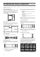
The “CS1D Operating Manual (Start-up)” is an introductory manual that explains how to connect the various compo-
nents of the PM1D system and verify that the PM1D system is operating correctly.
When starting up the PM1D system for the first time, or if you have changed the configuration of the system such as
when the PM1D system has been moved to another location and/or re-connected, we recommend that you follow the
procedure described in this manual to verify that the system is operating correctly.
•
This manual explains only the minimum operations.
For details on operating the PM1D system, please
refer to “CS1D Operating Manual (Basic operation)”
•
For details on the specifications and functionality of
the engine (DSP unit DSP1D-EX {DSP1D}) and I/O
units, please refer to the owner’s manual included
with each device.
•
For details on the function and operation of the con-
trollers and connectors found on the top panel, rear
panel, and front panel of the console (CS1D), refer to
“CS1D Reference Manual (Hardware).”
•
For details on the software in the display screen of
the console (CS1D), refer to “CS1D Reference Man-
ual (Software).”
Screen shots shown in this manual are taken from a
prototype. Please be aware that they may differ
slightly from the actual screens on your unit.
Printing conventions in “CS1D Operating Manual (Start-up)”
•
Differences between the 96 channel model and 48
channel model
In general, the “CS1D Operating Manual (Start-up)”
is written with the 96 channel model PM1D system
(the model with the DSP1D-EX as the engine) in
mind. Where the functionality of the 96 channel
model differs from the 48 channel model (the model
with the DSP1D as the engine), the functionality of
the 48 channel model is enclosed in curly brackets { }.
•
Standard mode and Mirror mode
The PM1D system has two operation modes (ele-
ments that determine system structure and connec-
tion method); “Standard mode” in which one
console is connected to one engine, and “Mirror”
mode in which one console is connected to two
engines of which only one is used.
Be aware that the mode used by the PM1D system
will depend not only on the number of engines, but
also on the type of connections and on the internal
settings.
Explanations that apply only to
Standard mode
will
be indicated by the following symbol.
Explanations that apply only to
Mirror mode
will be
indicated by the following symbol.
The PM1D system version 1.0 does not support any
other operation mode (i.e., other than Mirror
mode) in which two engines are used.
•
Distinguishing between the controls of the CS1D
and the on-screen knobs/buttons
Names of controls (switches, encoders, faders) on the
top panel, rear panel, and front panel of the CS1D
are enclosed in square brackets [ ] in order to distin-
guish them from the knobs and buttons etc. that are
displayed in the screen.
Example
: Tu rn on the [TO ST] switch.
(This indicates an operation on the top panel of the
CS1D.)
Example
: Click the BASIC button.
(This indicates an operation in the display screen.)
•
Va r ious icons
The following icon is used to call your attention to
various tips for operation or to reference pages.
The following icon is used to indicate particularly
important items or operations that you must be
aware of.
DSP
x1x1
DSP
x2x2
Hint