
User Manual
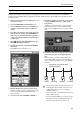
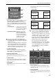


Table Of Contents
- Additions/changes in V1.5
- Changes to the constantly-displayed screen
- DUAL CONSOLE mode added
- Cascade connections
- Using GPI (General Purpose Interface)
- Fader Start function
- Tap Tempo function
- Added functions in the USER DEFINE screen
- Input channel panel assignments
- Horizontal pair and vertical pair
- Mix minus
- Job select
- Auto Store function
- Global Paste function
- Parameter control via CONTROL CHANGE and NRPN
- Manual Fading function
- Unit name
- Matrix send shortcuts
- DCA mute indicator
- Oscillator improvements
- Improvements in the INPUT PATCH / OUTPUT PATCH screens
- USB PC (computer) connection
- Automatic scrolling in the CH to MIX screen and MATRIX/ST ROUTING screen
- ON/OFF button for COMM IN
- Added functions in the PREFERENCE screen
- Supplementary explanation for existing functions
- Scene Memory/Effect Library to Program Change Table
- MIDI control change NRPN (Non Registered Parameter Number) assignment table
- MIDI control change parameter assignment table
- MIDI Data Format
Input channel panel assignments
53
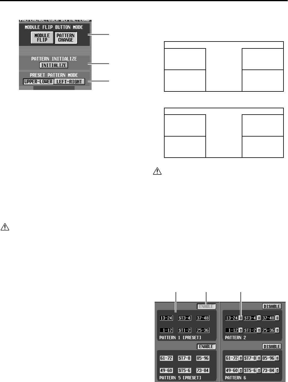
1 MODULE FLIP BUTTON mode
These buttons choose one of the following two func-
tions for the MODULE [FLIP] switch in the
SELECTED INPUT CHANNEL section. (This also
applies to a USER DEFINE switch or GPI IN trigger
to which the RIGHT SIDE PANEL FLIP function is
assigned.)
• MODULE FLIP ..........As in previous versions, the
input channels assigned to
the upper and lower INPUT
blocks will be changed.
• PAT TERN CHANGE .Each time you press the
MODULE [FLIP] switch,
the panel assignment pat-
terns registered in the pat-
tern list (7) of the PANEL
ASSIGN screen will be
selected successively.
If you turn off the MODULE FLIP/PATTERN
CHANGE LINK button (A), the MODULE [FLIP]
switch will be valid only for the left side of the panel
(INPUT block 1/2).
In this case, module flip switching for the right side
(ST IN block 1/2, INPUT block 3/4) is performed
by the USER DEFINE switches, the MODULE but-
tons located in the lower part of the screen, or the
GPI function RIGHT SIDE PANEL FLIP (→p.37).
2 PAT TERN INITIALIZE
When you click this button, the PANEL ASSIGN
screen settings (with the exception of PRESET PAT-
TERN MODE (3)) will be initialized.
3 PRESET PATTERN MODE
These buttons select one of the following two
arrangements for the preset patterns (patterns 1 and
5).
• UPPER-LOWER
This is the existing default arrangement, in which
input channels are arranged in the order of INPUT
block 1→2→3→4.
• LEFT-RIGHT
Input channels are arranged in the order of INPUT
block 1→3→2→4.
Preset pattern 1 will be as follows when each arrange-
ment is selected.
• Even if you use the PATTERN INITIALIZE but-
ton (2) to execute initialization, the PRESET
PATTERN MODE setting will not be affected.
When you execute initialization, the arrangement
of pattern 1 will be copied to patterns 2–4, and
the arrangement of pattern 5 will be copied to
patterns 6–8. This means that the PRESET PAT-
TERN MODE settings (UPPER-LOWER/LEFT-
RIGHT) will be applied to all patterns 1–8.
• The arrangement of the SCENE function
TRACKING RECALL screen (when the MODE
button has selected INPUT 1–48 or INPUT 49–
96) and the METER function input channel
screens will change according to the PRESET
PATTERN MODE.
4 Pattern display area
This area shows the channel configurations of the
preset patterns (patterns 1 and 5) and user patterns
(patterns 2–4, 6–8).
5 ENABLE/DISABLE
Enables/disables each pattern. Patterns for which this
button is set to ENABLE will be registered in the pat-
tern list (7).
1
2
3
UPPER-LOWER
INPUT block 2
CH13-24
INPUT block 1
CH1-12
INPUT block 4
CH37-48
INPUT block 3
CH25-36
LEFT-RIGHT
INPUT block 3
CH25-36
INPUT block 1
CH1-12
INPUT block 4
CH37-48
INPUT block 2
CH13-24
4 5 6