DIGITAL IO BOX Owner’s Manual V516420 R2 1 IP 20 100 CR Printed in Japan E
FCC INFORMATION (U.S.A.) 1. IMPORTANT NOTICE: DO NOT MODIFY THIS UNIT! This product, when installed as indicated in the instructions contained in this manual, meets FCC requirements. Modifications not expressly approved by Yamaha may void your authority, granted by the FCC, to use the product. 2. IMPORTANT: When connecting this product to accessories and/or another product use only high quality shielded cables. Cable/s supplied with this product MUST be used. Follow all installation instructions.
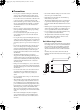
Dio8_E_Body Page 3 Wednesday, February 28, 2007 10:21 AM ■ Precautions • The digital circuits of this unit may induce a slight noise into nearby radios and TVs. If noise occurs, relocate the affected equipment. Rack Mounting Caution If the unit is rack mounted and transported regularly, for example, when on a tour, we recommend that the rear of the unit be supported by fitting a pair metal brackets, one each side. The following drawing provides the information necessary to make such brackets.
Thank you for choosing the DIO8 digital IO box, specifically designed for the Yamaha PM1D digital audio mixing system. The DIO8 outputs and inputs digital signals (such as ADAT, TASCAM, and AES/EBU) as well as analog signals to and from the DSP1D/DSP1D-EX engine controlled via the CS1D control surface. Up to eight digital I/O cards and analog I/O cards can be installed on each DIO8.
E1: The OUTPUT connector of the DIO8 is connected to the OUTPUT connector of the DSP unit. Please connect it to the INPUT connector. E2: The INPUT connector of the DIO8 is connected to the INPUT connector of the DSP unit. Please connect it to the OUTPUT connector. (This will not be displayed if the OUTPUT connector of the DIO8 is connected.) E3: Either the cable connected to the INPUT or OUTPUT connector has become disconnected, or the connection destination is incorrect.
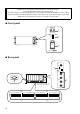
● Using slots 1-4 input signals with two DSP1D/ DSP1D-EXs simultaneously 1) Connect the INPUT A connector of the DIO8 to OUTPUT slot 1-6 of the first DSP1D/DSP1D-EX. 2) Connect the INPUT B connector of the DIO8 to the second DSP1D/DSP1D-EX OUTPUT slot connector with the same ID number as the first unit’s slot you connected in Step 1). 3) Connect the OUTPUT A connector of the DIO8 to the INPUT connector for INPUT slot 1-10 of the first DSP1D/DSP1D-EX.
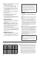
[AP8AD]+[AP8DA] cards used [MY8-AD]+[MY4-AD]+ [MY4-DA] cards used Total 0 cards [MY8-TD]+[MY8-AT]+[MY8-AE] cards used Up to a total of 8 cards Total 1 card Up to 6 cards Up to the number of vacant DIO8 slots Total 2 cards Up to 4 cards Up to the number of vacant DIO8 slots Total 3 cards Up to 2 cards Up to the number of vacant DIO8 slots Total 4 card Up to 1 card Up to the number of vacant DIO8 slots Total 5 or more cards cannot be used — — Installing an optional I/O card Important! Befor
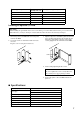
I/Os I/O connectors Level Type INPUT A, B RS422 D-sub, half-pitch, 68-pin connector (female) OUTPUT A, B RS422 D-sub, half-pitch, 68-pin connector (female) COM RS232C D-sub,9-pin connector (male) WORD CLOCK IN TTL/75 Ω (ON/OFF) *1 BNC connector WORD CLOCK OUT (X4) TTL/75 Ω BNC connector *1 On the rear panel Slots Eight slots (slots 1-8) are available on the DIO8 for installing digital I/O cards and analog I/O cards. Slot 1 supports a serial interface card (not released yet).
YAMAHA CORPORATION Pro Audio & Digital Musical Instrument Division P.O.