PM5D Editor Owner’s Owner’s Manual Manual Special Notices Contents • The software and this owner’s manual are the exclusive copyrights of Yamaha Corporation. • Copying of the software or reproduction of this manual in whole or in part by any means is expressly forbidden without the written consent of the manufacturer. • Copying of the commercially available music sequence data and/or digital audio files is strictly prohibited except for your personal use.
Getting Started Overview of PM5D Editor PM5D Editor enables you to remotely control the Yamaha PM5D mixing console and to save the parameter settings on your computer. To use PM5D Editor, you must first perform the following operations: 1 Start and configure Studio Manager. 2 Start and configure PM5D Editor. 3 Synchronize PM5D Editor with your PM5D console ( ➥ p.3). NOTE For more information on using Studio Manager, refer to the Studio Manager Owner’s Manual.
❏ Console Setup To open the Mixer Setup window, choose [Mixer Setup] from the [File] menu. Pair Mode: Select whether faders will be paired Horizontally or Vertically. Pan Nominal Position: Select whether the signal will be at nominal level when panned to the center (Center) or when panned all the way to left or right (L<->R). You can make separate settings for monaural channels and paired channels. Bus Setup: Select the MIX bus mode (VARI/FIXED) for every two adjacent odd-numbered/even-numbered MIX buses.
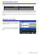
Working with Sessions All of your console’s mix settings in PM5D Editor, including Scene and library data, are called Sessions. The following table describes how to handle Sessions. Creating a new Session Opening a previously saved Session Saving the current Session Saving the current Session with a new name Choose [New Session] from the [File] menu. Choose [Open Session] from the [File] menu. Choose [Save Session] from the [File] menu. Choose [Save Session As...] from the [File] menu.
Undo/Redo Function In PM5D Editor, you can cancel the latest operation (Undo) and also cancel the cancellation of the latest operation (Redo). If you perform an Undo operation twice in a row, you can cancel the two most-recent operations. If you perform an Undo operation three times in a row, you can cancel the three most-recent operations. In this way, you can cancel multiple recent operations. The following table describes how to use the Undo/Redo function. Undo Redo Choose [Undo] from the [Edit] menu.
INPUT CH window This window displays the mix parameters of input channels 1–24 or 25–48. The window shows either the channel 1– 24 layer or the channel 25–48 layer. To open the other layer’s window, choose the [Windows] menu command [INPUT CH] and choose “CH1-24” or “CH25-48.” You can use the [View] menu to choose the parameters that will be displayed in the window. 1 2 3 A Input patch Here you can select an input source to assign to the input channel, from the following choices.
4 5 6 7 8 9 J D HPF (High Pass Filter) Switches the high pass filter on/off. You can drag the numeric value up or down to edit the cutoff frequency. E Ø (Phase) Inverts the phase of the signal after AD conversion. F INSERT Enables/disables the insert-out that is patched in the PM5D’s INSERT PATCH screen (INPUT PATCH function). G DIRECT Enables/disables the direct output that is patched in the PM5D’s DIRECT OUT PATCH screen (INPUT PATCH function). K L H GATE Turns the gate on/off.
Q R Q Channel name This is a text box that displays the channel name. You can also edit the channel name in this text box. Note that while the channel number (L) will not change even if you switch the pair mode, the channel name display will change according to the pair mode. For example if the CH1-24 layer is displayed, switching from Horizontal Pair mode to Vertical Pair mode will change the channel name display from channels 1, 2, 3 ... 24, 25 to channels 1, 3, 5...45, 47.
ST IN window In this window you can view and edit the mix parameters of ST IN channels 1–4. You can use the [View] menu to choose the parameters that will be displayed in the window. 1 2 A Input patch Selects the input source that will be assigned to the ST IN channel. The input sources that can be assigned are the same as for an input channel (➥ p.6).
8 9 J H GATE Turns the gate on/off. The indicator immediately below the button shows the gate’s on/ off setting and the open/closed status (➥ p.7). I COMP (Compressor) Switches the compressor on/off. When the compressor is on, the GR meter immediately below the button shows the amount of gain reduction. K L J EQ (Equalizer) Switches the EQ on/off (the L/R settings are linked). The graph immediately below the button shows the approximate response of the EQ.
FX RTN window In this window you can view and edit the mix parameters of FX RTN channels 1–4. You can use the [View] menu to choose the parameters that will be displayed in the window. 1 2 A Input patch Selects the input source that will be assigned to the FX RTN channel. The input sources that can be assigned are the same as for an input channel (➥ p.6).
7 G Channel number This is the number of the FX RTN channel for this module. You can double-click this number to open the Selected Channel window for this channel. H MIX SEND 8 The send levels of the signals sent from the FX RTN channel to the VARI-type MIX buses are shown as bar graphs (the L/R settings are linked). You can also adjust the send levels by dragging a bar graph to left or right.
MIX window In this window you can view and edit the parameters of MIX channels 1–24. You can use the [View] menu to choose the parameters that will be displayed in the window. 1 2 3 4 5 A EQ (Equalizer) Switches the EQ on/off. The graph immediately below the button shows the approximate response of the EQ. You can drag the graph to edit the response of the EQ, or hold down the key ( key) of your computer keyboard and click the graph to reset it to a flat response.
F MTRX (Send level to MATRIX buses) 6 7 8 9 J K These bar graphs indicate the send levels of the signals sent from the MIX channel to each MATRIX bus. You can also adjust the send levels by dragging a bar graph to left or right. The bar graph display will change as follows according to the send position (pre/post) and on/off status of the signal sent from the MIX channel to the MATRIX buses.
MATRIX window In this window you can view and edit the parameters of MATRIX channels 1–8. You can use the [View] menu to choose the parameters that will be displayed in the window.
A MIX (Send levels from the MIX channels to the MATRIX bus) Here you can view and edit the send levels of the signals sent from each MIX channel to the MATRIX bus. The method of operation and the meaning of the display are the same as for (6) MTRX in the MIX window (➥ p.14). B STEREO (Send levels from the STEREO channels to the MATRIX bus) 1 Here you can view and edit the send levels of the signals sent from the STEREO A/B channels to the MATRIX bus.
STEREO window In this window you can view and edit the parameters of the STEREO A/B channels. You can use the [View] menu to choose the parameters that will be displayed in the window.
1 2 3 4 5 A EQ (Equalizer) Switches the EQ on/off (the L/R settings are linked). The graph immediately below the button shows the approximate response of the EQ. You can drag the graph to edit the response of the EQ, or hold down the key ( key) of your computer keyboard and click the graph to reset it to a flat response. B COMP (Compressor) Switches the compressor on/off (the L/R settings are linked).
DCA window In this window you can view and edit the parameters of DCA groups 1–8. 1 2 3 A DCA number This is the number of the DCA group. B MUTE This switches DCA group muting on/off. This is linked with the DCA [MUTE] keys in the DCA strip section of the PM5D panel. C DCA group name 4 This is a text box that displays the DCA group name. You can also edit the DCA group name in this text box. D DCA fader 5 This fader adjusts the level of the DCA group.
Selected Channel window Here you can set the parameters of the currently selected input channel (input channels 1–48, ST IN channels 1–4, FX RTN channels 1–4) or output channel (MIX channels 1–24, MATRIX channels 1–8, STEREO A/B channels). The type of parameters that can be edited in this window will depend on the type of the currently selected channel.
❏ HA GAIN/Ø/HPF (HA gain/phase/high-pass filter) 1 2 3 A HA GAIN Adjusts the gain of the internal head amp (PM5D-RH model only) or of the external head amp (AD8HR, AD824) patched to the input channel. The current setting is shown in the numerical box above the knob. You can also use the +48V button to switch phantom power on/off. B Ø (Phase) Inverts the phase of the signal after AD conversion. C HPF (High Pass Filter) Use the HPF button at the right to switch the high-pass filter on/off.
F DECAY (Decay time) Specifies the time over which the gate will close after the hold time has elapsed. G ATTACK (Attack time) Specifies the time from when the key-in signal exceeds the threshold level until the gate opens. H HOLD (Hold time) Specifies the time that the gate will remain open after the key-in signal falls below the threshold. I ON (On/off) This button switches the gate on/off. J LIBRARY This button accesses the gate library.
❏ COMPRESSOR 1 2 4 3 6 5 9 K J 8 7 M L N A Compressor graph Indicates the approximate response for the compressor of the currently selected channel. B GR meter This meter indicates the amount of gain reduction produced by the compressor. C TYPE Indicates the type of the currently selected compressor. D THRESHOLD (Threshold level) Specifies the threshold level at which the compressor will operate.
❏ INSERT (except for FX RTN channels) 1 2 3 4 A ON (On/off) Enables/disables insert-in/out. B OUT (Insert out) Here you can select the output port that will be assigned to insert-out, from the following choices. NONE SLOT1-1, SLOT1-2...SLOT4-15, SLOT4-16 FXIN1L, FXIN1R...FXIN8R, FXIN8L GEQIN 1–12 2TR D1L, 2TR D1R...
❏ EQUALIZER 2 1 8 7 6 3 4 5 J 9 K M L A EQ graph Indicates the approximate response for the EQ of the currently selected channel. B FLAT If you click this button, the gain of all bands will be reset to 0.0 dB. CQ D F (Frequency) E GAIN These knobs adjust the Q, center frequency, and boost/cut amount for the four bands LOW, LO-MID, HI-MID, and HIGH. F (LOW shelving) If this button is on, the LOW EQ will be switched to a shelving type (the Q knob of the LOW EQ will disappear).
M ATT (Attenuation) Adjusts the amount of attenuation/gain following AD conversion. ❏ DELAY A TIME (Delay time) Adjusts the delay time for each channel. B ON (On/off) Switches the delay on/off. The current value (ms units) is shown in the box at the right. 1 2 ❏ M/S DECODE (except for FX RTN channels) A S-GAIN This knob sets the proportionate level of the S mic relative to the level of the M mic. The current value (dB units) is shown in the box at the right.
❏ Pan / Fader 1 2 3 4 5 6 7 A DIRECT (except for FX RTN channels) Turns the direct output on/off. B Direct Output Port (except for FX RTN channels) Choose the port from which this input channel 1–48 or this ST IN channel 1–4 will be directly output. NONE SLOT1-1, SLOT1-2...SLOT4-16 2TR D1L, 2TR D1R...
❏ CH to MIX (Channel to mix) 2 1 3 4 5 A MIX send level This adjusts the send level of the signal sent from the input channel to VARI-type MIX buses. The current value is shown in the numerical box immediately above. B Pair This indicates the pairing status of adjacent odd-numbered/even-numbered MIX channels. You can click the heart symbol to enable/disable pairing. C ON (MIX send on/off) This is an on/off switch for the signal sent from the input channel to the MIX bus.
If a MIX channel is selected ❏ CHANNEL SELECT (Channel selection) Except for the fact that your editing applies to a MIX channel, this is the same as for an input channel (➥ p.20). ❏ COMPRESSOR Except for the fact that the COMP LINK GROUP is A–F, and that the types of signal that can be selected for keyin are different, this is the same as for the compressor of an input channel (➥ p.23).
❏ EQUALIZER 2 1 9 8 7 6 3 4 5 K J L M N A EQ graph Indicates the approximate response for the EQ of the currently selected channel. B FLAT If you click this button, the gain of all bands will be reset to 0.00 dB. CQ D F (Frequency) E GAIN These knobs adjust the Q, center frequency, and boost/cut amount for each band. F (LOW shelving) If this button is on, the LOW EQ will be switched to a shelving type (the Q knob of the LOW EQ will disappear).
L TYPE I/TYPE II (EQ type) Selects either TYPE I (an algorithm equivalent to the EQ in the earlier 02R series) or TYPE II (a newly developed algorithm) as the EQ type. M EQ LINK GROUP Selects the EQ link group (A–F) to which that channel belongs. N UPPER/LOWER Switches the four bands affected by controls 3–9 between LOWER (1 LOW–4 HIGH) and UPPER (5 LOW–8 HIGH). ❏ DELAY This is the same as for the delay settings of an input channel (➥ p.26).
❏ Pan / Fader A TO ST (To stereo) 1 This is an on/off switch for the signal sent from the MIX channel to the STEREO bus. The PRE button located below selects PRE (immediately before the MIX [ON] key) or POST (immediately after the MIX [ON] key) as the point from which the signal is sent from the MIX channel to the STEREO bus. B TO ST PAN (To stereo pan) Sets the panning of the signal sent from the MIX channel to the STEREO bus. 2 3 4 C LCR Turns LCR mode on/off for each channel.
❏ MIX to MATRIX 2 1 3 4 5 A MATRIX send level This adjusts the send level of the signal sent from the MIX channel to the MATRIX buses. B Pair This indicates the pairing status of adjacent odd-numbered/even-numbered MATRIX channels. You can click the heart symbol to enable/disable pairing. C ON (MATRIX send on/off) This is an on/off switch for the signal sent from the MIX channel to the MATRIX bus.
If a MATRIX channel is selected ❏ CHANNEL SELECT (Channel selection) Except for the fact that your editing applies to a MATRIX channel, this is the same as for an input channel (➥ p.20). ❏ COMPRESSOR Except for the fact that the COMP LINK GROUP is A–F, and that the types of signal that can be selected for keyin are different, this is the same as for the compressor of an input channel (➥ p.23).
❏ Pan / Fader A BALANCE 1 2 This adjusts the left/right output balance of paired channels. This is not shown if pairing is not specified. B ON This switches the MATRIX channel on/off. This is linked with the MATRIX [ON] keys in the MATRIX section of the PM5D panel. C Fader 3 This adjusts the output level of the MATRIX channel. This is linked with the MATRIX encoders in the MATRIX section of the PM5D panel. The current value is shown in the numerical box immediately below.
❏ COMPRESSOR Except for the fact that the COMP LINK GROUP is A–F, and that the types of signal that can be selected for keyin are different, this is the same as for the compressor of an input channel (➥ p.23). ❏ INSERT Except for the fact that the insert points that can be selected are different, this is the same as for the insert settings of an input channel (➥ p.24). ❏ EQUALIZER This is the same as the equalizer settings of a MIX channel (➥ p.30).
❏ STEREO to MATRIX 2 1 3 4 A MATRIX send level Here you can adjust the send levels of the signals sent from the STEREO A/B channels to the MATRIX bus. B Pair This indicates the pairing status of adjacent odd-numbered/even-numbered MATRIX channels. You can click the heart symbol to enable/disable pairing. C ON (MATRIX send on/off) This is an on/off switch for the signal sent from the STEREO A/B channel to the MATRIX bus.
Patch Editor window Here you can assign the input/output port for each channel, its direct output, and its insert-in/out. This window is divided into INPUT PATCH, OUTPUT PATCH, INPUT INSERT PATCH, OUTPUT INSERT PATCH, DIRECT OUT PATCH, and PATCH LIST pages. To switch pages, click the tabs shown in the upper part of the window. INPUT PATCH page Here you can select the input port that is assigned to the input of each input channel.
INPUT INSERT PATCH page Here you can assign input/output ports to the insert-in/out of each input channel. Select the output port in the left side of the screen, and the input port in the right side of the screen. Except for the fact that you can resize the window, the basic operation is the same as in the PM5D’s INPUT INSERT PATCH screen. OUTPUT INSERT PATCH page Here you can assign input/output ports to the insert-in/out of each output channel.
DIRECT OUTPUT PATCH page Here you can select the output port that will directly output each input channel. Except for the fact that you can resize the window, the basic operation is the same as in the PM5D’s DIRECT OUTPUT PATCH screen. PATCH LIST page Here you can view and edit the input patch and output patch settings. Input patch, output patch, and channel name data that was written to a CSV file by the PM5D itself can also be loaded into this page.
6 1 2 7 3 4 5 A Input channel number B Input channel name This is the number and name of the input channel. You can click the channel name box to edit the name in this page. C Input port This shows the input port assigned to the input channel. You can click this box and choose the input port from the popup menu that appears. D Output channel number This is the number of the output channel. E Output port This shows the output port assigned to the output channel.
Surround Editor window Here you can make surround panning settings for the two currently selected input channels. 1 2 3 4 5 A SELECT (Channel selection) This area displays the name and number of the two channels selected for operations (two adjacent odd-numbered/even-numbered input channels, a ST IN channel, or an FX RTN channel). To switch channels, use the SELECT button or the / buttons at left and right. You can also edit the channel name in the text box.
9 J 8 6 7 K F DIVERGENCE These controls specify the proportion at which the signals are sent to each surround bus when the input channel is positioned in the center. The operable parameters will change as follows, according to the surround mode that is currently selected. • Surround mode= 3-1ch/5.1ch The F knob will be operable, allowing you to adjust the front divergence.
GEQ window In this window you can select the insertion destination of GEQ modules 1–12, and edit the parameters. 1 2 3 4 5 A MODULE (Module selection) Selects the GEQ module that you want to edit or view. B INSERT (Insert destination) Select one of the following as the insert destination for the currently selected GEQ module. NONE INS CH1...INS CH48 INS STIN1L, INS STIN1R...INS STIN4R INS MIX1...INS MIX24 INS MTX1...
6 8 7 9 F GEQ graph This graph shows the response of the currently selected GEQ module. G GEQ faders These faders cut/boost the frequency bands of the GEQ module. The value of each fader is shown in the numerical box below it. H LIMIT The range and direction of adjustment controlled by the faders can be selected from the following: ±15 dB, ±12 dB, ±6 dB (these are valid in both the boost and cut directions), or –24 dB (valid only in the cut direction).
Effect Editor window Here you can select the effect type for internal effects 1–8, edit the parameters, and specify the input/output patching. NOTE You can also open multiple Effect Editor windows to simultaneously view the settings of different-numbered internal effects. However, the PM5D itself will be linked only with parameter edits performed in the window you opened first. (Parameter edits performed in the PM5D’s own screen will be valid.) 1 2 3 4 A EFFECT No.
E Effect parameters This area shows the effect parameters and knobs for the currently selected effect type. 5 6 7 8 9 F Input meter Indicates the level of the signal being input to the internal effect. G Input patch Click the L CHANNEL or R CHANNEL area, and choose one of the following as the signal route that will be patched to the L/R input channels of the internal effect. –– MIX 1...MIX24 INSCH1...INSCH48 INSSTIN1L, INSSTIN1R...INSSTIN4R INSMIX1...INSMIX24 INSMTX1...
H Output meter Indicates the level of the signal being output from the internal effect. I Output patch Click the L CHANNEL or R CHANNEL area, and choose one of the following as the signal route that will be patched to the L/R output channels of the internal effect. –– CH 1...CH48 STIN1L, STIN1R...STIN4R FXRTN1L, FXRTN1R...FXRTN4R INSCH1...INSCH48 INSSTIN1L, INSSTIN1R...INSSTIN4R INSMIX1...INSMIX24 INSMTX1...
L N M O P L MIX BALANCE Adjusts the balance of the effect sound relative to the original sound. 0 (%) outputs only the original sound, and 100 (%) outputs only the effect sound. M BYPASS This button temporarily bypasses the effect. N CUE This button cue-monitors the output of the currently selected effect. O TEMPO If a tempo-type or modulation-type effect is selected, this allows you to adjust time-related parameters such as DELAY (delay time) and FREQ. (modulation speed).
DCA/Mute Group window In this window you can select the channels that will be assigned to each DCA group and mute group. This window is divided into two pages; the DCA GROUP ASSIGN page and the MUTE GROUP ASSIGN page. DCA GROUP ASSIGN page Here you can specify the channels that will be assigned to DCA groups 1–8. The upper part of the screen lets you assign input channels to DCA groups, and the lower part of the screen lets you assign output channels to DCA groups.
C Grid This grid lets you assign channels (horizontal rows) to DCA groups (vertical columns). Currently-patched grids are indicated by a symbol. To enable or disable an assignment, click the desired grid. D CLEAR These buttons clear all input channels and output channels assigned to the corresponding DCA group. When you click one of these buttons a window will appear, asking you to confirm the operation. To execute the Clear operation, click the OK button.
1 2 3 5 4 A Mute group This area shows the mute group number. B MUTE MASTER (Mute master) These buttons enable/disable each input channel or output channel mute group. C Grid This grid lets you assign channels (horizontal rows) to mute groups (vertical columns). Currently-patched grids are indicated by a symbol. To enable or disable an assignment, click the desired grid. D MUTE SAFE ON (Mute Safe on/off) These buttons switch Mute Safe on/off for each channel.
Scene window Here you can manage scene memories, and make various settings related to scene recall operations. This window is divided into SCENE MEMORY, EVENT LIST, RECALL SAFE, and FADE TIME pages. To switch pages, click the tabs shown in the upper part of the window. SCENE MEMORY page Here you can edit the PM5D’s scene memories. You can also load scene library files from a memory card or from a drive of your computer, and edit them.
F FILE This area lists the scenes in the file you opened using the OPEN button ( 1). The list includes the following items. HINT To view items that are not currently shown, scroll the list to the right. The boundary lines in the center of the window can be dragged toward the right to expand the file list display area as shown below. 7 8 9 J K G No. (Scene number) This is the scene number 000–500. H TITLE This is the scene title. You can also double-click this area and edit the title.
O P Q O TX (MIDI event transmission) If you click this column to make the “TX” indication appear, transmission will be enabled for the MIDI event specified for this scene. P GPI OUT CONTROL Specifies the polarity (high-active/low-active) and transmission method (tally/trigger) of the signal that is sent from GPI OUT ports 1–12 when the scene is recalled. You can also click these columns to edit the setting. You can choose from the following settings.
• To select a single scene Click the line containing the desired scene. • To select multiple consecutive scenes Click the first scene to select it; then hold down the key and click the last scene. • To select multiple non-consecutive scenes Click the first scene; then hold down the key ( key) and click each of the remaining scenes.
EVENT LIST page In this page you can see how the scenes registered in the PM5D’s EVENT LIST screen will be switched according to the progression of time code or according to the elapsed time since the most recent Recall operation. NOTE • This page functions as a viewer of the PM5D’s EVENT LIST screen. You cannot register or recall events from within this page.
RECALL SAFE page Here you can make settings for the Recall Safe function that excludes only specific channels from recall operations of all scenes. Except for the fact that there is no PASTE button for copying and pasting parameter settings from the SELECTIVE RECALL screen, the display and operations within this page are the same as in the PM5D’s RECALL SAFE screen.
1 2 A FADING ENABLE (Fade function enable/disable) Switches the Fade function for fader levels between enabled and disabled. B INPUT CHANNEL PANNING ENABLE (Input channel panning enable/disable) Switches the Fade function for input channel pan (balance) parameters between enabled and disabled. If this button is on, you can use the two buttons located at the right to select the input channels to which this setting will apply.
Library window Here you can edit the PM5D’s various libraries. You can also load library files that were saved on a drive of your computer, edit the order or title of library items, recall the desired library data, or copy desired library data to a library within the PM5D. This window is divided into INPUT CH, OUTPUT CH, GATE, COMP, INPUT EQ, OUTPUT EQ, INPUT PATCH, OUTPUT PATCH, EFFECT, GEQ, and HA pages; to switch pages, click the tabs located at the top of the window.
7 8 9 K L J M N G No. (Number) This column indicates the number of each item in the library. H TITLE This column indicates the title assigned to each library item. You can also double-click this area and edit the title. I PROTECT This indicates the Protect setting on/off. This area displays a lock icon for protected data; this data cannot be overwritten, nor its title edited. Read-only data is indicated by “READ” displayed in this column. J INTERNAL DATA This area shows the PM5D’s library contents.
Meter window Here you can view the signal levels within the PM5D, or the amount of gain reduction produced by the internal compressors and gates. This lets you check signal presence, overload status, and compressor/gate operation from your computer. This window is divided into INPUT METER, OUTPUT METER, INPUT GR, and OUTPUT GR pages. To switch pages, click the tabs shown in the upper part of the window.
Keyboard Shortcuts Menu File menu Edit menu Windows menu Library window or SCENE MEMORY page of the Scene window Action Windows Macintosh Creates a new Session Ctrl+N +N Opens a previously saved Session Ctrl+O +O Saves the current Session Ctrl+S +S Undo Ctrl+Z +Z Redo Ctrl+Y +Y Closes the active window Ctrl+W +W Closes all windows Ctrl+Alt+W +Option+W Opens the Sync window Ctrl+1 +1 Opens the INPUT CH (CH1-24) window Ctrl+2 +2 Opens the INPUT CH (CH25-48) window Ctrl+Alt+
Index A ALL INPUT CHANNEL ................ 59 B Bus Setup .......................................... 3 BYPASS .......................................... 49 C CH to MIX ..................................... 28 Channel to mix .............................. 28 CLEAR ...................................... 56, 61 CLEAR ALL .................................... 59 CLOSE ...................................... 53, 60 COMMENT ................................... 54 CSV file Export ...................................
Pan / Fader ............. 27, 32, 35, 36 STEREO A/B channel .............. 35 STEREO to MATRIX ............... 37 Selective recall ................................ 54 Sessions ............................................ 4 SET ALL ......................................... 59 Setup Console ....................................... 3 System ........................................ 2 ST IN window .................................. 9 Stereo B ............................................ 3 STEREO to MATRIX .......