
User Manual

PM5DV2/DSP5D Editor Owner’s Manual
4
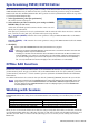
Number of Effects:
This changes the number of assigned internal effects and GEQ modules. Decreasing the
number of internal effects by one will increase the number of available GEQ modules by one. You can change the
number assigned between eight internal effects (and twelve GEQ modules) to no internal effects (and twenty
GEQ modules). You can use up to eight GEQ modules as effects.
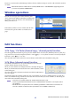
+48V Master:
This function is found only in DSP5D Editor. It is the master switch for the phantom power
(+48V) supplied to INPUT jacks 1–48 and ST IN jacks 1–4. If this switch is off, phantom power will not be
applied, regardless of whether the +48V shown in the display is on or off.
Surround Mode:
Select the surround mode (STEREO, 3-1, 5.1, 6.1).
External HA:
This specifies the connection ports for external HA (AD8HR) units connected via the slots.
External HA units are assigned an ID of 1–8 (1–4 on the DSP5D), and here you can select the ports to which each
will be connected.
IP Address:
This function is found only in DSP5D Editor. You can specify the IP Address, Subnet Mask, and
Default Gateway values. If the DSP5D and computer are connected in a one-to-one correspondence, we recom-
mend that you use the following default values.
•
IP Address
................... 192.168.0.129
•
Subnet Mask
............... 255.255.255.0
•
Default Gateway
......... 192.168.0.1
•For details on network settings for your computer, refer to DME-N Network Driver installation guide for
DSP5D(Windows) or Network-MIDI Driver installation guide(Mac).
• If you changed the IP Address, you must close DSP5D Editor and Studio Manager, and re-specify the
IP Address values for the DME-N Network Driver communication port or the Network-MIDI Driver com-
munication port. The connection between the DSP5D and DSP5D Editor will be broken when you
change the IP Address
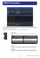
Cascade Connection:
This function is found only in DSP5D Editor. It specifies the Cascade Machine ID
when using a cascade connection. If this is set to 1, you will be able to make DME Connection settings. If this is
set to 2 or 3, the Cascade setting will be Slave, and you won’t be able to make DME Connection settings.
DME Connection:
This function is found only in DSP5D Editor. This is a setting for connecting the DSP5D
with a DME series unit (except the DME32). For details on the connection method, refer to the Global function
MIDI Remote Function section in the reference section of the DSP5D manual.
Even if you enable DME Connection, remote control of the DME cannot be performed from DSP5D Editor.
Use the separate DME Designer to remotely control the DME.
• Input Port / Output Port
This specifies the DSP5D’s connector/slot to which the DME is connected. You can choose SLOT1, SLOT2,
CASCADE IN/OUT D-SUB, or CASCADE OUT RJ-45.
• If you select CASCADE IN/OUT D-SUB or CASCADE OUT RJ-45, the Slot display area of Patch Editor
will show the selected connector/slot.
• Since CASCADE IN RJ-45 cannot be used, you must connect the DSP5D via its CASCADE OUT RJ-
45 connector if you use an Ethernet cable to connect the DME and DSP5D.
• Monitor Port
This specifies the DSP5D port that will receive monitor signals from the DME. You can select stereo channels
from within the port selected by Input Port.
• Connect
This initiates or ends communication between the DSP5D and DME. Communication will begin if this check
box is selected, and will end if this check box is cleared. The actual start or end of communication will occur
when you click the OK button.
• MIDI Program Change
This allows the DME to recall a scene according to the Program Change Table assignment in synchronization
with scene recall that occurs on the DSP5D. If you enable this function by selecting the check box, synchroni-
zation via MIDI program change will be enabled. In order to enable this function, the Connect check box
must be selected.
NOTE
NOTE
NOTE