
User Manual

PM5DV2/DSP5D Editor Owner’s Manual
8
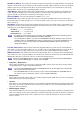
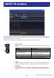
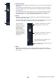
This window displays the parameters of input channels 1–24 or 25–48. The window shows either the channel 1–24
layer or the channel 25–48 layer. To open the other layer’s window, choose the [Windows] menu command [INPUT
CH] and choose “CH1-24” or “CH25-48.”
You can use the [View] menu to choose the parameters that will be displayed in the window.
A Input patch
Here you can select an input source to assign to the input channel, from the following
choices.
*These choices are shown only in PM5D Editor.
B +48V
Switches on/off the phantom power (+48V) of the internal HA (PM5D-RH model and
DSP5D only) or of the external HA (AD8HR, AD824) patched to the input channel.
C HA GAIN
Drag the knob in the screen to adjust the gain of the internal HA (PM5D-RH model
and DSP5D only) or of the external HA (AD8HR, AD824) patched to the input chan-
nel.
NONE No assignment
AD1–AD48 INPUT jacks 1–48
AD1L–AD4R L/R channels of ST IN jacks 1–4
S1-1, S1-2...S4-15, S4-16
Input channels of an I/O card installed in slots 1–4
On the DSP5D, SLOT3 and SLOT4 are assigned
to CASCADE IN/OUT D-SUB.
FX1L, FX1R...FX8L, FX8R L/R outputs of internal effects 1–8
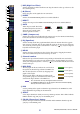
2TR D1L, 2TR D1R...2TR D3L, 2TR D3R L/R channels of 2TR IN DIGITAL jacks 1–3*
2TR A1L, 2TR A1R, 2TR A2L, 2TR A2R L/R channels of 2TR IN ANALOG jacks 1/2*
INPUT CH window
1
2
3