
User Manual

PM5DV2/DSP5D Editor Owner’s Manual
9
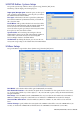
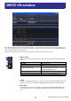
D HPF (High Pass Filter)
Switches the high pass filter on/off. You can drag the numeric value up or down to edit
the cutoff frequency.
E Ø (Phase)
Inverts the phase of the signal after AD conversion.
F INSERT
Switches the INSERT PATCH path between enabled/disabled.
G DIRECT
Switches the output to the DIRECT OUT PATCH port between enabled/disabled.
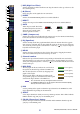
H GATE
Turns the gate on/off. The indica-
tor immediately below the button
shows the gate’s on/off setting
and the open/closed status.
I COMP (Compressor)
Switches the compressor on/off. When the compressor is on, the GR meter immediately
below the button shows the amount of gain reduction.
J EQ (Equalizer)
Switches the EQ on/off. The graph immediately below the button shows the approxi-
mate response of the EQ. You can drag within the graph to edit the response of the EQ.
To reset the EQ to flat response, hold down the <Ctrl> key ( key) of your computer
keyboard and click the graph.
K DELAY
Switches the delay on/off. You can also edit the delay time by dragging the numeric
value located immediately below the button up or down
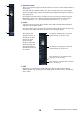
L Channel number
Indicates the input channel number corresponding to this module. You can double-
click this number to open the Selected Channel window for this channel. If you hold
down your computer keyboard’s <Ctrl> key ( key) and double-click this, the Locked
window will open.
M MIX SEND
The bar graphs in this area indicate the send levels of
the signals sent from the input channel to MIX buses.
You can also adjust the send levels by dragging a bar
graph to left or right.
The bar graph display will change according to the
send position (pre/post) and on/off status of the signal
sent from the input channel to the MIX buses.
•You can turn this on/off by clicking the number at the left.
•For FIXED-type MIX buses, the bar graph is fixed at nominal level (0 dB),
and only the on/off status is shown.
N PAN
Sets the panning of the signal sent from the input channel to the STEREO bus. This
may be BALANCE depending on the PAN mode.
O SELECT
Selects input channel for which you want to perform operations. This is linked with the
INPUT channel strip [SEL] keys on the PM5D panel.
P CH ON (Channel on) button
Switches the input channel on/off. This is linked with the INPUT channel strip CH
[ON] keys on the PM5D panel.
L
O
P
N
M
5
6
7
8
9
J
4
K
Gate= closed
(red)
Gate= open
(green)
Gate= off
Pre/on (green)
Pre/off (green)
Post/off (yellow)
Post/on (yellow)
NOTE