PM5DV2/DSP5D Editor Owner’s Owner’s Manual Manual ❏ Special Notices • The software and this owner’s manual are the exclusive copyrights of Yamaha Corporation. • Copying of the software or reproduction of this manual in whole or in part by any means is expressly forbidden without the written consent of the manufacturer. • Copying of the commercially available music sequence data and/or digital audio files is strictly prohibited except for your personal use.
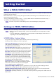
Getting Started What is PM5D/DSP5D Editor? PM5D Editor and DSP5D Editor allow you to remotely control the parameters of the PM5D or DSP5D, and save the parameters on your computer. PM5D/DSP5 Editor are used by starting them up from within Studio Manager. To use PM5D/DSP5D Editor, you must perform the following steps. “Start up Studio Manager and make settings” → “Start up PM5D Editor or DSP5D Editor and make settings” → “Synchronize with the PM5D/DSP5D itself (➥ p.
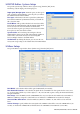
❏ DSP5D Editor: System Setup To open the System Setup window, choose [System Setup] from the [File] menu. You must specify the Input port and Output port. Input port/Output port: From the ports you have previously specified in Studio Manager, select the ports you will use for communication with the DSP5D. Fast Sync: This shortens the time required for synchronization with the DSP5D. If synchronization fails, you should disable (clear) this item.
Number of Effects: This changes the number of assigned internal effects and GEQ modules. Decreasing the number of internal effects by one will increase the number of available GEQ modules by one. You can change the number assigned between eight internal effects (and twelve GEQ modules) to no internal effects (and twenty GEQ modules). You can use up to eight GEQ modules as effects. +48V Master: This function is found only in DSP5D Editor.
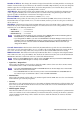
Synchronizing PM5D/DSP5D Editor When PM5D/DSP5D Editor starts up, the parameter settings on the PM5D/DSP5D itself and the parameter settings in PM5D/DSP5D Editor may be different. Therefore, you must first match the parameter settings on the PM5D/ DSP5D itself with those in PM5D/DSP5D Editor. This operation is called “synchronization.” Follow the steps below to synchronize PM5D/DSP5D Editor. 1 Select [Synchronize], then [Re-synchronize]. The window shown at right opens.
If you save a Session in the Studio Manager window, all selected Editor settings are saved in a file with a file extension of “.YSM.” NOTE Data with the extension “.PM5” that was saved by PM5D version 1 and PM5D Editor (supporting version 1) can also be opened by PM5DV2 Editor. Window operations You can select and open each window from the [Windows] menu. For the INPUT CH window and Effect Editor window, use the sub-menu to select the channels or library you want to see.
Undo/Redo Function In PM5D/DSP5D Editor, you can cancel the latest operation (Undo) and also cancel the cancellation of the latest operation (Redo). If you perform an Undo operation twice in a row, you can cancel the two most-recent operations. If you perform an Undo operation three times in a row, you can cancel the three most-recent operations. In this way, you can cancel multiple recent operations. The following table describes how to use the Undo/Redo function.
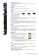
INPUT CH window This window displays the parameters of input channels 1–24 or 25–48. The window shows either the channel 1–24 layer or the channel 25–48 layer. To open the other layer’s window, choose the [Windows] menu command [INPUT CH] and choose “CH1-24” or “CH25-48.” You can use the [View] menu to choose the parameters that will be displayed in the window. 1 2 3 A Input patch Here you can select an input source to assign to the input channel, from the following choices.
4 5 6 7 8 9 J D HPF (High Pass Filter) Switches the high pass filter on/off. You can drag the numeric value up or down to edit the cutoff frequency. E Ø (Phase) Inverts the phase of the signal after AD conversion. F INSERT Switches the INSERT PATCH path between enabled/disabled. G DIRECT Switches the output to the DIRECT OUT PATCH port between enabled/disabled. H GATE K L Turns the gate on/off. The indicator immediately below the button shows the gate’s on/off setting and the open/closed status.
Q R Q Channel name This is a text box that displays the channel name. You can also edit the channel name in this text box. Note that while the channel number (L) does not change when you switch pairing mode in the Mixer Setup window, the channel name display will change according to the pairing mode. For example if the CH1-24 layer is displayed, and you switch the pairing mode from Horizontal to Vertical, the channel name indications that had been arranged in the order of channels 1, 2, 3 ...
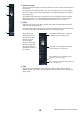
ST IN window In this window you can view and edit the parameters of ST IN channels 1–4. You can use the [View] menu to choose the parameters that will be displayed in the window. 1 2 A Input patch Selects the input source that will be assigned to the ST IN channel. The input sources that can be assigned are the same as for an input channel (➥ p.8).
8 9 J H GATE Turns the gate on/off. The indicator immediately below the button shows the gate’s on/ off setting and the open/closed status (➥ p.9). I COMP (Compressor) Switches the compressor on/off. When the compressor is on, the GR meter immediately below the button shows the amount of gain reduction. K L J EQ (Equalizer) Switches the EQ on/off. The graph immediately below the button shows the approximate response of the EQ.
FX RTN window In this window you can view and edit the parameters of FX RTN channels 1–4. You can use the [View] menu to choose the parameters that will be displayed in the window. 1 2 A Input patch Selects the input source that will be assigned to the FX RTN channel. The input sources that can be assigned are the same as for an input channel (➥ p.8).
7 G Channel number This is the number of the FX RTN channel for this module. You can double-click this number to open the Selected Channel window for this channel. If you hold down your computer keyboard’s key ( key) and double-click this, the Locked window will open. H MIX SEND 8 The send levels of the signals sent from the FX RTN channel to the VARI-type MIX buses are shown as bar graphs (the L/R settings are linked). You can also adjust the send levels by dragging a bar graph to left or right.
MIX window In this window you can view and edit the parameters of MIX channels 1–24. You can use the [View] menu to choose the parameters that will be displayed in the window. 1 2 3 4 5 A EQ (Equalizer) Switches the EQ on/off. The graph immediately below the button shows the approximate response of the EQ. You can drag the graph to edit the response of the EQ, or hold down the key ( key) of your computer keyboard and click the graph to reset it to a flat response.
F MTRX (Send level to MATRIX buses) 6 7 8 9 J K L These bar graphs indicate the send levels of the signals sent from the MIX channel to each MATRIX bus. You can also adjust the send levels by dragging a bar graph to left or right. The bar graph display will change as follows according to the send position (pre/post) and on/off status of the signal sent from the MIX channel to the MATRIX buses.
MATRIX window In this window you can view and edit the parameters of MATRIX channels 1–8. You can use the [View] menu to choose the parameters that will be displayed in the window.
A MIX (Send levels from the MIX channels to the MATRIX bus) Here you can view and edit the send levels of the signals sent from each MIX channel to the MATRIX bus. The method of operation and the meaning of the display are the same as for (6) MTRX in the MIX window (➥ p.16). B STEREO (Send levels from the STEREO channels to the MATRIX bus) 1 Here you can view and edit the send levels of the signals sent from the STEREO A/B channels to the MATRIX bus.
STEREO window In this window you can view and edit the parameters of the STEREO A/B channels. You can use the [View] menu to choose the parameters that will be displayed in the window.
1 2 3 4 5 A EQ (Equalizer) Switches the EQ on/off. The graph immediately below the button shows the approximate response of the EQ. You can drag the graph to edit the response of the EQ, or hold down the key ( key) of your computer keyboard and click the graph to reset it to a flat response. B COMP (Compressor) Switches the compressor on/off. When the compressor is on, the GR meter immediately below the button shows the amount of gain reduction.
DCA window In this window you can view and edit the parameters of DCA groups 1–8. 1 2 3 A DCA number This is the number of the DCA group. B MUTE This switches DCA group muting on/off. This is linked with the DCA [MUTE] keys in the DCA strip section of the PM5D panel. C DCA group name This is a text box that displays the DCA group name. You can also edit the DCA group name in this text box. 4 5 D DCA fader This fader adjusts the level of the DCA group.
Selected Channel window Here you can set the parameters of the currently selected input channel (input channels 1–48, ST IN channels 1–4, FX RTN channels 1–4) or output channel (MIX channels 1–24, MATRIX channels 1–8, STEREO A/B channels). The type of parameters that can be edited in this window will depend on the type of the currently selected channel.
❏ HA GAIN/Ø/HPF (HA gain/phase/high-pass filter) 1 2 3 A HA GAIN Adjusts the gain of the internal HA (PM5D-RH model and DSP5D only) or of the external HA (AD8HR, AD824) patched to the input channel. The current setting is shown in the numerical box above the knob. You can also use the +48V button to switch phantom power on/off. You can use the GANG button to link the gain of two channels that are patched adjacent to each other, so that their current offset value will be maintained.
F DECAY (Decay time) Specifies the time over which the gate will close after the hold time has elapsed. G ATTACK (Attack time) Specifies the time from when the key-in signal exceeds the threshold level until the gate opens. H HOLD (Hold time) Specifies the time that the gate will remain open after the key-in signal falls below the threshold. I ON (On/off) This button switches the gate on/off. J LIBRARY This button accesses the gate library.
❏ COMPRESSOR (except for FX RTN channels) 1 2 4 3 6 5 9 K J 8 7 M L N A Compressor graph Indicates the approximate response for the compressor of the currently selected channel. B GR meter This meter indicates the amount of gain reduction produced by the compressor. C TYPE Indicates the type of the currently selected compressor. D THRESHOLD (Threshold level) Specifies the threshold level at which the compressor will operate.
M COMP LINK GROUP (Compressor link group) Selects the compressor link group (1–8) to which that channel belongs. N KEY IN Selects the signal that will be used as the key-in signal. The types of signal that can be selected are the same as for the gate key-in signal (➥ p.24). ❏ INSERT (except for FX RTN channels) 1 2 3 4 5 A HA GAIN (head amp gain) and +48V Here you can adjust the HA gain for the input (if it has HA) that is patched to INSERT IN, and turn +48V on/off.
❏ EQUALIZER 2 1 8 7 6 3 4 5 J 9 K M L N A EQ graph Indicates the approximate response for the EQ of the currently selected channel. B FLAT If you click this button, the gain of all bands will be reset to 0.0 dB. CQ D F (Frequency) E GAIN These knobs adjust the Q, center frequency, and boost/cut amount for the four bands LOW, LO-MID, HI-MID, and HIGH. F (LOW shelving) If this button is on, the LOW EQ will be switched to a shelving type (the Q knob of the LOW EQ will disappear).
M ATT (Attenuation) Adjusts the amount of attenuation/gain following AD conversion. N GANG If this button is on, the attenuation/gain settings of two adjacent odd-numbered/even-numbered channels will be linked while maintaining the current offset value. ❏ DELAY (except for FX RTN channels) A TIME (Delay time) Adjusts the delay time for each channel. B ON (On/off) Switches the delay on/off. The current value (ms units) is shown in the box at the right.
❏ Pan / Fader A DIRECT (except for FX RTN channels) Turns the direct output on/off. 1 B Direct Output Port (except for FX RTN channels) 2 Choose the port from which this input channel 1–48 or this ST IN channel 1–4 will be directly output. 3 NONE S1-1, S1-2...S4-15, S4-16 4 2TR D1L, 2TR D1R...
❏ CH to MIX (Channel to mix) 2 1 3 4 5 A MIX send level This adjusts the send level of the signal sent from the input channel to VARI-type MIX buses. The current value is shown in the numerical box immediately above. B Pair This indicates the pairing status of adjacent odd-numbered/even-numbered MIX channels. You can click the heart symbol to enable/disable pairing. C ON (MIX send on/off) This is an on/off switch for the signal sent from the input channel to the MIX bus.
If a MIX channel is selected ❏ CHANNEL SELECT (Channel selection) Except for the fact that the operations apply to a MIX channel, and that INPUT PATCH is replaced by OUTPUT PATCH, this is the same as for the channel select area of input channels (➥ p.22). ❏ COMPRESSOR Except for the fact that the COMP LINK GROUP is A–H, and that the types of signal that can be selected for keyin are different, this is the same as for the compressor of an input channel (➥ p.25).
❏ EQUALIZER 2 1 9 8 7 6 3 4 5 K J L M N A EQ graph Indicates the approximate response for the EQ of the currently selected channel. B FLAT If you click this button, the gain of all bands will be reset to 0.0 dB. CQ D F (Frequency) E GAIN These knobs adjust the Q, center frequency, and boost/cut amount for each band. F (LOW shelving) If this button is on, the LOW EQ will be switched to a shelving type (the Q knob of the LOW EQ will disappear).
L TYPE I/TYPE II (EQ type) Selects either TYPE I (an algorithm equivalent to the EQ in the earlier 02R series) or TYPE II (a newly developed algorithm) as the EQ type. M EQ LINK GROUP Selects the EQ link group (A–F) to which that channel belongs. N UPPER/LOWER Switches the four bands affected by controls 3–9 between LOWER (1 LOW–4 HIGH) and UPPER (5 LOW–8 HIGH). ❏ DELAY This is the same as for the delay settings of an input channel (➥ p.28).
❏ Pan / Fader A TO ST (To stereo) This is an on/off switch for the signal sent from the MIX channel to the STEREO bus. The PRE button located below selects PRE (immediately before the MIX [ON] key) or POST (immediately after the MIX [ON] key) as the point from which the signal is sent from the MIX channel to the STEREO bus. B TO ST PAN (To stereo pan) Sets the panning of the signal sent from the MIX channel to the STEREO bus. C LCR 1 Turns LCR mode on/off for each channel.
❏ MIX to MATRIX 2 1 3 4 5 A MATRIX send level This adjusts the send level of the signal sent from the MIX channel to the MATRIX buses. B Pair This indicates the pairing status of adjacent odd-numbered/even-numbered MATRIX channels. You can click the heart symbol to enable/disable pairing. C ON (MATRIX send on/off) This is an on/off switch for the signal sent from the MIX channel to the MATRIX bus.
If a MATRIX channel is selected ❏ CHANNEL SELECT (Channel selection) Except for the fact that the operations apply to a MATRIX channel, and that INPUT PATCH is replaced by OUTPUT PATCH, this is the same as for the channel select area of input channels (➥ p.22). ❏ COMPRESSOR Except for the fact that the COMP LINK GROUP is A–H, and that the types of signal that can be selected for keyin are different, this is the same as for the compressor of an input channel (➥ p.25).
❏ Pan / Fader A BALANCE 1 2 This adjusts the left/right output balance of paired channels. This is not shown if pairing is not specified. B ON This switches the MATRIX channel on/off. This is linked with the MATRIX [ON] keys in the MATRIX section of the PM5D panel. C Fader 3 This adjusts the output level of the MATRIX channel. This is linked with the MATRIX encoders in the MATRIX section of the PM5D panel. The current value is shown in the numerical box immediately below.
❏ COMPRESSOR Except for the fact that the COMP LINK GROUP is A–H, and that the types of signal that can be selected for keyin are different, this is the same as for the compressor of an input channel (➥ p.25). ❏ INSERT Except for the fact that the insert points that can be selected are different, this is the same as for the insert settings of an input channel (➥ p.26). ❏ EQUALIZER This is the same as the equalizer settings of a MIX channel (➥ p.32).
❏ STEREO to MATRIX 2 1 3 4 A MATRIX send level Here you can adjust the send levels of the signals sent from the STEREO A/B channels to the MATRIX bus. B Pair This indicates the pairing status of adjacent odd-numbered/even-numbered MATRIX channels. You can click the heart symbol to enable/disable pairing. C ON (MATRIX send on/off) This is an on/off switch for the signal sent from the STEREO A/B channel to the MATRIX bus.
Patch Editor window Here you can assign the input/output port for each channel, its direct output, and its insert-in/out. This window is divided into INPUT PATCH, OUTPUT PATCH, INPUT INSERT PATCH, OUTPUT INSERT PATCH, DIRECT OUT PATCH, and PATCH LIST pages. To switch pages, click the tabs shown in the upper part of the window. INPUT PATCH page Here you can select the input port that is assigned to the input of each input channel.
OUTPUT PATCH page Here you can select the output port that is assigned to the input of each output channel. Except for the fact that you can resize the window, the basic operation is the same as in the PM5D’s OUTPUT PATCH screen. INPUT INSERT PATCH page Here you can assign input/output ports to the insert-in/out of each input channel. Select the output port in the left side of the screen, and the input port in the right side of the screen.
OUTPUT INSERT PATCH page Here you can assign input/output ports to the insert-in/out of each output channel. Select the output port in the left side of the screen, and the input port in the right side of the screen. Except for the fact that you can resize the window, the basic operation is the same as in the PM5D’s OUTPUT INSERT PATCH screen. DIRECT OUTPUT PATCH page Here you can select the output port that will directly output each input channel.
PATCH LIST page Here you can view and edit the input patch and output patch settings. Input patch, output patch, and channel name data that was written to a CSV file by the PM5D itself can also be loaded into this page. Conversely, the settings in this page can be written to a CSV file that can be loaded into the PM5D. NOTE • VIRTUAL SOUNDCHECK is a display-only function. • In DSP5D Editor, VIRTUAL SOUNDCHECK will be lit only if you operate the PM5D with the PM5D and DSP5D connected.
5 1 6 2 3 4 A Input channel number Input channel name This is the number and name of the input channel. You can click the channel name box to edit the name in this page. B Input port This shows the input port assigned to the input channel. You can click this box and choose the input port from the popup menu that appears. C Output channel number Output channel name This is the number and name of the output channel. You can click the channel name box to edit the name in this page.
Surround Editor window Here you can make surround panning settings for the two currently selected input channels. 1 2 3 4 5 A SELECT (Channel selection) This area displays the name and number of the two channels selected for operations (two adjacent odd-numbered/even-numbered input channels, a ST IN channel, or an FX RTN channel). To switch channels, use the SELECT button or the / buttons at left and right. You can also edit the channel name in the text box.
8 9 J 6 7 K F DIVERGENCE These controls specify the proportion at which the signals are sent to each surround bus when the input channel is positioned in the center. The operable parameters will change as follows, according to the surround mode that is currently selected. • Surround mode= 3-1ch/5.1ch The Div knob will be operable, allowing you to adjust the front divergence.
GEQ window In this window you can select the insertion destination of GEQ modules 1–20, and edit the parameters. The number of GEQ modules will depend on the “Number of Effects” setting specified in the Mixer Setup window. 1 2 3 4 5 6 A MODULE (Module selection) Selects the GEQ module that you want to edit or view. B GEQ/PEQ (GEQ/PEQ select button) This switches the module between GEQ operation or PEQ operation.
For GEQ 7 9 8 J G GEQ graph This graph shows the response of the currently selected GEQ module. H GEQ faders These faders cut/boost the frequency bands of the GEQ module. The value of each fader is shown in the numerical box below it. I LIMIT The range and direction of adjustment controlled by the faders can be selected from the following: ±15 dB, ±12 dB, ±6 dB (these are valid in both the boost and cut directions), or –24 dB (valid only in the cut direction).
For PEQ K O P L M N Q R K PEQ graph This graph shows the response of the currently selected module. L HPF (High Pass Filter) button If this button is on, band 1 or 5 will change to a high-pass filter. The Q knob for 1 or 5 will disappear, and the GAIN knob will operate as a switch that turns the high-pass filter on/off. M Low Shelving button If this button is on, band 1 or 5 will change to a shelving-type filter. (The Q knob for 1 or 5 will disappear.
Effect Editor window Here you can select the effect type for internal effects 1–8, edit the parameters, and specify the input/output patching. The number of available effects can be specified in the Mixer Setup window. NOTE You can also open multiple Effect Editor windows to simultaneously view the settings of different-numbered internal effects. However, the parameters of the unit itself will change in tandem with parameter operations in the window only in Effect Editor windows that are not [Locked].
EEffect parameters This area shows the effect parameters and knobs for the currently selected effect type. 5 6 7 8 9 F Input meter Indicates the level of the signal being input to the internal effect. G Input patch Click the L CHANNEL or R CHANNEL area, and choose one of the following as the signal route that will be patched to the L/R input channels of the internal effect. NONE MIX 1...MIX 24 INS CH1...INS CH48 INS STIN1L, INS STIN1R...INS STIN4L, INS STIN4R INS MIX1...INS MIX24 INS MTRX1...
H Output meter Indicates the level of the signal being output from the internal effect. I Output patch Click the L CHANNEL or R CHANNEL area, and choose one of the following as the signal route that will be patched to the L/R output channels of the internal effect. NONE CH 1...CH 48 STIN1L, STIN1R...STIN4L, STIN4R FXRTN1L, FXRTN1R...FXRTN4L, FXRTN4R INS CH1...INS CH48 INS STIN1L, INS STIN1R...INS STIN4L, INS STIN4R INS MIX1...INS MIX24 INS MTRX1...
M O N P Q M MIX BALANCE Adjusts the balance of the effect sound relative to the original sound. 0 (%) outputs only the original sound, and 100 (%) outputs only the effect sound. N BYPASS This button temporarily bypasses the effect. O CUE This button cue-monitors the output of the currently selected effect. P TEMPO If a tempo-type or modulation-type effect is selected, this allows you to adjust time-related parameters such as DELAY (delay time) and FREQ. (modulation speed).
DCA/Mute Group window In this window you can select the channels that will be assigned to each DCA group and mute group. This window is divided into two pages; the DCA GROUP ASSIGN page and the MUTE GROUP ASSIGN page. DCA GROUP ASSIGN page Here you can specify the channels that will be assigned to DCA groups 1–8. The upper part of the screen lets you assign input channels to DCA groups, and the lower part of the screen lets you assign output channels to DCA groups.
C Grid This grid lets you assign channels (horizontal rows) to DCA groups (vertical columns). Currently-patched grids are indicated by a symbol. To enable or disable an assignment, click the desired grid. D CLEAR These buttons clear all input channels and output channels assigned to the corresponding DCA group. When you click one of these buttons a window will appear, asking you to confirm the operation. To execute the Clear operation, click the OK button.
1 2 3 5 4 A Mute group This area shows the mute group number. B MUTE MASTER (Mute master) These buttons turn muting on/off for each mute group (common to inputs and outputs). C Grid This grid lets you assign channels (horizontal rows) to mute groups (vertical columns). Currently-patched grids are indicated by a symbol. To enable or disable an assignment, click the desired grid. D MUTE SAFE ON (Mute Safe on/off) These buttons switch Mute Safe on/off for each channel.
Scene window Here you can manage scene memories, and make various settings related to scene recall operations. This window is divided into SCENE MEMORY, EVENT LIST, RECALL SAFE, and FADE TIME pages. To switch pages, click the tabs shown in the upper part of the window. SCENE MEMORY page Here you can edit the PM5D/DSP5D’s scene memories. You can also load scene library files from a memory card or from a drive of your computer, and edit them.
F FILE This area lists the scenes in the file you opened using the OPEN button ( 1). The list includes the following items. HINT 7 To view items that are not currently shown, scroll the list to the right. The boundary lines in the center of the window can be dragged toward the right to expand the file list display area as shown below. 8 9 J K G No. (Scene number) This is the scene number 000–500. (The FILE side will begin from 001.) H TITLE This is the scene title.
N MIDI EVENT This function is found only in PM5D Editor. In this column, the MIDI event that is transmitted from the MIDI OUT connector when the scene is recalled can be viewed and edited in hexadecimal form. To edit a MIDI event, click the two-digit hexadecimal value you want to edit, and choose the desired value from the popup menu that appears. HINT • If you choose “NOP” from the popup menu, that two-digital hexadecimal value will be ignored.
T U S V W X S INTERNAL DATA This area shows the PM5D/DSP5D’s scene memory contents. The items displayed are the same as in the FILE list (6). As desired, you can copy single or multiple scenes between the FILE list and the INTERNAL DATA list, and copy or move them to a different location within a list. To do this, use the following methods to select the scene(s) that you want to copy or move. • To select a single scene Click the line containing the desired scene.
• To copy scenes (overwriting the destination) Drag the copy-source scene(s) to the desired line in the other list or to another line in the same list. At this time, a ® symbol will appear at the right of the scene number. When you release the mouse in this state, a dialog box will appear, asking you to confirm the Save operation. If you click the OK button, the copy-source scene(s) will be overwritten onto the copy-destination scenes, and the copy-source scene(s) will remain unchanged.
EVENT LIST page In this page you can see how the scenes registered in the PM5D’s EVENT LIST screen will be switched according to the progression of time code or according to the elapsed time since the most recent Recall operation. NOTE • This page functions as a viewer of the PM5D’s EVENT LIST screen. You cannot register or recall events from within this page.
SELECTIVE RECALL page Here you can make settings for the Selective Recall function, which allows you to exclude specific parameters/channels of each scene from recall operations, or conversely to recall only specific parameters/channels. Display and operations within this page are the same as in the SELECTIVE RECALL screen of the PM5D itself. RECALL SAFE page Here you can make settings for the Recall Safe function that excludes only specific channels from recall operations of all scenes.
FADE TIME page Here you can make settings for the Fade function that adjusts the time over which fader and pan will reach their new values when a scene is recalled. The settings of the Fade function are independent for each scene. 1 2 A FADING ENABLE (Fade function enable/disable) Switches the Fade function for fader levels between enabled and disabled.
3 4 5 C SET ALL This button lets you enable all Fade function settings with one click. This can be operated independently for all input channels and DCA groups, or for all output channels. D CLEAR ALL This button lets you disable all Fade function settings with one click. This can be operated independently for all input channels and DCA groups, or for all output channels.
Library window Here you can edit the PM5D/DSP5D’s various libraries. You can also load library files that were saved on a drive of your computer, edit the order or title of library items, recall the desired library data, or copy desired library data to a library within the PM5D/DSP5D. This window is divided into INPUT CH, OUTPUT CH, GATE, COMP, INPUT EQ, OUTPUT EQ, INPUT PATCH, OUTPUT PATCH, EFFECT, GEQ, and HA pages; to switch pages, click the tabs located at the top of the window.
7 8 9 K L M N O J P Q G No. (Number) This area shows the library number. H TITLE This column indicates the title assigned to each library item. You can also double-click this area and edit the title. I READ ONLY Read-only data is indicated by “READ” displayed in this column. If the PREFERENCE screen LINKED LIBRARY PROTECTION is also protecting the library (INPUT PATCH/ OUTPUT PATCH/HA) that is linked to a protected scene, a lock icon is shown in this field.
P CLEAR Clears the data item(s) selected in the list. (The title of the cleared item(s) will be reset to [ No Data! ].) Q UNDO Cancels the last-performed library store, copy, or move operation. Meter window Here you can view the signal levels within the PM5D/DSP5D, or the amount of gain reduction produced by the internal compressors and gates. This lets you check signal presence, overload status, and compressor/gate operation from your computer.
Timecode Counter window This window displays the time code (LTC, MTC) that the PM5D itself is receiving or generating, in units of hours/minutes/seconds/frames. This is the same time code as displayed in the PM5D’s fixed display screen and in the EVENT LIST screen. NOTE • The DSP5D does not have this function. • In order for the Timecode Counter window to display the time code that the PM5D itself is receiving/ generating, PM5D Editor and the PM5D must be synchronized.
Preference window In this window you can make PM5D/DSP5D preference settings. Choose [Windows] → [Utility] → [Preference] to access this window. 1 2 6 3 4 7 5 A STORE/RECALL Here are on/off switches for options related to storing and recalling scenes. You can specify the following options. • LINKED LIBRARY PROTECTION If this button is on, it will not be possible to overwrite or delete a library that is linked to a protected scene.
D DCA MUTE TARGET When the send position to the MIX bus is PRE FADER, this specifies whether the DCA [MUTE] keys will mute the send to the MIX bus. If you specify “POST ONLY,” the PRE FADER signal will not be muted. If you specify “PRE & POST,” the signal will be muted regardless of the send position. E WARNING DISPLAY This selects whether a warning will be displayed when the following problems occur. • TIME CODE DROP This function is found only in PM5D Editor.
User Defined Keys Setup window In this window you can assign functions to the PM5D console’s user-defined keys from within the editor. Choose [Windows] → [Utility] → [User Defined Keys Setup] to access this window. DSP5D Editor does not have a corresponding window. When you click the button for the desired user-defined key, an editing screen will appear, allowing you to assign a function. However unlike operations on the PM5D itself, you won’t be able to execute the assigned function.
Fader Mode Assign window In this window of the editor you can freely assign functions to the faders just as in the PM5D’s FADER ASSIGN screen. Choose [Windows] → [Utility] → [Fader Mode Assign] to access this window. However unlike the FADER ASSIGN screen on the PM5D itself, you won’t be able to execute the assigned function. If you synchronize Console -> PC, the settings of the console will be reflected in PM5D Editor. DSP5D Editor does not have a corresponding window.
Word Clock window In this window of the editor you can edit and view the DSP5D’s word clock settings. Choose [Windows] → [System] → [Word Clock] to access this window. DSP5D Editor does not have a corresponding window. 1 2 3 A MASTER CLOCK SELECT This selects the master clock that will be used; either the internal clock or an external clock received via a connector or slot. This setting will determine the sampling rate at which the DSP5D will operate. You can select the following items.
• UNLOCK ( ) This indicates that a valid clock is not being input. If an external device is connected to the corresponding connector, input/output cannot occur correctly between that device and the DSP5D. • LOCK, but NOT SYNC’ED ( ) A valid clock is being input, but is not synchronized with the clock source selected in 1. If an external device is connected to the corresponding connector, input/output cannot occur correctly between that device and the DSP5D.
• DITHER This indicates the number of bits for which dithering will be applied to the input signal, in units of two channels. When you click this with the mouse, a popup will appear, allowing you to select either OFF, 16 bit, 20 bit or 24 bit. Select the desired number of bits for dithering.
Oscillator window In this window of the editor you can edit and view the DSP5D’s oscillator status. Choose [Windows] → [Monitor] → [Oscillator] to access this window. PM5D Editor does not have a corresponding window. 1 2 3 For SINE WAVE 2CH For PINK NOISE For BURST NOISE A OSC ON/OFF (oscillator on/off) This switches the oscillator on/off. B OSC MODE (oscillator mode) Here you can select from the following choices of waveform or noise that the oscillator will produce. SINE WAVE 1CH .......
• HPF (high pass filter) / LPF (low pass filter) Here you can make settings for the HPF/LPF that will process the pink noise or burst noise. The upper knob sets the cutoff frequency (20 Hz–20 kHz), and the lower button turns it on/off. • WIDTH/INTERVAL If burst noise is selected, these specify the length of the actual noise (WIDTH), and the length of the silent interval between noise bursts (INTERVAL). The range for WIDTH is 0.1–10 sec, and the range for INTERVAL is 1–30 seconds.
Cue/Solo window In this window of the editor you can edit and view the cue and solo status of the PM5D/DSP5D. Choose [Windows] → [Monitor] → [Cue/Solo] to access this window. 4 5 6 1 2 9 3 K L 7 8 J A SOLO ON/OFF This button selects either CUE MODE or SOLO mode as the monitoring method when the [CUE] key is used. If you turn this button on, a confirmation message will appear. Each mode operates as follows.
• LAST CUE mode Only the channel or DCA group that was most recently selected by its [CUE] key will be monitored. C CUE FUNCTION Here you can turn various cue-related functions on/off. The following functions are available. • MIX CUE LINK This specifies whether cue operation will be linked with MIX channel selection. If this button is on, pressing the already-selected [MIX] key in the panel ENCODER MODE section will simultaneously cause the [CUE] key of that channel to light.
H OUTPUT SOLO SAFE Here you can select the output channels that will be excluded from solo operations (multiple selections are allowed). These buttons correspond to the following output channels. MIX 1–24 MATRIX 1–8 STEREO A/B SET ALL CLEAR ALL HINT MIX channels 1–24 MATRIX channels 1–8 STEREO A/B channels Activates solo safe for all output channels Defeats solo safe for all output channels Solo safe settings and cue on/off settings are linked for two paired channels.
Port Trim window PM5D Editor does not have a corresponding window. Here you can make fine adjustments to the AD input/output gain. As necessary, make fine adjustments to the gain of the specified analog input/output port. You can adjust this in 0.1 dB units for input ports, and in 0.01 dB units for output ports. When the unit is shipped from the factory, the input levels of each port are set to match, so there is normally no need to adjust this.
Keyboard Shortcuts Menu File menu Action Windows Mac Creates a new Session Ctrl+N +N Opens a previously saved Session Ctrl+O +O Saves the current Session Ctrl+S +S Undo Ctrl+Z +Z Redo Ctrl+Y +Y Ch Copy Ctrl+C +C Ch Paste Ctrl+V +V Closes the active window Ctrl+W +W Closes all windows Ctrl+Alt+W +Option+W Opens the Sync window Ctrl+1 +1 Opens the INPUT CH (CH1-24) window Ctrl+2 +2 Opens the INPUT CH (CH25-48) window Ctrl+Alt+2 +Option+2 Opens the Selected Channel wind
Index Symbols +48V Master .................................... 4 A ALL INPUT CHANNEL ................ 64 B Bus Setup .......................................... 3 BYPASS .......................................... 53 C Cascade Connection ........................ 4 CH to MIX ..................................... 30 Channel to mix .............................. 30 CLEAR ...................................... 61, 68 CLEAR ALL .................................... 65 CLOSE ......................................
S U SAME AS FADING ........................ 64 SAVE ........................................ 57, 66 SAVE AS ................................... 57, 66 Save as a different name .......... 57 Save under a different name .... 66 SCENE MEMORY page ................ 57 Scene window ................................ 57 EVENT LIST page .................... 62 FADE TIME page ..................... 64 RECALL SAFE page ................. 63 SCENE MEMORY page ........... 57 SELECTIVE RECALL page ...... 63 SEL ..........