
User Manual


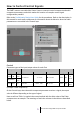
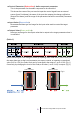
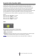


Table Of Contents
- Introduction
- Audio Components
- The Difference Between Mono, Stereo, and Multi
- How to Control Control Signals
- Acoustic Echo Canceller (AEC)
- Ambient Noise Compensator (ANC)
- Audio Detector
- Auto Gain Control (AGC)
- Combiner
- Room Combiner/Room Combiner plus Automixer
- ■ “Room Combiner” component editor/”Room Combiner plus Automixer” component editor
- ■ “Room Combiner” component editor/”Room Combiner plus Automixer” component editor
- Combiner parameter setting window (Room Combiner)
- Combiner parameter setting window (Room Combiner plus Automixer)
- Control
- Control
- Dugan Automixer window (Room Combiner plus Automixer)
- Room Combiner/Room Combiner plus Automixer
- DCA
- Delay
- Dynamics
- REV-X
- EQ
- Fader
- Feedback Suppressor
- Filter
- Input/Output
- Meter
- Mixer
- Oscillator
- Polarity
- Probe
- Router
- Source Selector
- Speaker Processor
- Control Components
- Control Methods for Control Components
- Trigger
- Button (Normalized Value)
- Button (Value)
- Radio Button (Normalized Value)
- Radio Button (Value)
- Fader (Normalized Value)
- Fader (Value)
- Processing
- Logic (Normalized Value)
- NOT (Normalized Value)
- Flip-Flop (Normalized Value)
- Invert (Normalized Value)
- Compare (Normalized Value)
- Difference (Normalized Value)
- Max/Min (Normalized Value)
- Negate (Value)
- Compare (Value)
- Multi Compare (Value)
- Difference (Value)
- Max/Min (Value)
- Delay
- External Events
- Suspend
- Router
- Other
- GPI In
- GPI Out

ProVisionaire Design DME7 Component Guide
6
● Control Parameter (Red outline): Audio component parameter
This is the parameter for the audio component to be controlled.
This shows the name of the port used to input the control signal from an external
source (Input Port Name), the name of the port that outputs the change notification
(Output Port Name), and the range of the parameter that will be controlled (Parameter
range).
● Input Value (Blue outline):
Recommended data type and range for the input value used to control the target
parameter.
● Output Value (Green outline):
Data type and range for the output value that is output to the target parameter when it
is controlled.
(Table 1)
When controlling the Level using the Fader, by inputting either a dB value (–∞ to 10.00) of
the same data type as the Level parameter you want to control, or inputting a normalized
value (0.00 to 1.00), the Fader Level can be controlled in the range of –∞ to 10.00. (Fig. 1)
Conversely, by changing the Level of the Fader, a dB value (–∞ to 10.00) is output. (Fig. 2)
Fig. 1 Fig. 2
Audio Component Audio Component
–
–
–
–
–