CL/QL series V4.1 Supplementary Manual This supplementary manual explains mainly the functions that have been added or changed in CL5/CL3/CL1 and QL5/ QL1 firmware V4.1. Use it in conjunction with the CL5/CL3/CL1 and QL5/QL1 V4 Owner’s Manual and Reference Manual. CL/QL Editor V4.1 Supplementary Manual This supplementary manual explains mainly the functions that have been added or changed in CL/QL Editor V4.1. NOTE • The explanations in this supplementary manual will use the CL5.
Contents Contents Support for Shure AXT400, QLXD4 and ULXD4........................ 3 Selected Channel section (QL series only) .............................. 11 4-band EQ band selection...................................................................................... 11 Input and output patching..................................................... 12 Added functions to display channel name and effect type in the PATCH/NAME window, CH SELECT window, and PORT SELECT window...........................
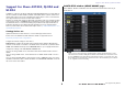
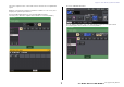
Support for Shure AXT400, QLXD4 and ULXD4 Support for Shure AXT400, QLXD4 and ULXD4 DANTE SETUP window (DEVICE MOUNT page) Shure AXT400, QLXD4, and ULXD4 can be mounted in this window in the same way as Dante devices. In addition to support for the Shure ULXD4D and ULXD4Q digital wireless systems with CL/ QL V4.0 and later, the Shure AXT400, QLXD4, and ULXD4 wireless systems, which do not feature Dante output, can now be controlled.
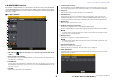
Support for Shure AXT400, QLXD4 and ULXD4 DEVICE SELECT window (when DEVICE LIST is displayed) DEVICE SELECT window (when SUPPORTED DEVICE is displayed) 1 NOTE If a device has the DEVICE IDENTIFY function, the DEVICE IDENTIFY button is enabled. Otherwise, this button will be grayed out and cannot be pressed. 1 I/O device indication (for devices that do not feature Dante output) “NO DANTE PORT” appears on the right side. NOTE If a device does not feature Dante output, offline mounting is not possible.
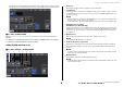
Support for Shure AXT400, QLXD4 and ULXD4 9 RF (Radio Frequency) signal meter I/O DEVICE window (WIRELESS page) Shows bars to indicate the level of the RF signal. An active antenna indicator is shown on the right side. It indicates which antenna is enabled. For Shure AXT400 A 1 2 NOTE For details about the relationship between the number of bars and the actual strength of the RF signal, refer to the manual from Shure.
Support for Shure AXT400, QLXD4 and ULXD4 5 Channel name (receiver) I/O DEVICE EDIT window Press this button to open the NAME window to set the channel name for the receiver. You can enter up to 8 characters. The channel name that is set on the transmitter is displayed. This window is displayed when you select and press the wireless device in the I/O DEVICE window (WIRELESS page). Set the channel name, GAIN, and other settings. These settings cannot be configured when the console is offline.
Support for Shure AXT400, QLXD4 and ULXD4 This section explains how to control Shure wireless mics that do not output Dante signals. Access the GAIN/PATCH window. Example: Connecting the output of an AXT400 to OMNI 1 on a CL console, and assigning the signal to input channel 1. Press the PORT ASSIGN button to open the PORT SELECT window. Select the port to which the output from the AXT400 is connected (OMNI 1).
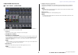
Support for Shure AXT400, QLXD4 and ULXD4 1 Frequency This assigns the output signal from the AXT400 to the input channel, and at the same time allows you to control and monitor the level of the AXT400 from the input channel. Indicates the frequency that is currently set for the RF signal. 2 TX.GAIN knob Sets the gain for the transmitter. To adjust the value, press the knob to select it, and use the multifunction knobs (for CL series consoles) or the TOUCH AND TURN knob (for CL/ QL series consoles).
Support for Shure AXT400, QLXD4 and ULXD4 4 RF (Radio Frequency) signal meter GAIN/PATCH window (8ch) Shows bars to indicate the level of the RF signal (both A and B channels for AXT400). An active antenna indicator is shown on the right side. It indicates which antenna is enabled. For Shure AXT400 / QLXD4/ULXD4 NOTE For details about the relationship between the number of bars and the actual strength of the RF signal, refer to the manual from Shure.
Support for Shure AXT400, QLXD4 and ULXD4 GAIN/PATCH window (1-48, 49-72/ST IN (CL5), 49-64/ST IN (CL3), ST IN (CL1)) and OVERVIEW window SELECTED CHANNEL window For Shure AXT400 / QLXD4/ULXD4 For Shure AXT400 / QLXD4/ULXD4 2 1 1 4 4 2 3 1 TX.GAIN knob (for AXT400) RX.GAIN knob (for QLXD4/ULXD4) 1 TX.GAIN knob (for AXT400) NOTE RX.
Selected Channel section (QL series only) Selected Channel section (QL series only) 4-band EQ band selection Selections of the EQ [LOW] key/EQ [LOW-MID] key/EQ [HIGH-MID] key/EQ [HIGH] key on the top panel and band selections on the touch screen are now linked. 11 V4.
Input and output patching Input and output patching Added functions to display channel name and effect type in the PATCH/NAME window, CH SELECT window, and PORT SELECT window. The channel name and effect type are now displayed below the channel select buttons and port select buttons in the PATCH/NAME window, CH SELECT window, and PORT SELECT window. NOTE In categories other than DANTE IN, channel labels cannot be set in Dante Controller for the following buttons, and therefore they are not displayed.
Input/Output channels Input/Output channels Color name display In the PATCH/NAME window (when the ICON tab is selected), color names are now displayed on the channel color select buttons. 13 V4.
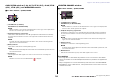
EQ and Dynamics EQ and Dynamics Simultaneously setting EQ type 2 You can now set the EQ type simultaneously for all channels or all racks in the HPF/EQ window or the PEQ EDIT window. You can select channels by category. STEP 1. Press the EQ type select button in the window. 2. Press the GLOBAL SETUP button on the top right side of the popup window. 3. Select an EQ type and channel category in the GLOBAL EQ TYPE window. 4. Press the APPLY button. 5.
EQ and Dynamics HIGH band HPF/EQ window (1ch) • When set to PEQ (Q=0.10), press in and turn the Q knob to the right to switch to shelving type. • When set to PEQ (Q=16.0), press in and turn the Q knob to the left to switch to low-pass filter. • When set to shelving type (Q=10.0), press in and turn the Q knob to the left to switch to PEQ. • When set to low-pass filter, press in and turn the Q knob to the right to switch to PEQ.
Meters Meters Added functions in the RTA display window (RTA METER window, HPF/EQ window, GEQ window, 8BandPEQ window) 1 The visibility of frequency analysis displays has been improved with the addition of a scale change and offset gain, and the addition of PEAK HOLD. 2 1 1 1 Offset gain (RTA METER window, HPF/EQ window, GEQ window, 8BandPEQ window) If a frequency is at a low level, its analysis results might not appear clearly in a graph.
I/O devices and external head amps I/O devices and external head amps I/O DEVICE [OUTPUT PATCH] window Support for the AES67 standard for audio networking interoperability The AES67 standard for interoperability through the use of audio-over-IP technology is now supported. This allows the CL/QL console and R series to establish an audio connection with audio networks that support AES67, such as “Ravenna.
Setup Setup I/O DEVICE window (I/O page) RSio64-D display Added supported devices If the card’s internal sampling rate converter function is enabled when an MY8-AE96S miniYGDAI card is inserted into the RSio64-D, the display will appear as shown below. 1 The following devices are now supported: Audinate Dante-MY16-AUD2; d&b audiotechnik DS10; Shure AXT400, QLXD4, and ULXD4. They can be mounted on the DEVICE MOUNT page in the DANTE SETUP window.
Setup 19 V4.
Setup Dante Device Lock If a device connected to the console is online, and Dante Device Lock is enabled for that device, the LOCKED indicator will appear in each window as shown below. The CL/QL console and R series now support Dante Device Lock. Its status is displayed on CL/QL. Dante Device Lock prevents changes to the Dante audio network settings of a Dante device by another computer on the same network. Dante Device Lock settings are configured in Dante Controller.
Setup Added functions in the NETWORK window If you select DHCP or AUTO IP, the window will appear as shown below and you will be unable to set the IP ADDRESS, SUBNET MASK, and GATE WAY ADDRESS. NETWORK window (FOR DEVICE CONTROL page) Use this window to set the console’s IP address, in order to use the Dante PRIMARY connector on the rear panel to remote-control external devices. DHCP, AUTO IP, and fixed IP settings are supported.
Setup NETWORK window (FOR MIXER CONTROL page) Alert message display Use this window to set the console’s IP address, in order to use the NETWORK connector on the rear panel to remote-control the console from CL Editor/QL Editor, StageMix, or the MonitorMix application. Set the UNIT Name and PIN for the MonitorMix application here. For the IP SETTING MODE select buttons, only STATIC IP button is enabled. The other buttons cannot be selected.
CL/QL Editor V4.1 Supplementary Manual CL/QL Editor V4.1 Supplementary Manual Added specifications for the CSV file read function The number of synonyms and abbreviations that can be used when creating a CSV file have been increased. Reading and Writing CSV files Channel color notation Added option for writing CSV files Original notation You can now set an output format before selecting a folder for writing CSV files. Short format: CL/QL Editor V4.0.0 and V4.0.
Reading and Writing CSV files Channel icon notation Original notation Original notation Notation when reading a CSV file Notation when reading a CSV file Wireless WirelessMic, W/L, W.L Kick BassDrum, B.Dr, BD, B.D Podium Speech, Lecture Snare Sn, S.Dr, Botm, Botom Wedge Foot, Flor, Floor Hi-Hat HiHat, HH 2way Tom RackTom, F.Tom, Ftom, LTom, HTom In-Ear InEar, IEM, Ear Drumkit Drum, Kit, Drums, Top, TopL, TopR, O.HEAD, O.H Effector Fx, Eff, Effect Perc.
Reading and Writing CSV files Port name notation for input patches and output patches Original notation (Normal format) Original notation (Short format) Original notation (Normal format) Original notation (Short format) Additional notation when reading a CSV file * Underlined words can be omitted. * [n] indicates a number (such as a channel number). Additional notation when reading a CSV file * Underlined words can be omitted. * [n] indicates a number (such as a channel number).
Support for devices that do not feature Dante output Original notation (Normal format) Original notation (Short format) Support for devices that do not feature Dante output Additional notation when reading a CSV file * Underlined words can be omitted. * [n] indicates a number (such as a channel number).
Support for devices that do not feature Dante output Overview window (INPUT CH window) When the receiver is off The HA display appears as shown below. AXT400 display When the receiver is on and connected via a ShowLink® remote control The RF level is shown for two channels (A and B). When the receiver is on and not connected via a ShowLink® remote control QLXD4 and ULXD4 display The RF channel (A or B) display has the same design as for the AXT400.
Yamaha Pro Audio global website http://www.yamahaproaudio.com/ Yamaha Downloads http://download.yamaha.