
manual


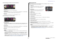


Table Of Contents
- How to Use This Reference Manual
- Contents
- Function Tree
- SELECTED CHANNEL section
- Channel Strip section
- Input and output patching
- Input channels
- Signal flow for input channels
- Specifying the channel name, icon, and channel color
- Making HA (Head Amp) settings
- Sending the signal from an input channel to the STEREO/MONO bus
- Sending a signal from an input channel to a MIX/ MATRIX bus
- Channel name display indication
- Correcting delay between channels (Input Delay)
- Surround output for input channels
- Channel library operations
- OUTPUT channels
- Signal flow for output channels
- Specifying the channel name, icon, and channel color
- Sending signals from MIX channels to the STEREO/ MONO bus
- Sending signals from MIX channels and STEREO/ MONO channels to MATRIX buses
- Correcting delay between channels (Output Delay)
- Using the PORT TO PORT function
- Channel library operations
- EQ and Dynamics
- Channel Job
- Scene memory
- Monitor and Cue functions
- Talkback and Oscillator
- Meters
- Graphic EQ, Parametric EQ, effects, and Premium Rack
- I/O devices and external head amps
- MIDI
- Recorder
- Setup
- About the SETUP screen
- User settings
- Preferences
- USER DEFINED keys
- Functions that can be assigned to USER DEFINED keys
- USER DEFINED knobs
- Functions that can be assigned to USER DEFINED knobs
- Custom fader bank
- Console Lock
- Saving and loading setup data to and from a USB flash drive
- Word clock and slot settings
- Using cascade connections
- Basic settings for MIX buses and MATRIX buses
- Switching the entire phantom power supply on/ off
- Specifying the brightness of the touch screen, LEDs, channel name displays, and lamps
- Setting the date and time of the internal clock
- Setting the network address
- Setting up the Dante audio network
- Using GPI (General Purpose Interface)
- Help function
- Other functions
- Initializing the unit to factory default settings
- Adjusting the detection point of the touch screen (Calibration function)
- Adjusting the faders (Calibration function)
- Fine-tuning the input and output gain (Calibration function)
- Adjusting the LED color (Calibration function)
- Adjusting the brightness of the channel name display
- Adjusting the contrast of the channel name display
- Initializing the Dante audio network settings
- Warning/Error Messages
- Index
- Data List
- Contents
- EQ Library List
- DYNAMICS Library List
- Dynamics Parameters
- Effect Type List
- Effects Parameters
- Premium Rack Processor Parameters
- Parameters that can be assigned to control changes
- NRPN parameter assignments
- Mixing parameter operation applicability
- MIDI Data Format
- Input/Output Specifications
- Electrical characteristics
- Mixer Basic Parameters
- Pin Assignment Chart
- MIDI Implementation Chart

SELECTED CHANNEL section
Reference Manual
10
DIRECT OUT field
This field enables you to make Direct Out settings.
1 Popup button
Press this button to open the INSERT/DIRECT OUT 1ch
window. The Direct Out level value will appear below the
button.
2 ON button
Switches the Direct Out on or off.
RECALL SAFE field
This field enables you to make Recall Safe settings.
1 Popup button
Press this button to open the RECALL SAFE window.
2 ON button
Switches the Recall Safe status on or off.
3 PARTIAL indicator
This will light if recall safe applies only to some of the parameters, not to all channel
settings.
FADER field
This field enables you to make settings for the channel on/off
status and the level.
1 Fader
Displays the current level.
Use the faders on the top panel to set the levels.
2 Level indicator
Displays the current level setting by numerical value. If
the signal is clipping at any point in the channel, the ΣCLIP indicator will light.
3 ON button
Switches the channel on or off. The button is linked with the corresponding [ON] key
on the top panel.
DCA/MUTE field
This field enables you to select the DCA or mute group to which the
channel is assigned.
1 Tabs
Select a DCA or mute group. Press the selected tab once again
to open the DCA/MUTE GROUP ASSIGN MODE window.
When the DCA group tab is selected:
2 DCA group select buttons
Select the DCA group to which the channel is assigned.
3 Mute group indicators
Indicate the mute group to which the channel is assigned.
When the mute group tab is selected:
4 Mute group select buttons
Select the mute group to which the channel is assigned.
NOTE
If the dimmer level is set to the mute group, this button lights
orange.
5 MUTE SAFE button
Temporarily removes the channel from the mute group.
6 DCA group indicators
Indicate the DCA group to which the channel is assigned.
21
2
1
3
1
2
3
1
3
2
1
3
2
4
5
6