
manual

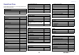
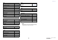

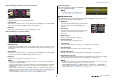
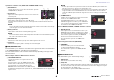
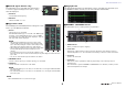
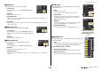
Table Of Contents
- How to Use This Reference Manual
- Contents
- Function Tree
- SELECTED CHANNEL section
- Channel Strip section
- Input and output patching
- Input channels
- Signal flow for input channels
- Specifying the channel name, icon, and channel color
- Making HA (Head Amp) settings
- Sending the signal from an input channel to the STEREO/MONO bus
- Added pan function (Monaural input channels only)
- Sending a signal from an input channel to a MIX/ MATRIX bus
- Channel name display indication
- Correcting delay between channels (Input Delay)
- Surround output for input channels
- Channel library operations
- OUTPUT channels
- Signal flow for output channels
- Specifying the channel name, icon, and channel color
- Sending signals from MIX channels to the STEREO/ MONO bus
- Sending signals from MIX channels and STEREO/ MONO channels to MATRIX buses
- Correcting delay between channels (Output Delay)
- Using the PORT TO PORT function
- Channel library operations
- EQ and Dynamics
- Channel Job
- Scene memory
- Monitor and Cue functions
- Talkback and Oscillator
- Meters
- Graphic EQ, Parametric EQ, effects, and Premium Rack
- I/O devices and external head amps
- MIDI
- Recorder
- Setup
- About the SETUP screen
- User settings
- Preferences
- USER DEFINED keys
- Functions that can be assigned to USER DEFINED keys
- USER DEFINED knobs
- Functions that can be assigned to USER DEFINED knobs
- Custom fader bank
- Console Lock
- Saving and loading setup data to and from a USB flash drive
- Remount function to USB flash drives
- Word clock and slot settings
- Using cascade connections
- Basic settings for MIX buses and MATRIX buses
- Switching the entire phantom power supply on/ off
- Specifying the brightness of the touch screen, LEDs, channel name displays, and lamps
- Setting the date and time of the internal clock
- Setting the network address
- Setting up the Dante audio network
- Using GPI (General Purpose Interface)
- Help function
- Other functions
- Initializing the unit to factory default settings
- Adjusting the detection point of the touch screen (Calibration function)
- Adjusting the faders (Calibration function)
- Fine-tuning the input and output gain (Calibration function)
- Adjusting the LED color (Calibration function)
- Adjusting the brightness of the channel name display
- Adjusting the contrast of the channel name display
- Initializing the Dante audio network settings
- Update procedure for NAME SUB CPU firmware
- Update function to Dante firmware
- Warning/Error Messages
- Index
- Data List
- Contents
- EQ Library List
- DYNAMICS Library List
- Dynamics Parameters
- Effect Type List
- Effects Parameters
- Premium Rack Processor Parameters
- Parameters that can be assigned to control changes
- NRPN parameter assignments
- Mixing parameter operation applicability
- MIDI Data Format
- Input/Output Specifications
- Electrical characteristics
- Mixer Basic Parameters
- Pin Assignment Chart
- MIDI Implementation Chart

SELECTED CHANNEL section
Reference Manual
8
If patched to a wireless mic (SELECTED CHANNEL VIEW screen)
1 RX.GAIN knob
Sets the gain for the receiver. Press the knob to open the
GAIN/PATCH 1ch window.
2 OL indicator
Lights if the audio signal level of the receiver reaches the
overload point.
3 RF (Radio Frequency) signal meter
Shows bars to indicate the level of the RF signal.
An active antenna indicator is shown on the right side. It indicates which antenna is
enabled.
NOTE
For more information about the relationship between the number of bars and the actual strength
of the RF signal, refer to the manual from Shure.
4 Battery indicator
Shows bars to indicate the remaining battery power.
NOTE
For more information about the relationship between the number of bars and maximum operation
time, refer to the manual from Shure.
5 MUTE indicator
Indicates the mute status (on/off) of the audio signal for the receiver.
6 Frequency
Indicates the frequency that is currently set for the RF signal.
PAN/BALANCE field
This field enables you to switch the on/off status of the signal sent from the selected channel
to the STEREO/MONO bus, and adjust the pan and balance.
The view and the function of the controllers in this field vary depending on the type of the
selected channel.
When an input channel or MIX channel is selected:
1 TO STEREO PAN knob
Sets the pan position of a signal routed to the
STEREO bus.
Press the knob to open the STEREO/MONO 8ch
window. If the ST IN channel is selected, you can
specify whether to view the PAN knob or the
BALANCE knob in this window. For a MIX channel,
the PAN knob will appear if the signal is mono, and the BALANCE knob will appear if the
signal is stereo.
NOTE
• For mono input channels, the pan level is nominal at center and +3dB when panned either left or
right. These levels do not change even if channel link is used.
• For ST IN channels, if the PAN knob is selected, the pan level is nominal when panned either left
or right and -3dB at center. If the BALANCE knob is selected the balance level is nominal at
center and +3dB when panned either left or right. These levels do not change even if channel link
is used.
2 ST/MONO button
Switches the on/off status of a signal sent from the
channel to the STEREO/MONO bus.
If an INPUT/MIX channel is set to LCR mode, the
LCR button appears in location
2. The LCR button
is an overall on/off switch for the signals sent from
the channel to the STEREO/MONO bus.
When a MATRIX, STEREO, or MONO channel is selected:
1 BALANCE knob
If the signal on the selected channel is stereo, the
BALANCE knob will appear, enabling you to adjust
the volume balance for the left and right channels.
If the channel signal is monaural, the BALANCE
knob is not shown and cannot be used.
Press the knob to open the TO STEREO 8ch
window.
When using Surround mode (MIX1-MIX6)
3 DOWN MIX
This field enables you to view the downmix
coefficient and L/R button settings.
Press this field to open the TO STEREO/MONO
window.
INPUT DELAY field
This field enables you to view the delay settings.
1 ON indicator
Indicates the on/off status of the delay.
2 Delay time
The delay value is displayed by milliseconds (ms) and also by currently-selected scale. If
the scale uses units of ms, the value in the bottom row will not be displayed. Only the
ms value appears in the middle row.
Press this field to open the INPUT DELAY 8ch window.
1
2
3
6
5
4
1
2
2
1
3
1
2