YAMAHA ® AUTHORIZED PRODUCT MANUAL
YAMAHA MULTITRACK CASSETTE RECORDER OPERATING MANUAL
Congratulations on your choice of the New Yamaha MT1X Multitrack Cassette Recorder. The MT1X is a compact multitrack recorder with a recording mixer, and is equipped with numerous versatile functions. Using conventional cassette tapes, the MT1X makes it easy for you to produce high quality multitrack recordings. Besides use as a multitrack recorder, the MT1X can also be used as a PA mixer for small performances, as well as for editing soundtracks for videos.
BEFORE OPERATION PLEASE NOTE THE FOLLOWING PRECAUTIONS: • ABOUT CASSETTE TAPE This unit is designed to be used only with Chromeposition tape, and will not work properly with Ferrichrome tape formulations. CrO tape (Bias: HIGH; EQ: 70µs) should be used. Also, the use of C-120 tapes is not recommended because they exhibit poorer performance, and can be the cause of equipment failure.
THE DIFFERENCE BETWEEN TRACKS AND CHANNELS The words “track” and “channel” are often confused. In order to properly operate this unit, it is necessary to understand the meanings of these terms. TRACK: The “band” on the tape itself where a certain signal is recorded. The tape inside a cassette has four different tracks, enabling the recording of four distinct signals. For conventional recordings, there are two tracks (stereo left and right) on each side of the tape.
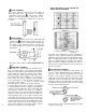
THE CONTROLS AND THEIR FUNCTIONS This section explains the names and functions of all the knobs, sliders, and switches for the mixer, recorder, meter/ monitor, and connector sections. Familiarize yourself with them in order to take full advantage of the MT1X’s versatile functions. MIXER SECTION INPUT SELECTOR SWITCHES These three-position switches are provided for each channel. Position them according to the operation to be performed.
GAIN CONTROLS The controls adjust the input level of the channel to match the output level of a microphone or instrument connected to input jack Control from -10dB to -50db is possible. Adjust the output level of the microphone or instrument as outlined in its instruction booklet. SOUND CHARACTERISTICS OF THE EQUALIZER AND VARIOUS MUSICAL INSTRUMENTS INPUT FADERS These controls adjust the volume of the signal input, and send it to the equalizer.
AUX CONTROLS The MT1X is equipped with an AUX SEND jack and two (left and right) AUX RETURN jacks When special acoustic effects are desired on a certain channel, reverbs or delay effects can be connected between these jacks to provide only the desired effect to the desired channel. Amplified monitor speakers can also be connected to the AUX SEND jack. Each AUX control adjusts the sources connected to the AUX SEND jack in the following manner.
AUX MASTER SEND CONTROL This control adjusts the level of the effect-mixed signals from each channel (adjusted by each AUX control as well as the AUX signal for monitoring use. The final output is through the AUX SEND jack AUX RETURN CONTROL This control adjusts the input level of effects or submixers connected to the AUX RTN jack . The level of effect in relation to the sound can be set with this control.
RECORD SELECT SWITCHES These switches are used to choose the signal to be recorded. The upper left switch is for track 1, the upper right switch is for track 2, the lower left switch is for track 3, and the lower right switch is for track 4. When the track is not to be recording, set the corresponding switch to the OFF position. Switch ON only those switches corresponding to the tracks which are to record.
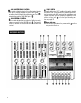
METER AND MONITOR SECTION METER SELECT SWITCH This switch is used to select the signal for level indication by the Peak Level Meters STEREO Position: The level of the signal output through the ST OUT jacks is indicated. The meter on the far left shows the level of the Left channel of the stereo signal, while the second meter from the left shows the level of the Right channel. Setting to this position during pingponging or mixdown operations enables easy reading of the recording level.
PHONES SELECT SWITCH You can plug a set of headphones into the PHONES jack on the front panel to monitor the sound. This switch is used to select the signal to be monitored. Control the volume level with the PHONES volume control STEREO Position: Put the switch in this position to monitor the signal output through the ST OUT jacks The Left and Right channels of the stereo signal will be heard through the headphones.
MONITOR LEVEL CONTROLS When setting the PHONES SELECT Switch to the MONITOR position, these level controls are used for each track to achieve a level balance for easy monitoring. Use these controls freely and independently to maintain a desired level balance during overdubbing operations, when the addition of a new signal changes the volume.
POWER SWITCH This switch turns on the MT1X. When switching the unit on or off, make sure that the Input Faders and the AUX RTN Control are at the “0” position. DC IN JACK Connect the supplied AC adaptor to this terminal. To prevent damage, use only the AC adaptor supplied with this unit. SYNC IN/SYNC OUT JACKS These jacks are used during synchronized operation with MIDI-equipped instruments.
CONNECTION EXAMPLES BASIC CONNECTION LAYOUT FOR MULTITRACK RECORDING 13
ABOUT CASSETTE TAPES This unit is designed to be used only with Chromeposition tape, and will not work properly with Ferrichrome tape formulations. CrO tape (Bias: HIGH; EQ: 70µs) should be used. Also, the use of C-120 tapes is not recommended because they exhibit poorer performance, and can be the cause of equipment failure.
ATTACHING THE STRAP The MT1X can be easily carried with the supplied carrying strap. Here’s how to attach it. Push on the slit to open the stopper, and hang it on the peg. Slide the strap to the desired position and lock the stopper in place. WHEN USING THE BATTERY PACK With the optional PA11 Battery Pack, the MT1X can be operated by batteries in places where there is no AC outlet available. Here’s how to set it up. • PUTTING IN THE BATTERIES Slide off the battery cover on the bottom of the battery pack.
MULTITRACK RECORDING TECHNIQUES Before you try to attempt a multitrack recording on your own, it’s absolutely essential that you understand the function of all the controls, switches, and connectors in each section. In addition, you should spend an adequate amount of time to familiarize yourself with the block diagram on page 35.
MULTITRACK RECORDING PLAN YOUR RECORDING A clear plan is essential before you begin multitrack recording. If you begin cold, without regard to all the steps involved, you may “record yourself into a corner” by running out of available empty tracks, missing the chance to add effects at the proper points, losing control over the final stereo positioning of the instruments, and creating the need for more ping-pong and mixdown recording operations than really necessary.
— Drum Recording Procedure — 1. Connections Plug the AC adaptor into an AC outlet, and insert the small round plug into the DC IN jack. Plug the four microphones into input jacks 1-4. Plug a pair of monitor headphones (rated 8-40 ohms) into the PHONES jack. When using an effect, connect it between the AUX SEND jack (input) and either of the AUX RTN jacks (output). 2. Getting ready Lift open the cassette door and insert a chrome position (CrO2) tape. Bias: HIGH, Eq: 70us.
4. Setting the monitor and meter sections Set the PHONES SELECT switch to the “STEREO” position. Set the PHONES volume to around “7”. Make sure the METER SELECT switch is in the “4 TRK” position. 5. Adjusting the input level Set all of the input switches to the MIC/LINE position. Set the MASTER fader to “7”. Set the PAN controls for all channels between the center and the extreme “L" position, as shown. Push the input fader for channel 1 up to “7”.
*Explanation diagram for steps 6. Adjusting level balance and equalization characteristics Adjust channel faders 1 ~4 to achieve the desired recording level balance. Adjust the equalizers for 1~4 to obtain the desired sound character for each individual channel. (If you’re thinking of ping-ponging these tracks afterwards, it’s a good idea to add a little boost on the HIGH EQ because high frequencies can be slightly diminished during the ping-pong re-recording process).
Make sure this switch is in the “4 TRK” position. Set this so you can monitor track 1. Press to check the recording on track 1, then rewind. *Explanation diagram of steps 8. Post recording check Return all switches and controls to their normal positions. Set the PHONES SELECT switch to the “MONITOR” position, turn MONITOR LEVEL control 1 to “7’: then turn the PHONES volume control to about “7”. Make sure the METER SELECT switch is set to “4 TRK".
RECORDING THE BASS GUITAR BY OVERDUBBING Overdubbing is the playing back previously recorded tracks while recording a new instrument on a different track. With this technique, it’s possible for one musician to play many different instrumental parts on a single recording. If you’re multitalented, multitrack overdubbing can clone you into your own group. Now, we’re going to record a bass guitar on track 2 to synch with, or match, with the drum part already recorded on track 1.
— Bass guitar recording procedure — 1. Connections Connect everything through input jack 2 as follows. If the GC2020 is being used, connect it between the amplifier and input jack 2. When not using a bass amp, the use of a direct box is recommended. Connect the monitor headphones. Until the mixdown process, only use headphones and avoid using monitor speakers. (This also goes for the rest of the steps.) 23 2. Setting the recorder Make sure the tape has been rewound to the “999” point on the counter.
Equalizer controls Press the PAUSE button and adjust the monitor levels Set to the MIC/LINE position Set by the reading on the level meter Push up to about “7” Set after setting equalization 4. Adjusting the Input level Set the input selector switch to the MIC/LINE position. Push input fader 2 up to about “7”.
RECORDING THE RHYTHM GUITAR Record the rhythm guitar on track 3 to synch with the drums on track 1 and the bass guitar on track 2. Recording preparations and operations are the same as when recording the bass guitar. If effects are being used, connect them just before the input jack. Track 1 Track 2 Track 3 Track 4 PING-PONG < PING-PONG RECORDING > After the rhythm section has been recorded on tracks 1 — 3, only track 4 remains as an empty, spare track.
— Ping-pong Recording Procedure — Equalizer controls Make sure it’s set to “4 TRK” Turn to about “7” Set the “R” position 1. Setting the recorder Set the RECORD SELECT switch to the “R” position to mix the sound of the drums, bass guitar, and rhythm guitar through the stereo buss. The REC indicator will flash. Press the PAUSE switch, then the REC switch to put the recorder into the REC PAUSE mode. The REC indicator will light. 2.
RECORDING THE KEYBOARDS BY OVERDUBBING Now that the recording of the drums on track 1 has been ping-ponged onto track 4, this track is free for recording the keyboards. RECORDING THE LEAD GUITAR BY OVERDUBBING Just like with the keyboards, the lead guitar can be recorded on track 2. Both the keyboards and the lead guitar can be positioned Left and Right with the PAN controls during mixdown.
— Signal Path during Punch-in/Punch-out Operation — Before and after the punch-in, the sound from tracks 1-4 plus the new sounds to be recorded can be monitored. However, during the punch-in, only the sound from tracks 1, 2, and 4 plus the new sound being recorded can be monitored.
— Punch-in/Punch-out Procedure — 1. Connections Connect the vocal microphone through input jack 3. If the FS-1 Foot Switch is being used, connect it to the PUNCH IN/OUT jack. 2. Setting the recorder If the FS-1 Foot Switch is connected, set RECORD SELECT switch 3 to the “3” position. The REC indicator will flash. After pressing the PAUSE switch, press the REC switch. (If the FS-1 is being used, the unit is put into the REC PAUSE mode, and the REC indicator lights.
*Explanation diagram for steps 4. Setting input levels Set input select switch 3 to “MIC/LlNE”. Set both input fader 3 and the MASTER fader to “7”. Slide gain control 3 in the “MIC” direction, stopping when the “+3” LED indicator on the. level meter third from the left flashes occasionally on music peaks. (Setting the same as when the vocals were initially recorded is recommended.) 5.
MIXDOWN (TRACKDOWN) It’s now time for the mixdown. Often called “trackdown” or “remix”, mixdown is when all the four recorded tracks are mixed to achieve a certain sound’ balance in level, effects, and stereo positioning, and then recorded onto one side of a cassette tape in mono or stereo. This tape is the final “master”.
— Mixdown Procedure — *Explanation diagram for steps 1. Connections Connect a stereo tape deck to the ST OUT jack, and insert a blank tape to record the final mix in stereo. Connect the REV7 Digital Reverberator through the AUX SEND jack and AUX RETURN jacks. 2. Setting the meter and monitor sections Set the PHONES SELECT switch to “STEREO” in order to monitor the mixed down sound. Turn the PHONES volume to about “7”.
SYNC-RECORDING For synchronized operation with MIDI instruments, the optional YMC10 MIDI converter enables synchrooperation of the CMX1 and MIDI instruments such as the RX11, RX15, and RX21 digital rhythm programmers and the QX1 and QX7 digital sequence recorders. In this section, we will explain synchro-recording using synchro-operation techniques.
EDITING VIDEO SOUNDTRACKS Most people will agree that the sound recorded by the video camera’s microphone just isn’t enough for a good music video. Using the MT1X to edit down a good soundtrack for your video is a great idea, and will result in a video that sounds surprisingly professional. You’ll find this capability useful to produce a promotional video for your group.
BLOCK DIAGRAM NOTE: When the REC button is engaged, the panel switches can be used to individually order recording on only those channels with RECORD SELECT not switched “OFF”.
SPECIFICATIONS Model Description Mechanical Descriptions Tape Heads Tape speed Pitch control Wow & flutter Fast forward/rewind time Motor Inputs & Outputs INPUT 1—4 AUX RTN L/R ST OUT L/R AUX SEND TAPE OUT 1—4 PHONES Equalizer Characteristics : multitrack cassette recorder : standard cassette; CrO2 tape only (EQ: 70µs) : hard permalloy 4-channel rec/play head ferrite 4-channel erase head : 4.75 cm/sec : +/-10% : 0.
INTRODUCTION TO THE ACCESSORIES 37
SERVICE The MTlX is supported by Yamaha’s worldwide network of factory trained and qualified dealer service personnel. In the event of a problem, contact your nearest Yamaha dealer.
SINCE 1887 NIPPON GAKKI CO., LTD.
YAMAHA Recyclable ® MT1X OM Yamaha Corporation of America 6600 Orangethorpe Avenue, P.O.