
User Manual


CL Editor Owner’s Manual
40
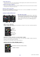
3 ON
This button switches on/off for the compressor or the expander.
4 Response curve
Indicates the response for the compressor/expander of the currently selected channel.
5 GR meter (Gain Reduction meter)
This meter indicates the amount of gain reduction produced by the compressor/expander.
6 THRESH (Threshold level)
Specifies the threshold level at which the compressor/expander will operate. If the compressor is selected, the input sig-
nal will start being compressed when the key-in signal exceeds this level; compression will be removed when the signal
falls below this level. If the expander is selected, the input signal will start being compressed when the key-in signal falls
below this level; compression will be removed when the signal exceeds this level.
7 RATIO
If the compressor is selected, specifies the ratio at which the input signal will be compressed when the key-in signal
exceeds the threshold. If the expander is selected, specifies the ratio at which the input signal will be compressed when
the key-in signal falls below the threshold.
8 KNEE
Specifies the sharpness at which the output level will change. You can select from HARD or 1–5.
9 ATTACK
If the compressor is selected, specifies the time (the attack time) from when the key-in signal exceeds the threshold
level until the signal starts being compressed. If the expander is selected, specifies the time (the attack time) from when
the key-in signal falls below the threshold level until the signal starts being compressed.
0 GAIN
Adjusts the gain of the signal after it has passed through the compressor/expander.
A RELEASE
If the compressor is selected, specifies the time (the release time) from when the key-in signal falls below the threshold
level until compression is removed. If the expander is selected, specifies the time (the release time) from when the key-
in signal exceeds the threshold level until compression is removed.
B KEY IN SOURCE
Click this to select the key-in signal that you want to use.
The choices are the same as for GATE.
C CUE (DYNAMICS 1 only)
This button cue-monitors the currently selected key-in signal. This is not shown in the Additional View.
In the ONLINE state, if MATRIX bus channels 7 and 8 can be used as a second cue, the indication is fixed at “CUE A.”
This is not shown if the Channel Select/Sends On Fader checkbox in the System Setup dialog box is not
checked.
D KEY IN FILTER (DYNAMICS 1 only)
Select the type of filter applied to the selected key-in signal; HPF (high pass filter), BPF (band pass filter), or LPF (low
pass filter.) The ON/OFF button switches the filter on/off.
If BPF is selected, the two knobs adjust the bandpass frequency and the Q. If HPF and LPF are selected, the knob
adjusts the cutoff frequency.
NOTE