
User Manual
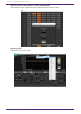
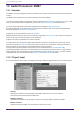
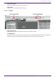
Table Of Contents
- ProVisionaire Design
- Contents
- 1. Introduction
- 2. Screen structure
- 3. The basics of using ProVisionaire Design
- 4. Menu bars and toolbar
- 5. Shortcut keys
- 6. List of alerts
- 7. "Project" sheet
- 8. "Tuning" sheet
- 9. Online and synchronization
- 10. Dialog boxes
- 10.1. Startup dialog box
- 10.2. "Go Online- From Devices" dialog box
- 10.3. "Protect File" dialog box
- 10.4. "Project Information" dialog box
- 10.5. "Print" dialog box
- 10.6. "File Storage" dialog box
- 10.7. "Network Setup" dialog box
- 10.8. "IP Settings" dialog box
- 10.9. "IP Address" dialog box
- 10.10. "Auto-Assign IP Addresses" dialog box
- 10.11. "Match Devices by IP Address" dialog box
- 10.12. "Device Information" dialog box
- 10.13. "Update Firmware" dialog box
- 10.14. "Initialize" dialog box
- 10.15. "Word Clock" dialog box
- 10.16. "Protect Devices" dialog box
- 10.17. "Clock" dialog box
- 10.18. "Daylight Saving Time" dialog box
- 10.19. "GPI Calibration" dialog box
- 10.20. "Get Log from Devices" dialog box
- 10.21. "RM Series Settings" > "Sign up" dialog box
- 10.22. "RM Series Settings" > "Login" dialog box
- 10.23. "RM Series Settings" > "Password Settings" dialog box
- 10.24. "RM Series Settings" > "Enable SCP remote control access" dialog box
- 10.25. "Linked Presets Manager" dialog box
- 10.26. "Store Linked Preset" dialog box
- 10.27. Port Label Dialog
- 11. Context menus
- 12. Common operations for device sheets
- 13. Audio Processors: DME7
- 13.1. Overview
- 13.2. "Project" sheet
- 13.3. Device sheet screen configuration
- 13.4. Basic use of ProVisonaire Designer
- 13.5. Tool buttons
- 13.6. "Components" area
- 13.7. Design sheet
- 13.8. Design sheet: Audio layer
- 13.9. Design sheet: Control layer
- 13.10. Components other than audio or control components
- 13.11. “Parameter Sets” area
- 13.12. “Properties” area
- 13.13. "Parameters" area
- 13.14. Context Menu
- 13.15. Dialog box
- 13.16. Message List
- 14. Audio Processor MRX7-D
- 14.1. Overview
- 14.2. Project Sheet
- 14.3. Device Sheet Screen Configuration
- 14.4. Basic Use
- 14.5. Tool Buttons
- 14.6. Components Area
- 14.7. Design Sheet
- 14.8. Non-Audio Components
- 14.9. Parameter Sets Area
- 14.10. Presets Area
- 14.11. Parameter Link Group Area
- 14.12. Gang Edit Group Area
- 14.13. Properties Area
- 14.14. Parameters Area
- 14.15. Context Menu
- 14.16. Dialog
- 14.17. Component Editor
- 14.18. Alert List
- 14.19. Flow of Paging Configuration
- 15. Audio Processors: MTX5-D/MTX3
- 15.1. Overview
- 15.2. "Project" sheet
- 15.3. Device sheet screen configuration
- 15.4. Tool buttons
- 15.5. "Presets" area
- 15.6. Context menus
- 15.7. Dialog box
- 15.8. Alert list
- 15.9. Component editors
- 15.9.1. "Analog In" component editor
- 15.9.2. “MY4-AEC” component editor
- 15.9.3. "Input CH" component editor
- 15.9.4. "Insert" component editor
- 15.9.5. "Zone" component editor
- 15.9.6. "Output CH" component editor
- 15.9.7. "Pilot Tone" component editor
- 15.9.8. "Analog Out" component editor
- 15.9.9. "Slot Out" component editor
- 15.9.10. "DCA Groups"/"Mute Groups" component editor
- 15.10. Workflow for paging settings
- 16. MTX I/O Expanders: EXi8 / Exo8
- 17. Power Amplifiers: PC-series
- 18. Power Amplifiers: XMV-series
- 19. I/O Interface: Rio3224-D2 / Rio1608-D2
- 20. I/O Interface: Tio1608-D / Tio1608-D2
- 21. I/O Interface: RSio64-D
- 22. Powered Speakers: VXL1-16P
- 23. Microphones: PGM1
- 24. Microphones: RM-CG
- 25. Microphones: RM-TT
- 26. External Device: Speakers
- 27. DCP
- 28. Wall-mount Controller: MCP1
- 29. YDIF
- 30. Settings for controlling devices across subnets
-

13. Audio Processors: DME7
13.1. Overview
The DME7 is a freely configurable processor that allows you to place components as desired to freely design a
system.
The DME7 can be operated from an external controller such as DCP/MCP1.
In the device sheet of DME7, your workflow consists of freely placing Components and then Compile the result.
Then, in communication with the DME7 unit, you’ll use the Component editor to edit the parameters.
The Trace Signal Path function allows the signal path to be displayed (signal path display).
By using the Duplicate Port Label function, you the name of the starting port can be successively duplicated
along the signal path (input port name duplication).
Parameters are stored/recalled in the form of Snapshot.
Multiple parameters that you want to store/recall can be grouped (Parameter Sets), and 100 sets of parameter
values can be stored for each parameter set as snapshots.
Snapshots can also be recalled from a remote controller.
The initial values of a component, together with data that specifies the wiring between components, can be
saved on a computer as a User style. By saving a user style, don’t have to change the settings each time you
place a component. User styles can also be transferred to another computer.
Components and the wires between components can be encapsulated as a User Defined Block. By
encapsulating multiple components as a single block, you can make the sheet look cleaner, or copy blocks to
easily create the same functionality for other channels. By specifying “View Only” mode or “Protect” mode for
individual blocks, you can protect blocks when “Protect User Defined Block” is executed.
13.2. "Project" sheet
You can place devices in this sheet. The following “Settings” dialog box appears when you try to place a device.
•
Capacity
Specifies the signal processing capacity of the DME7. Select from 64, 128, 192, and 256.
This capacity must match that of the DME7 unit.
•
Sampling Frequency
Specifies the sampling rate for the device. Select from 44.1kHz, 48kHz, 88.2kHz, and 96kHz.
•
Number of Devices
Selects the number of DME7 units to be placed in the “Device” sheet.
13. Audio Processors: DME7
118 | ProVisionaire Design V1.2 User Guide